Supply air unit, VEKA
Supply air unit, VEKA
Supply air unit, VEKA

Create successful ePaper yourself
Turn your PDF publications into a flip-book with our unique Google optimized e-Paper software.
<strong>Supply</strong> <strong>air</strong> <strong>unit</strong>, <strong>VEKA</strong><br />
Technical data 2008
<strong>Supply</strong> <strong>air</strong> <strong>unit</strong>, <strong>VEKA</strong><br />
Technical data<br />
Contents<br />
Description of the <strong>unit</strong>............................................................3<br />
Technical data, quick selection..............................................4<br />
Components..............................................................................5<br />
Technical data, size 20.............................................................6<br />
Technical data, size 30.............................................................8<br />
Technical data, dimensioning..............................................10<br />
Control and regulation equipment – STVE for <strong>VEKA</strong>.....11<br />
Accessories..............................................................................16<br />
Product code...........................................................................18<br />
Fläkt Woods 8513 GB 2008.07 <br />
Subject to alteration.
<strong>Supply</strong> <strong>air</strong> <strong>unit</strong>, <strong>VEKA</strong><br />
Technical data<br />
Description of the <strong>unit</strong><br />
<strong>VEKA</strong> is an <strong>air</strong> treatment <strong>unit</strong> with a low overall<br />
height and offers the right solution when the installation<br />
space is limited. <strong>VEKA</strong> is available in two sizes.<br />
<strong>VEKA</strong> can be supplied with the following combinations<br />
of components installed inside the casing:<br />
• Filter + fan<br />
• Filter + <strong>air</strong> heater/cooler + fan<br />
• Filter + <strong>air</strong> heater + <strong>air</strong> cooler + fan<br />
A sound attenuator and an electrical heater are installed<br />
in the duct .<br />
Execution<br />
The casing is made of galvanized pre-painted sheet,<br />
white, with 25 mm mineral wool insulation sandwiched<br />
in between.<br />
The outer casing of <strong>VEKA</strong> is completely white.<br />
Thanks to its decorative appearance, <strong>VEKA</strong> can also<br />
be positioned in a visible place. The handles are recessed,<br />
which gives the <strong>unit</strong> a completely smooth surface<br />
without any projecting parts that can get in the way.<br />
<strong>VEKA</strong> has large service hatches equipped with locking<br />
handles that can be opened with tools.<br />
The principal components in <strong>VEKA</strong> are fitted in<br />
the casing at the factory, which reduces the on-site<br />
installation work and gives a compact design.<br />
<strong>VEKA</strong> is hygienic and easy to clean thanks to its<br />
smooth inside.<br />
External dimensions<br />
<strong>VEKA</strong> is a compact <strong>unit</strong> with small external dimensions.<br />
The height is only 355 mm, and the combination<br />
of a filter + <strong>air</strong> heater + fan is only 1000 mm<br />
long. Thanks to the small dimensions, <strong>VEKA</strong> is easily<br />
positioned in practically any desired location, e.g.<br />
above a false ceiling.<br />
Alternative installation<br />
<strong>VEKA</strong> is normally installed by suspending it from a<br />
ceiling. The <strong>unit</strong> is arranged so that the service hatches<br />
open downwards. Therefore no service space is<br />
required next to the <strong>unit</strong>. Suspension eyes are supplied<br />
for use in installation. <strong>VEKA</strong> can also be installed<br />
on a wall with a horizontal or vertical <strong>air</strong> direction.<br />
Applications<br />
<strong>VEKA</strong> is an appropriate supply <strong>air</strong> <strong>unit</strong> for the ventilation<br />
of business premises, cafés, fast-food stands,<br />
kiosks, service stations or similar premises which lack<br />
the space for an integral ventilation <strong>unit</strong>.<br />
<strong>VEKA</strong> is particularly suitable as a circulation <strong>unit</strong>, for<br />
heating large porches and as a curtain <strong>unit</strong> in door<br />
openings.<br />
Electrical, control and regulation equipment<br />
<strong>VEKA</strong> has integrated control equipment for 1-phase<br />
connection, which makes <strong>VEKA</strong> a complete and functional<br />
supply <strong>air</strong> <strong>unit</strong> with the additional ability to<br />
control an exhaust <strong>air</strong> fan. <strong>VEKA</strong> can also be ordered<br />
with more advanced control equipment that has the<br />
same functions as the integrated control and regulation<br />
equipment, but also has communication facilities<br />
and can be connected to a 3-phase supply. The <strong>VEKA</strong><br />
<strong>unit</strong> can also be ordered without a control equipment.<br />
Fläkt Woods 8513 GB 2008.07 <br />
Subject to alteration.
<strong>Supply</strong> <strong>air</strong> <strong>unit</strong>, <strong>VEKA</strong><br />
Technical data<br />
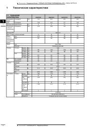
Technical data, quick selection<br />
Flow range<br />
<strong>VEKA</strong> size 30, Heating battery, electric<br />
<strong>VEKA</strong> size 30,<br />
Cooling battery, liquid<br />
<strong>VEKA</strong> size 30, Heating battery, liquid<br />
<strong>VEKA</strong> size 20,<br />
Heating battery, electric<br />
<strong>VEKA</strong> size 20,<br />
Cooling battery, liquid<br />
<strong>VEKA</strong> size 20, Heating battery, liquid<br />
0 0,2 0,4 0,6 0,8 1,0 1,2 m 3 /s<br />
Dimensions and weight<br />
Size Variant (bb) Width Height Length Weight Duct connection<br />
20 Fan + short filter (bb=12) 750 355 500 50 600x250<br />
Fan + long filter (bb=13) 750 355 750 55 600x250<br />
Fan, heating or cooling battery + long filter (bb=14) 750 355 1000 70 600x250<br />
Fan, heating battery, cooling battery + long filter (bb=15) 750 355 1250 80 600x250<br />
30 Fan + short filter (bb=12) 1050 355 500 65 900x250<br />
Fan + long filter (bb=13) 1050 355 750 70 900x250<br />
Fan, heating or cooling battery + long filter (bb=14) 1050 355 1000 85 900x250<br />
Fan, heating battery, cooling battery + long filter (bb=15) 1050 355 1250 100 900x250<br />
Dimensional drawing size 20 Dimensional drawing size 30<br />
Height<br />
Height<br />
Duct connection<br />
Duct connection<br />
Width<br />
Length<br />
Width<br />
Length<br />
Fläkt Woods 8513 GB 2008.07 <br />
Subject to alteration.
<strong>Supply</strong> <strong>air</strong> <strong>unit</strong>, <strong>VEKA</strong><br />
Technical data<br />
Components<br />
Fan<br />
The fan is a direct driven radial fan with forwardcurved<br />
blades. Its <strong>air</strong> flow and pressure increase are<br />
regulated by controlling the fan speed. It is insulated<br />
from the <strong>unit</strong> casing with a vibration damper and is<br />
equipped with a sensor for <strong>air</strong> flow measurement.<br />
The measurement sockets are connected to nipples on<br />
the outside of the casing.<br />
Accompanying the <strong>unit</strong> are <strong>air</strong> distributors that are<br />
easily installed on the fan outlets for subsequent functions<br />
such as a sound attenuator and electrical heater.<br />
Air flow indicator VEKZ-27, which can be mounted<br />
on the <strong>unit</strong>, is available as an accessory. With the help<br />
of the <strong>air</strong> flow indicator, the <strong>air</strong> flow of the system<br />
can be readily checked in conjunction with commissioning.<br />
Transition piece, VEKZ-53<br />
Used for duct connection and installed, for<br />
example, on a duct heater. It has a PG-connection<br />
at one end and a flange at the other.<br />
Air heater and <strong>air</strong> cooler for water<br />
Finned heat exchangers with Cu tubes and Al<br />
fins are used as an <strong>air</strong> heater and <strong>air</strong> cooler.<br />
The <strong>air</strong> heaters are available with 2-tube or 3-<br />
tube rows. The frost protection sensors of the<br />
<strong>air</strong> heaters can be installed in a finned tube.<br />
The <strong>air</strong> coolers are available with 4-tube rows<br />
and are provided with a stainless steel condensation<br />
water trough with an outlet on the<br />
inspection side.<br />
A <strong>unit</strong> with an <strong>air</strong> cooler may only be mounted<br />
horizontally and with the service hatches<br />
facing downwards.<br />
Cut-off damper for duct installation, VEVA<br />
The rectangular cut-off damper for duct installation<br />
directly to the inlet of the <strong>unit</strong> is made<br />
of galvanized steel sheet and can be provided<br />
with an attached on/off actuator with springassisted<br />
return. The damper has a connection<br />
frame for a guide and is mounted directly on<br />
the <strong>unit</strong>. The damper blades are connected via<br />
external toothed wheels made of PP plastic.<br />
Electrical duct heater, VEEK<br />
The electrical heater is installed in a<br />
duct and has its own control cabinet<br />
for temperature regulation.<br />
The electrical heater is equipped<br />
with automatic and manual overheating<br />
protection.<br />
Flexible sleeve, VEKZ-51<br />
Flexible sleeve of fibreglass<br />
fabric for flexible connection<br />
of ducts.<br />
Duct sound attenuator, VELD<br />
The duct sound attenuator is of the baffle<br />
type with a surface coating of Cleantec to<br />
prevent fibres from being carried along.<br />
The sound attenuator can be used on both<br />
the suction and the pressure side.<br />
Filter<br />
<strong>VEKA</strong> is provided with a<br />
bag filter that is available<br />
in two lengths. Good<br />
sealing around the filter is<br />
achieved with a clamping<br />
device, which presses the<br />
filter frame against a soft<br />
rubber gasket.<br />
Counter-flange, VEKZ-52<br />
Used to mount a duct<br />
directly on the <strong>unit</strong>’s<br />
inlet.<br />
Fläkt Woods 8513 GB 2008.07 <br />
Subject to alteration.
<strong>Supply</strong> <strong>air</strong> <strong>unit</strong>, <strong>VEKA</strong><br />
Technical data<br />
Technical data, size 20<br />
Dimensions and weight<br />
Fan and short filter<br />
(bb=12)<br />
bb Weight Filter type Filter length<br />
<strong>unit</strong> (mm) (mm)<br />
12 50 287 x 592 120<br />
13 55 287 x 592 360<br />
14 70 287 x 592 360<br />
15 80 287 x 592 360<br />
Electrical data<br />
500<br />
Size 20 Recommended <strong>Supply</strong><br />
fuses<br />
Without control equipment 10 A 230/400 V<br />
Integrated control equipment 16 A 1 x 230 V<br />
Separate control cabinet 16 A* 3 x 400 V<br />
Frequency changer 10 A 3 x 400 V<br />
* Without exhaust <strong>air</strong> fan 10 A<br />
Fan and long filter<br />
(bb=13)<br />
Fan, heating battery, cooling battery<br />
and long filter (bb=15)<br />
44 44<br />
508*<br />
508*<br />
INV DN 8<br />
DN 25<br />
80<br />
80<br />
98<br />
750<br />
Drain Ø15 L= 0<br />
1250<br />
Fan, heating or cooling battery<br />
and long filter (bb=14)<br />
44<br />
456* 500*<br />
* Viewed in direction of <strong>air</strong> flow<br />
Connection dimensions, inlet and outlet<br />
INV DN 8<br />
80<br />
M8<br />
250<br />
274<br />
355<br />
DN 25<br />
80<br />
98<br />
600<br />
620<br />
750<br />
1000<br />
* Viewed in direction of <strong>air</strong> flow<br />
Fläkt Woods 8513 GB 2008.07 <br />
Subject to alteration.
<strong>Supply</strong> <strong>air</strong> <strong>unit</strong>, <strong>VEKA</strong><br />
Technical data<br />
Technical data, size 20<br />
Fan graph<br />
The graph is intended to provide an overview.<br />
Exact data can be found in our <strong>unit</strong> selection<br />
program, ACON. The graph shows the available<br />
external pressure drop for the duct system.<br />
Pressure drop through the filter and any coils must<br />
be added to the external pressure drop. The indicated<br />
weighted sound power levels in dB(A) are<br />
applicable in a duct on the outlet side of the fan.<br />
Size 20 with 3-phase motor<br />
49<br />
Hz<br />
55<br />
48<br />
Hz<br />
55<br />
39<br />
38<br />
29<br />
29<br />
20<br />
19<br />
C= 4 motor: 0.75 kW, 2-pole, 230/400 V, 3-phase,<br />
50 Hz 3.65 / 2.10 A, recommended fuse 10 A<br />
C= 5 motor: 1.5 kW, 2-pole, 230/400 V, 3-phase,<br />
50 Hz 6.25 / 3.6 A, recommended fuse 10 A<br />
The speed of the fans can be controlled with a frequency changer.<br />
Δpt = total pressure increase of the fan, excluding outlet loss<br />
Fläkt Woods 8513 GB 2008.07 <br />
Subject to alteration.
<strong>Supply</strong> <strong>air</strong> <strong>unit</strong>, <strong>VEKA</strong><br />
Technical data<br />
Technical data, size 30<br />
Dimensions and weight<br />
Fan and short filter<br />
(bb=12)<br />
bb Weight Filter type Filter length<br />
<strong>unit</strong> (mm) (mm)<br />
12 65 287 x 892 120<br />
13 70 287 x 892 360<br />
14 85 287 x 892 360<br />
15 100 287 x 892 360<br />
Electrical data<br />
Size 30 Recommended <strong>Supply</strong><br />
fuses<br />
500<br />
Without control equipment 10 A 230/400 V<br />
Integrated control equipment 16 A 1 x 230 V<br />
Separate control cabinet 16 A* 3 x 400 V<br />
Frequency changer 10 A 3 x 400 V<br />
* Without exhaust <strong>air</strong> fan 10 A<br />
Fan and long filter<br />
(bb=13)<br />
Fan, heating battery, cooling battery<br />
and long filter (bb=15)<br />
44 44<br />
508* 508*<br />
INV DN 8<br />
DN 25<br />
80<br />
80<br />
98<br />
750<br />
Drain Ø15 L= 0<br />
1250<br />
Fan, heating or cooling battery<br />
and long filter (bb=14)<br />
44<br />
456* 500*<br />
* Viewed in direction of <strong>air</strong> flow<br />
Connection dimensions, inlet and outlet<br />
INV DN 8<br />
DN 25<br />
80<br />
80<br />
M8<br />
250<br />
274<br />
355<br />
98<br />
900<br />
920<br />
1050<br />
1000<br />
* Viewed in direction of <strong>air</strong> flow<br />
Fläkt Woods 8513 GB 2008.07 <br />
Subject to alteration.
<strong>Supply</strong> <strong>air</strong> <strong>unit</strong>, <strong>VEKA</strong><br />
Technical data<br />
Technical data, 30<br />
Fan graph<br />
The graph is intended to provide an overview.<br />
Exact data can be found in our <strong>unit</strong> selection<br />
program, ACON. The graph shows the available<br />
external pressure drop for the duct system.<br />
35<br />
Hz<br />
50<br />
Pressure drop through the filter and any coils must<br />
be added to the 44 external pressure drop. The indicated<br />
weighted sound power levels in dB(A) are<br />
applicable in a duct on the outlet side of the fan.<br />
26<br />
Size 30 with 3-phase motor<br />
18<br />
44<br />
Hz<br />
50<br />
35<br />
26<br />
18<br />
C=6 motor: 1.5 kW, 2-pole, 230/400 V, 3-phase, 50 Hz<br />
5.8 / 3.7 A, recommended fuse 10 A<br />
The speed of the fans can be controlled with a frequency<br />
changer.<br />
Δpt = total pressure increase of the fan, excluding outlet loss<br />
Fläkt Woods 8513 GB 2008.07 <br />
Subject to alteration.
<strong>Supply</strong> <strong>air</strong> <strong>unit</strong>, <strong>VEKA</strong><br />
Technical data<br />
Technical data, dimensioning<br />
Dimensioning of <strong>unit</strong> via the web<br />
Air handling configuration – ACON is the name<br />
of the new generation web based product selection<br />
program.<br />
<strong>VEKA</strong> is dimensioned rapidly and easily with<br />
ACON. The program gives a <strong>unit</strong> specification and<br />
all facts such as dimensions, efficiencies, sound<br />
levels, etc. The program also provides product-specific<br />
documentation relating to installation, mounting<br />
and care.<br />
In order to access the program, you will need a<br />
user-ID and a password. You can obtain these by<br />
contacting our nearest sales office. Visit our web<br />
site, www.flaktwoods.se to locate your nearest sales<br />
office.<br />
• Always the latest version of the software<br />
• No installation required<br />
• Always available on the Internet<br />
• Fan curve with operating points, etc.<br />
• Unit drawing can be exported to CAD<br />
• Current delivery dates from the ordering<br />
function.<br />
Fläkt Woods 8513 GB 2008.07 10<br />
Subject to alteration.
<strong>Supply</strong> <strong>air</strong> <strong>unit</strong>, <strong>VEKA</strong><br />
Technical data<br />
Control and regulation equipment for <strong>VEKA</strong><br />
There are three alternatives for control and regulation equipment for <strong>VEKA</strong>.<br />
<strong>VEKA</strong> size 20 and 30<br />
with integrated control equipment<br />
STVE (ii = 11)<br />
<strong>VEKA</strong> size 20 and 30<br />
with a separate control cabinet<br />
STVE (ii = 86)<br />
<strong>VEKA</strong> size 20 and 30<br />
with a separate frequency changer,<br />
e.g. STRF<br />
<strong>Supply</strong><br />
1 x 230 V<br />
Recommended fuse<br />
16 A<br />
<strong>Supply</strong><br />
3 x 400 V<br />
Recommended fuse without exhaust <strong>air</strong> fan 10 A,<br />
with exhaust <strong>air</strong> fan 16 A<br />
<strong>Supply</strong><br />
3 x 400 V<br />
Recommended<br />
fuse 10 A<br />
1. Integrated control<br />
equipment<br />
The frequency exchanger for<br />
<strong>VEKA</strong> and the control <strong>unit</strong> are<br />
installed and connected at the<br />
factory.<br />
A separate control panel is connected<br />
to the control centre and<br />
can be placed in any suitable<br />
position.<br />
The control centre is supplied<br />
with 1 x 230 VAC, 16 A. The<br />
<strong>unit</strong> must be equipped with an<br />
external load interrupter, which<br />
van interrupt the power supply<br />
to the entire <strong>unit</strong>.<br />
2. Separate control cabinet<br />
A separate control cabinet contains<br />
the frequency exchanger<br />
for <strong>VEKA</strong>, the control <strong>unit</strong> and<br />
the control panel. The supply<br />
for the exhaust <strong>air</strong> fan is 3 x 400<br />
VAC, 10 A. The control cabinet is<br />
supplied with 3 x 400 VAC, 16 A.<br />
3. Separate frequency<br />
exchanger<br />
A separate frequency exchanger<br />
for <strong>VEKA</strong> can be supplied if<br />
no control <strong>unit</strong> is ordered. The<br />
frequency exchanger is supplied<br />
with 3 x 400 VAC, 10 A.<br />
Fläkt Woods 8513 GB 2008.07 11<br />
Subject to alteration.
<strong>Supply</strong> <strong>air</strong> <strong>unit</strong>, <strong>VEKA</strong><br />
Technical data<br />
Control and regulation equipment<br />
Comparison between integrated and separate control equipment<br />
Integrated control equipment<br />
Separate control cabinet<br />
Regulator Built into the <strong>unit</strong> Mounted on control cabinet<br />
Control panel/ display Separate, max 50 m cable Mounted on control cabinet front<br />
<strong>Supply</strong> 1x230VAC 3x400VAC<br />
Fuse 16A 16 A, only for 10 A exhaust <strong>air</strong> fan<br />
Enclosure class IP54 IP21<br />
Main switch Required separately Included in control cabinet<br />
Frequency exchanger Built into the <strong>unit</strong> Included in control cabinet<br />
Control for pumps Max 2x2 A, 1x230VAC max 2x10 A, 1x230VAC<br />
Exhaust <strong>air</strong> fan control 0-10V control, supply and fused separately STYZ-50 Low/high speed control, 3 x 400 VAC, max 10 A<br />
Control and regulation – Functional variants<br />
List of components<br />
GT3<br />
M<br />
M<br />
ST1 GT5 SV1<br />
RC1<br />
CP1<br />
M<br />
SV2<br />
SK2<br />
TF1<br />
FO1<br />
GT1<br />
FF1<br />
GT2<br />
SU1<br />
LOKAL<br />
FO2<br />
GT12<br />
RC1<br />
TF1<br />
FF1<br />
FO1/FO2<br />
GT1<br />
GT2<br />
GT3<br />
GT12<br />
SV1<br />
GT5<br />
ST1<br />
SV2/SK2<br />
SU1<br />
Control <strong>unit</strong><br />
<strong>Supply</strong> <strong>air</strong> fan<br />
Exhaust <strong>air</strong> fan<br />
Frequency exchanger<br />
Temperature sensor, supply <strong>air</strong><br />
Temperature sensor, room<br />
Temperature sensor, outdoor <strong>air</strong><br />
Temperature sensor, exhaust <strong>air</strong><br />
Valve actuator, hot water<br />
Frost protection sensor, <strong>air</strong> heater<br />
Damper actuator, outdoor <strong>air</strong><br />
Valve actuator cold/step controller cold<br />
Timer<br />
Fläkt Woods 8513 GB 2008.07 12<br />
Subject to alteration.
<strong>Supply</strong> <strong>air</strong> <strong>unit</strong>, <strong>VEKA</strong><br />
Technical data<br />
Control and regulation equipment<br />
Comparison between integrated and separate control equipment<br />
List of components<br />
GT3<br />
M<br />
M<br />
ST1 GT6 GT7 SK1 SV2<br />
SK2<br />
RC1<br />
TF1<br />
FO1<br />
GT1<br />
FF1<br />
GT2<br />
SU1<br />
LOKAL<br />
FO2<br />
GT12<br />
RC1<br />
TF1<br />
FF1<br />
FO1/FO2<br />
GT1<br />
GT2<br />
GT3<br />
GT12<br />
GT6<br />
GT7<br />
SK1<br />
ST1<br />
SU1<br />
Control <strong>unit</strong><br />
<strong>Supply</strong> <strong>air</strong> fan<br />
Exhaust <strong>air</strong> fan<br />
Frequency exchanger<br />
Temperature sensor, supply <strong>air</strong><br />
Temperature sensor, room<br />
Temperature sensor, outdoor <strong>air</strong><br />
Temperature sensor, exhaust <strong>air</strong><br />
Overheating protection, automatic<br />
Overheating protection, manual<br />
Thyristor control device<br />
Damper actuator, outdoor <strong>air</strong><br />
Timer<br />
Technical data<br />
Standards<br />
The control and regulation equipment meets the<br />
following standards and regulations:<br />
EC Machinery Directive 98/37/EC, machinery<br />
electrical equipment, EN 60204-1.<br />
EMC Directive 89/336/EEC, EN 61800-3 (emission)<br />
EN6100-6-3:2001 and imm<strong>unit</strong>y EN61000-6-2:2001<br />
Environmental requirements<br />
Ambient temperature during operation: 0-40°C<br />
when the control equipment is built in.<br />
Ambient temperature during operation: 0-35°C for<br />
separate control cabinet.<br />
Accessories such as the sensors, valve and damper<br />
motors are supplied loose.<br />
The insulation and function of regulation equipment<br />
is tested before delivery.<br />
Regulation functions: Integrated control equipment Separate control cabinet<br />
<strong>Supply</strong> <strong>air</strong>, exhaust <strong>air</strong> and room regulation Yes Yes<br />
24-hour/weekly clock Yes Yes<br />
Min and max limit of supply <strong>air</strong> temperature Yes Yes<br />
Outdoor temperature compensation Yes Yes<br />
Outdoor temperature-controlled fan speed Yes Yes<br />
Circulation pump control and supply Yes Yes<br />
Electrical or waterborne <strong>air</strong> heater Yes Yes<br />
Control of water cooler Yes Yes<br />
Control of DX cooler No Yes<br />
External reference value No Yes<br />
Timer input Yes Yes<br />
Night-time cooling No Yes<br />
Night-time heating No Yes<br />
Freezing monitor function Yes Yes<br />
Buzzer alarm Yes Yes<br />
Operating mode indicator Yes Yes<br />
Filter monitor Yes (not with external stop) Yes<br />
External stop for the <strong>unit</strong> Yes (not with filter monitor) Yes<br />
Fire/smoke alarm input Yes Yes<br />
Communication: No Lon, Modbus, Web<br />
Fläkt Woods 8513 GB 2008.07 13<br />
Subject to alteration.
<strong>Supply</strong> <strong>air</strong> <strong>unit</strong>, <strong>VEKA</strong><br />
Technical data<br />
Control and regulation equipment<br />
Speed regulation built-in control<br />
equipment<br />
A constant speed for the supply <strong>air</strong> fan and the exhaust<br />
<strong>air</strong> fan is set on the control panel. Two speeds for each<br />
fan permit switching of the fan speed with a clock, timer,<br />
presence sensor or via pre-set security regulation.<br />
The exhaust <strong>air</strong> fan is controlled via a 0-10V signal. If<br />
the exhaust <strong>air</strong> fan has a single-speed or a two-speed<br />
motor, the electrical control <strong>unit</strong> STYZ-50 can be ordered<br />
separately. This receives 0-10V signal and controls<br />
the motor relay switches.<br />
Speed regulation separate control<br />
cabinet<br />
High or low speed are set on the frequency changer<br />
of the supply <strong>air</strong> fan. Two speeds for each fan permit<br />
switching of the fan speed with a clock, timer, presence<br />
sensor or via a preset security regulation.<br />
The control centre gives a signal to the exhaust <strong>air</strong> fan’s<br />
frequency exchanger in order to change between high<br />
and low speed.<br />
Outdoor temperature-controlled fan speed<br />
One simple way of avoiding cooling of premises is to<br />
prevent forcing of the fans when the outdoor temperature<br />
falls below an adjustable value.<br />
Setting: Set the breaking point for the outdoor temperature<br />
on the control centre.<br />
Outdoor temperature compensation<br />
(summer and winter compensation)<br />
Function: Shifts the set reference value for the supply<br />
<strong>air</strong>, exhaust <strong>air</strong> or room temperature.<br />
∆ w [K]<br />
Ss<br />
Sw<br />
Fw Fs<br />
Ew<br />
Es<br />
T A [°C]<br />
Temperature regulation<br />
The following options are available for control and<br />
regulation functions:<br />
<strong>Supply</strong> <strong>air</strong> regulation<br />
Function: Maintaining the temperature in the supply<br />
<strong>air</strong> duct constant at the set reference value.<br />
Key<br />
Fs<br />
Es<br />
Ss<br />
Fw<br />
Ew<br />
Sw<br />
TA<br />
Dw<br />
Starting point for summer compensation<br />
Finishing point for summer compensation<br />
Delta (total shift) in K at finishing point Es<br />
Starting point for winter compensation<br />
Finishing point for winter compensation<br />
Delta (total shift) in K at finishing point Ew<br />
Outdoor temperature<br />
Reference value change<br />
Exhaust <strong>air</strong> regulation<br />
Function: Maintaining the temperature in the exhaust<br />
<strong>air</strong> constant at the set reference value via cascade regulation<br />
of the supply <strong>air</strong> temperature with a minimum and<br />
maximum limit.<br />
Room regulation<br />
Function: Maintaining the temperature in the premises<br />
constant at the set reference value via cascade regulation<br />
of the supply <strong>air</strong> temperature with a minimum<br />
and maximum limit.<br />
Night-time cooling (only separate control cabinet)<br />
The night-time cooling setting is used during the<br />
summer half of the year. Cold outdoor <strong>air</strong> can then be<br />
used to cool down the premises at night. Uses outside<br />
ordinary operating times.<br />
Function: Starts the <strong>unit</strong> if cooling is required when the<br />
outdoor temperature is lower than the room temperature.<br />
The cooling valve, if present, is closed.<br />
Fläkt Woods 8513 GB 2008.07 14<br />
Subject to alteration.
<strong>Supply</strong> <strong>air</strong> <strong>unit</strong>, <strong>VEKA</strong><br />
Technical data<br />
Control and regulation equipment<br />
Night-time heating (only separate control cabinet)<br />
Night-time heating is used to prevent the premises<br />
from cooling down during the night outside ordinary<br />
operating times.<br />
Function: Starts the <strong>unit</strong> and opens full output for the<br />
<strong>air</strong> heater if the room temperature falls below the set<br />
value.<br />
Communication<br />
Various communication possibilities are available:<br />
Modbus<br />
LonWorks and web communication (only with separate<br />
control cabinet)<br />
External components<br />
Circulation pump for <strong>air</strong> cooler<br />
The circulation pump can obtain supply and control<br />
from the control centre. Running-up takes place via the<br />
control centre. A pump alarm can be connected to the<br />
control centre.<br />
Combustion gas system<br />
A combustion gas system can be connected to the <strong>unit</strong>.<br />
Function: Stopping the <strong>unit</strong> and buzzer alarm.<br />
Operating mode indication/Buzzer alarm output<br />
Operating mode indication of the supply <strong>air</strong> fan and<br />
buzzer alarm can be obtained via the terminal block.<br />
The buzzer alarm can generate an acoustic signal if<br />
required.<br />
Control of <strong>air</strong> heater<br />
Control signal 0-10V for valve actuator or electric <strong>air</strong><br />
heater with a built-in thyristor.<br />
Frost protection: When the <strong>unit</strong> is not in operation, the<br />
water temperature is maintained constantly at 25°C.<br />
During operation, the valve is controlled so that the<br />
return temperature does not fall below 12°C. If the<br />
temperature falls below 5°C, the <strong>unit</strong> is stopped and an<br />
alarm is triggered.<br />
Circulation pump for the <strong>air</strong> heater<br />
The circulation pump can obtain supply and control<br />
from the control centre. Running-up takes place via the<br />
control centre. The pump alarm can be connected to<br />
the control centre.<br />
Control of <strong>air</strong> cooler<br />
Control signal 0-10V for <strong>air</strong> cooler, water.<br />
Control for cooler for direct expansion, DX (only separate<br />
control cabinet).<br />
Fläkt Woods 8513 GB 2008.07 15<br />
Subject to alteration.
<strong>Supply</strong> <strong>air</strong> <strong>unit</strong>, <strong>VEKA</strong><br />
Technical data<br />
Accessories<br />
Electrical heater for mounting in a duct, VEEK<br />
An electrical heater, VEEK, for mounting in a duct<br />
has been developed to heat the supply <strong>air</strong> in a ventilation<br />
system.<br />
The casing is made of aluminium zinc coated<br />
steel sheet with heating elements in stainless<br />
material, EN 1.4541.1.<br />
The electrical heater casing has an <strong>air</strong> gap<br />
insulated heat shield and is provided with a<br />
PG connection.<br />
VEEK is provided with output regulation.<br />
The maximum permissible operating temperature<br />
for outgoing <strong>air</strong> is 40°C, and the ambient<br />
temperature of the heater must not exceed 30° C.<br />
Installed in the heater are two overheating protectors,<br />
one capable of automatic resetting and one<br />
capable of manual resetting. The electrical heater<br />
is available in 9, 15 and 21 KW output variants for<br />
<strong>VEKA</strong> size 20, and in a 24 kW output variant for<br />
<strong>VEKA</strong> size 30. VEEK is available for 3 x 400 V.<br />
IP class 43.<br />
The heater can be mounted in a horizontal or<br />
vertical duct with the connection box to the side.<br />
Mounting with the connection box facing upwards<br />
or downwards is NOT permitted.<br />
The <strong>air</strong> velocity over the front area of the heater<br />
must not be less than 1.5 m/s.<br />
VEEK-aa-bb-c-d-e-4<br />
The VEEK <strong>air</strong> heater with a thyristor has the<br />
necessary relay switches preinstalled. The output<br />
is regulated from an external control signal 0 - 10<br />
V DC. The electronic temperature regulator controls<br />
the output with so-called time-proportional<br />
regulation (Pulse/Pause method). This gives very<br />
accurate temperature regulation.<br />
The temperature is always finely regulated,<br />
however, by the electronic Pulse/Pause control.<br />
The control equipment has an alarm output with<br />
potential-free contact, which indicates tripped<br />
overheating protection.<br />
The <strong>air</strong> heater is supplied separately from an<br />
external electrical control <strong>unit</strong> with a power cable<br />
and a control circuit.<br />
The control circuit must be sealed against the<br />
fan/flow. This also applies for devices with a builtin<br />
electrical, control and regulation <strong>unit</strong>.<br />
Size Output variant Connection Power output External dimension Weight Min <strong>air</strong> flow Max power<br />
aa bb mm kW mm (BxHxL) kg m 3 /s consumption at 400V AC<br />
20 11 600x250 9 769x288x800 30 0,225 13<br />
20 12 600x250 15 769x288x800 35 0,225 22<br />
20 13 600x250 21 769x288x800 40 0,225 30<br />
30 23 900x250 24 1069x288x800 48 0,338 35<br />
Sound attenuator for installation in a duct, VELD<br />
Rectangular sound attenuator VELD consists of a<br />
casing made of hot-dip galvanized steel sheet and<br />
built-in baffles.<br />
The sound attenuator has an uninsulated casing.<br />
VELD-aa-b-1<br />
Size Connection Length Weight<br />
aa mm mm kg<br />
20 600x250 950 16<br />
20 600x250 1250 20<br />
30 900x250 950 21<br />
30 900x250 1250 28<br />
Duct connections are provided with a PG connection.<br />
The baffle has a filling of glass wool for damping<br />
the fan and orifice noise to a ventilated space.<br />
The sound attenuators provide high damping in<br />
the low frequency ranges and have damping elements<br />
positioned on the largest side of the casing.<br />
Fläkt Woods 8513 GB 2008.07 16<br />
Subject to alteration.
<strong>Supply</strong> <strong>air</strong> <strong>unit</strong>, <strong>VEKA</strong><br />
Technical data<br />
Accessories<br />
Cut-off damper for duct installation, VEVA<br />
The rectangular cut-off damper,<br />
VEVA, for duct installation<br />
directly to the inlet of<br />
the <strong>unit</strong> is made of galvanized<br />
steel sheet and can be provided<br />
with a mounted on/off<br />
actuator with or without spring-assisted return.<br />
The damper has a connection frame for the guide and is<br />
mounted directly on the <strong>unit</strong>. The damper blade is connected<br />
via external toothed wheels made of PP plastic.<br />
Transition piece, VEKZ-53<br />
Used for duct connection<br />
and in particular on the<br />
<strong>unit</strong> outlet to accommodate<br />
the <strong>air</strong> distributors of the<br />
fans ahead of an electrical<br />
heater.<br />
It can also be mounted on the <strong>unit</strong> inlet or on other<br />
connection accessories, such as a flexible sleeve. The<br />
sleeve has a PG connection at one end and a flange at<br />
the other.<br />
Size Connection Length<br />
aa mm mm<br />
20 600x250 120<br />
30 900x250 120<br />
Size Connection Length<br />
aa mm mm<br />
20 600x250 100<br />
30 900x250 100<br />
Flexible sleeve,<br />
VEKZ-51<br />
Flexible sleeve made of<br />
fibreglass fabric for flexible<br />
connection of ducts.<br />
Size Connection Length<br />
aa mm mm<br />
20 600x250 120<br />
30 900x250 120<br />
Spare filter, VEKZ-54-b<br />
Bag filter available in two<br />
lengths. Filter length 120<br />
mm with filter class G3<br />
(EU3) and length 360 mm<br />
filter class G3 synthetic<br />
and F6 (EU3 and EU6)<br />
fibreglass.<br />
Counter-flange,<br />
VEKZ-52<br />
Used to mount a duct<br />
directly on the <strong>unit</strong> or other<br />
connection accessories.<br />
Air flow indicator, VEKZ-27<br />
Manometer for measurement of <strong>air</strong><br />
flow. Can be mounted on the end<br />
wall of the <strong>unit</strong> and connected to<br />
nipples.<br />
Supplied loose.<br />
Size Connection Length<br />
aa mm mm<br />
20 600x250 30<br />
30 900x250 30<br />
Fläkt Woods 8513 GB 2008.07 17<br />
Subject to alteration.
<strong>Supply</strong> <strong>air</strong> <strong>unit</strong>, <strong>VEKA</strong><br />
Technical data<br />
Product code<br />
<strong>VEKA</strong><br />
<strong>Supply</strong> <strong>air</strong> <strong>unit</strong><br />
Unit size (aa)<br />
20,30<br />
VEKB-aa-bb-c-0-e-f-g-3-i<br />
Unit length (bb)<br />
12 fan + Filter short (120)* (L=500)<br />
13 fan + Filter long (360) (L=750)<br />
14 fan + Heat or Cold + Filter (L=1000)<br />
15 fan + Heat and Cold + Filter (L=1250)<br />
*Only with g = 0.1<br />
Fan, motor (c)<br />
4 = size 20, 0 75 kW, 230/400V, 3-phase motor<br />
5 = size 20, 1.5 kW, 230/400V, 3-phase motor<br />
6 = size 30, 1.5 kW, 230/400V, 3-phase motor<br />
Heat recovery (d)<br />
0 = without<br />
Cut-off damper<br />
Unit size (aa)<br />
20, 30<br />
Ramisolering (b)<br />
0 = without insulation<br />
1 = with insulation<br />
Air flow indicator<br />
Electrical heater<br />
Unit size (aa)<br />
20,30<br />
Output (bb)<br />
11 = size 20, 9 kW (9 kW)<br />
12 = size 20, 15 kW (15 kW)<br />
13 = size 20, 21 kW (15+6 kW)<br />
23 = size 30, 24 kW (15+9 kW)<br />
VEVA-aa-b-1<br />
VEKZ-27-1<br />
VEEK-aa-bb-c-d-4<br />
Heating battery (e)<br />
0 = without heating battery<br />
2 = heater, 2 tube rows<br />
3 = heater, 3 tube rows<br />
Cooling battery (f)<br />
0= without cooling battery<br />
4 = cooler, 4 tube rows **<br />
** Not in conjunction with e = 3<br />
Voltage (c)<br />
2 = 3 x 400 V<br />
Control equipment for heater (d)<br />
2 = mounted on the electrical heater (only 3 x 400 V)<br />
Sound attenuator<br />
Unit size (aa)<br />
20, 30<br />
VELD-aa-b-1<br />
Filter (g)<br />
0 = without filter<br />
1 = G3 (EU 3), 120 mm<br />
2 = G3 (EU 3), 360 mm<br />
3 = F6 (EU 6), 360 mm<br />
Generation digit (h)<br />
3<br />
Connection side (i)<br />
1 = right<br />
2 = left<br />
Length (b)<br />
1 = short<br />
2 = long<br />
Flexible sleeve<br />
Unit size (bb)<br />
20, 30<br />
Counter-flange<br />
Unit size (bb)<br />
20, 30<br />
VEKZ-51-bb-1<br />
VEKZ-52-bb-1<br />
Fläkt Woods 8513 GB 2008.07 18<br />
Subject to alteration.
<strong>Supply</strong> <strong>air</strong> <strong>unit</strong>, <strong>VEKA</strong><br />
Technical data<br />
Product code<br />
Transition piece<br />
Unit size (bb)<br />
20, 30<br />
Spare filter VEKB<br />
Filter type (b)<br />
1 = size 20, G3 (EU 3), 120 mm<br />
2 = size 20, G3 (EU 3), 360 mm<br />
4 = size 20, F6 (EU 6), 360 mm<br />
5 = size 30, G3 (EU 3), 120 mm<br />
6 = size 30, G3 (EU 3), 360 mm<br />
8 = size 30, F6 (EU 6), 360 mm<br />
VEKZ-53-bb-1<br />
VEKZ-54-b<br />
Control equipment STVE-4-0-ccc-ddd-0-f-4-h-ii-j<br />
Fan output (ccc)<br />
007 = 0.75 kW<br />
015 = 1.5 kW<br />
Air heater (ddd)<br />
000 = without reheating<br />
003 = heating water, external shunt<br />
004 = electrical, thyristor built into <strong>air</strong> heater<br />
Cold (f)<br />
0 = no cold<br />
1 = cooling water<br />
Mains voltage (g)<br />
4=3x400 V AC<br />
Delivery alternative (h)<br />
1= built-in (only 1 x 230 V AC) (ii=11)<br />
4=wall cabinet (only 3 x400 v AC) ( ii=86)<br />
Control <strong>unit</strong> (ii)<br />
11 = Integrated control <strong>unit</strong> (Motron)*<br />
86 = Siemens Saphir ACX 36*<br />
* including immersion sensor supplied when ddd=003<br />
Temperature regulation STYZ-01-bb-c-d-e-0-g-h-0-j-1<br />
Control centre (bb)<br />
11 = Integrated control <strong>unit</strong> (Motron)<br />
86 = Siemens Saphir ACX 36<br />
Regulation mode (c)<br />
1 = <strong>Supply</strong> <strong>air</strong> regulation<br />
2 = Exhaust <strong>air</strong> regulation<br />
3 = Room regulation<br />
Night-time cooling (d)<br />
0 = without<br />
1 = with (bb=86)<br />
Night-time heating (e)<br />
0 = without<br />
1 = with (bb=86)<br />
Reference value shift (g)<br />
0 = without<br />
1 = outdoor compensated temperature<br />
reference value<br />
Flow compensation h)<br />
0 = none<br />
1 = blocking high speed at low outdoor temperature<br />
Type of sensor (j)<br />
2 = NI 1000LG, Siemens<br />
4 = NTC, Motron<br />
Speed regulation<br />
Control <strong>unit</strong> (bb)<br />
86= Siemens Saphir ACX 36<br />
STYZ-02-bb-c-0-0-1<br />
Speed regulation supply <strong>air</strong> (c)<br />
1 = constant speed via frequency changer<br />
2 = two-speed via frequency changer<br />
Control <strong>unit</strong> display (j)<br />
0 = Integrated control equipment with display<br />
(ii=11)<br />
5 = Siemens Saphir, sign-based 8 rows (ii=86)<br />
Fläkt Woods 8513 GB 2008.07 19<br />
Subject to alteration.
<strong>Supply</strong> <strong>air</strong> <strong>unit</strong>, <strong>VEKA</strong><br />
Technical data<br />
Product code<br />
Control of external exhaust <strong>air</strong> fan<br />
STYZ-50-b-c-d-eee-fff-2<br />
Motor (b)<br />
1 = single-speed motor<br />
2 = two-speed motor, separate windings<br />
4 = frequency changer operation<br />
Voltage (c)<br />
1 = 1-phase, 1 x 230 V AC<br />
3 = 3-phase, 3x400 V AC<br />
Control (d)<br />
1 = parallel with the <strong>unit</strong><br />
2 = continuous operation<br />
3 = manual operation via external selector switch<br />
(selector switch nor included in the supply)<br />
4 = manual operation via selector switch on cabinet front<br />
Rated current, high speed (eee)<br />
Example ATAL-4-00240-4-0 consumes at high<br />
speed according to table 6 3 A. Enter eee = 063<br />
Rated current, low speed (fff)<br />
Example ATAL-4-00240-4-0 consumes at low speed<br />
according to table 3 1 A. Enter fff = 031<br />
For single-speed motor, enter fff = 000<br />
Type (g)<br />
2 = Supplied separately (<strong>VEKA</strong>)<br />
Communication<br />
STYZ-05-86-7-0-0-2<br />
Control <strong>unit</strong> (bb)<br />
11 = Integrated control <strong>unit</strong> (Motron)<br />
86 = Siemens Saphir ACX 36<br />
Protocol (c)<br />
3 = Lon Works<br />
7 = Modbus RTU<br />
Fire function<br />
Damper actuator <strong>unit</strong><br />
Positioning (b)<br />
1 = outdoor <strong>air</strong> damper<br />
STYZ-20-1<br />
STYZ-27-1-cc-1<br />
Extended/forced operation STYZ-40-b-c-d-e-f<br />
Forcing operation (b)<br />
1 = extended operation<br />
2 = forced flow<br />
3 = forced flow, extended operation<br />
Control via external timer (c)<br />
0 – 5 items<br />
Control via external push-button (d)<br />
0 – 5 items<br />
Control via CO 2<br />
monitor (e)<br />
0 – 5 items<br />
Control via movement detector (f)<br />
0 – 5 items<br />
Control and controller documentation<br />
STYZ-36-bb-5-dd-2-f-g-1<br />
Control <strong>unit</strong> (bb)<br />
11 = Integrated control <strong>unit</strong> (Motron)<br />
86= Siemens Saphir ACX 36<br />
Unit size (dd)<br />
02 = size 20<br />
03 = size 30<br />
Language on electrical diagram (f)<br />
1 = Swedish<br />
2 = German<br />
3 = English<br />
4 = Finnish<br />
Language on controller display (g)<br />
1 = Swedish<br />
2 = German<br />
3 = English<br />
4 = Finnish<br />
Type of actuator (cc)<br />
01 = two-position, 8 Nm, 24 VAC<br />
31 = two-position with spring-assisted return, 15 Nm, 24 VAC<br />
Delivery form (d)<br />
1 = unfitted if controller supplied at the same time<br />
Fläkt Woods 8513 GB 2008.07 20<br />
Subject to alteration.
<strong>Supply</strong> <strong>air</strong> <strong>unit</strong>, <strong>VEKA</strong><br />
Technical data<br />
Product code<br />
Control water battery STYZ-70-20-c-d-e-1-ggg<br />
Controller alternative (c)<br />
1 = actuator<br />
2 = valve + actuator<br />
3 = Complete shunt <strong>unit</strong> with pump and<br />
actuator<br />
Valve type (d)<br />
0 = without<br />
2 = 2-way<br />
3 = 3-way<br />
Safety switch, unfitted<br />
STVZ-66-b-1<br />
Execution (b)<br />
1 = 1-phase, built-in control system (Motron)<br />
2 = 3-phase, Siemens Saphir control equipment<br />
The safety switch must not be fitted to a <strong>unit</strong><br />
controlled by STVE or by a frequency inverter.<br />
Positioning (e)<br />
1 = heat<br />
2 = cold<br />
low coefficient (kvs value) (ggg)<br />
000 = without<br />
002 = 0.25<br />
025 = 2.5<br />
250 = 25, etc.<br />
Frequency inverter STRF-5-bb-ccc-4-1-2-2-1-ii-12<br />
(Loose supplied frequency<br />
inverter 3 x 400 V)<br />
Unit family (a)<br />
5 = VE<br />
Unit size (bb)<br />
02=size 20<br />
03=size 30<br />
Output (ccc)<br />
007 = 0.75 kW<br />
015 = 1.5 kW<br />
Operating frequency high speed (ii)<br />
[Hz]<br />
Brand (jj)<br />
ABB ACH 550<br />
Fläkt Woods 8513 GB 2008.07 21<br />
Subject to alteration.
Fläkt Woods Group Brings Air to Life<br />
Fläkt Woods is a global company providing solutions for ventilation and <strong>air</strong><br />
climate for buildings as well as fan solutions for Industry and Infrastructure<br />
applications. Fläkt Woods Group has 20 manufacturing/engineering operations<br />
worldwide, sales offices in 30 countries and representation in 95 countries.<br />
Head office<br />
Buildings Air Climate<br />
Fläkt Woods AB<br />
Kung Hans väg 12<br />
SE-192 68 SOLLENTUNA Sweden<br />
t +46 8 626 49 00<br />
f +46 8 626 73 10<br />
Industry Air Movement<br />
Fläkt Woods<br />
Axial Way<br />
Colchester, CO4 5ZD<br />
United Kingdom<br />
t +44 1206 222 555<br />
f +44 1206 222 777<br />
FWG-AHU-<strong>VEKA</strong>-Technical data-GB-200807-8513 © Copyright 2008 Fläkt Woods Group<br />
Sales Offices available worldwide –<br />
See our website for details<br />
www.flaktwoods.se<br />
Due to a policy of continuous development and improvement the right is<br />
reserved to supply products which may differ from those illustrated and<br />
described in this publication. Certified dimensions will be supplied on<br />
request on receipt of order.