Assembly instructions
Assembly instructions
Assembly instructions

You also want an ePaper? Increase the reach of your titles
YUMPU automatically turns print PDFs into web optimized ePapers that Google loves.
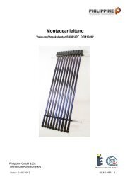
<strong>Assembly</strong> <strong>instructions</strong><br />
Evacuated- tube solar collector SUNPUR ® OEM10/2DF<br />
Philippine GmbH & Co; Status:21/04/2011<br />
OEM10DF -1
Table of contents<br />
1. Introduction P. 3<br />
Safety <strong>instructions</strong> P. 3<br />
System tips P. 6<br />
Planing sheme for maintenance P. 7<br />
2. Roof installation<br />
Roof mounting set, parts list P. 8<br />
Connection set, parts list P. 9<br />
Substructure for tiled and pantiled roofing P. 9<br />
Installation on corrugated eternit or trapezoidal sheet roofs P. 11<br />
Collector installation on sloped roofs P. 12<br />
Flat roof elevated mounting P. 13<br />
Installation on flat roofs and facades P. 14<br />
General information P. 15<br />
3. Collector installation P. 16<br />
Collector field connection P. 17<br />
Vacuum tube replacement or rotation P. 18<br />
4. Commissioning and filling P. 19<br />
5. Technical data P. 20<br />
Appendix<br />
Warranty conditions P. 21<br />
� Technical modifications which serve to enhance the product or related accessories are<br />
reserved.<br />
� The most current version of the installation instruction and additions as informations of<br />
ststics can be downloaded at www.sunpur.de.<br />
OEM10DF -2
1. Introduction<br />
These <strong>instructions</strong> give important details for installing the SUNPUR ® OEM collectors and their installation<br />
and connection systems.<br />
The specialist company responsible for installation must also comply with applicable regulations while<br />
observing engineering standards.<br />
The dimensions contained in these <strong>instructions</strong> are only guideline indications taken from common<br />
practice. The specialist company is responsible for installed dimensions of the equipment.<br />
Philippine GmbH & Co. Technische Kunststoffe KG is not liable for the dimension details contained in<br />
the commercial range of equipment, as not all technical general conditions (snow load zones, building<br />
height, wind loads etc.) can be coordinated in the framework of a general product range. We would be<br />
happy to advise you in detailed project planning.<br />
The installing company has to ensure that the mechanical durability of the interface connections to the<br />
building shell is guaranteed, in particular, for its leak-tightness.<br />
Philippine GmbH & Co. Technische Kunststoffe KG components are designed according to anticipated<br />
loads and the current state of technology.<br />
Before starting installation please consider our guarantee terms on page 23.<br />
Technical changes which improve product quality or ease of assembly do not constitute grounds for<br />
complaint.<br />
Safety <strong>instructions</strong><br />
Terms and symbols used<br />
"WARNING"<br />
This term and lettering will be used in conjunction with potentially hazardous situations, which could lead to<br />
severe bodily injury or death.<br />
"CAUTION"<br />
This term and lettering will be used in conjunction with potentially hazardous situations, which could lead to slight<br />
bodily injury or to material damage.<br />
This symbol will be used when the risk of injury or system damage is present if <strong>instructions</strong> are not<br />
complied with.<br />
This symbol will be used when the risk of burning is present if hot surfaces or scalding liquids are<br />
contacted.<br />
This symbol will be used when the risk of injury is present due to stumbling or falling.<br />
This symbol will be used when the risk of injury is present due to falling objects.<br />
OEM10DF -3
Product safety and risks<br />
This product is built to state of the art in agreement with the approved technical safety regulations. Despite this,<br />
there are still risks using this product.<br />
There are risks, for example, through heating up of assembly parts of the solar collector during its operation. There<br />
are other risks through breaking of glass (injury of cuts), spurting hot fluid and flowing steam (burning) or through<br />
falling when working on the roof.<br />
The evacuated-tube solar collector OEM 10 must be put into operation and used only under flawless condition and<br />
consideration of this instruction manual. It may be used only for the described purpose. If used for another purpose<br />
as described (misused), there are risks for persons and the solar collector can be damaged. Misuse of this product<br />
can be, for example, filling the collector with another substance than the approved heat transfer medium or<br />
assembling on surfaces that are insufficient in stability.<br />
Arbitrary alterations and changes apart from those described in the instruction manual are not permissible.<br />
The evacuated-tube solar collector OEM 10 must be mounted and operated according to the approved technical<br />
regulations. The respective national safety laws for employment protection and prevention of accidents must be<br />
carefully regarded and kept. This is especially imperative for work on the roof.<br />
Lightning protection: All electrical equipment items with a metal housing shall be earthed. This is also true for solar<br />
systems. The pump set, pipes, reservoirs and collectors must be provided with a potential equalisation, viz. be<br />
connected to earth just like any standard water pipe. Earthing requires a strongly conductive contact between the<br />
earthing point and the collector. The earthing clips can be installed at the collector frame. The solar circuit pipeline<br />
system shall be connected to the building’s potential equalisation over short runs both, for the feed and the return<br />
lines.<br />
Caution! The glass tubes are of the vacuum type. Damage, external pressure, loading or twisting, application of<br />
concentrated loads or force impact may cause implosion. Flying glass fragments may cause injuries. Removal or<br />
disposal to be done by specialist companies only. All materials used are recyclable.<br />
Solar systems should be maintained or services by duly licensed heating contractors, and mainly includes the heat<br />
transfer medium; collectors are merely subjected to visual inspection. Collectors should be replaced if damaged or<br />
if there is loss of vacuum. Isolated tubes shall not be replaced on site.<br />
Owing to its nano coating on the vacuum tubes, the collector is self-cleaning. However, should there be major<br />
contamination; the collector may be cleaned with water. Do not use any industrial cleaners based on abrasive<br />
cleaners.<br />
Roof installation safety <strong>instructions</strong><br />
CAUTION, RISK OF BURNING!<br />
Collectors can become extremely hot when exposed to solar radiation. Risk of burning upon contact!<br />
After unpacking the collector, do not expose it to solar radiation for a lengthy period without<br />
protection. Carry out the roof installation only on a cloudy day or ensure the collector is adequately<br />
covered.<br />
If possible, remove the collector from its packaging only after all mounting elements have already been installed on<br />
the roof. If multiple collectors are to be installed, remove only the respective collector being installed from its<br />
packaging before unpacking the next one.<br />
WARNING, RISK OF FALLING!<br />
A risk of falling exists anytime work is being performed on the roof, as well as when climbing up<br />
to, or down from the roof. Heed accident prevention regulations at all times and use appropriate<br />
fall protection devices.<br />
OEM10DF -4
WARNING, RISK OF INJURY!<br />
When performing installation work on roofs, there is the danger of tools, installation material or the<br />
collector, itself, falling from the roof and causing injury to persons below. Prior to beginning<br />
installation work, cordon off the danger area on the ground and warn any persons present in the<br />
vicinity or in the building.<br />
Unauthorised persons must not be allowed to climb up on the roof.<br />
Please use work glove for the assambling to avouid injury.<br />
Who can install collectors?<br />
Ensure that children are kept clear of the area.<br />
Installation planning, roof installation and commissioning of the Vacuum tube collector OEM 20/2DFI must be<br />
carried out only by those persons who, based on their professional qualifications, are familiar with the proper and<br />
safe execution of the installation process (specialized craftsman such as a roofer and/or a licensed heating<br />
technician).<br />
Two persons are required for roof installations.<br />
Installation prerequisites<br />
WARNING, RISK OF INJURY:<br />
When collectors are installed roofing where a stable attachment is not completely warranted, there is<br />
the risk of it coming loose, for example during a storm or due to heavy snow loading, and being<br />
damaged, damaging the roof or falling from the roof and injuring someone below. The collector must<br />
be mounted only on roofing, on which a stable and reliable attachment is warranted.<br />
Attention! Glass tubes are vacuum pressurised. Damage, external pressures, loading or torsion,<br />
localised stresses or violent forces will lead to an implosion. Injuries can result from flying bits of<br />
broken glass.<br />
OEM10DF -5
System tips / planning<br />
The following points must be considered when planning the system:<br />
• How much power will be consumed over what period of time?<br />
• Is the demand continuous (weekends, holiday season)?<br />
• How much power must be stored over what period of time in order to bridge those<br />
periods, in which energy take-off does not occur?<br />
• Can an alternative energy usage, such as pool heating, solar cooling, heating networks,<br />
etc., be introduced?<br />
• What is the current supply/return temperature of the heating system in use?<br />
• Is floor heating/wall heating available?<br />
• Combinations with domestic water heating?<br />
• Arrangement of the collector field, installation variants?<br />
• Line lengths, cross-sections and material composition<br />
� Max. operating temerature is 140°C.<br />
� The statics of every installation has to be prooved locally.<br />
� Recommended diameter of the risers for a warm water support plant (3 solar collector panels) = DN<br />
16. Pump recommendation 25/4 or 25/60<br />
� Recommended diameter of the risers for a heating support plant (6 solar collector panels) = DN20.<br />
Pump recommendation 25/80.<br />
� Recommended diameter of the risers for a heating support plant (8 collectors) = DN20 made of<br />
stainless steel corrugated tube or 18 mm copper tube. Pump recommendation 25/80.<br />
� For a heating support plant, 130 litres of buffer volume should be provided for each collector. There<br />
will be a risk of stagnation if the buffer volume is less.<br />
� Volume flow rate: The volume flow rate will be a function of the temperature level that is to be<br />
operated within the system. A volume flow rate of 0.5 to 1.0 litre/m²*min. in relation to the aperture<br />
area is recommended.<br />
� The flow velocity in the tubes should not be any larger than 1 m/sec. to avoid excessive pressure<br />
loss. We recommend 0.3 to 0.5 m/sec.<br />
� These values relate to the overall pipe length of the system of max. 2 x 20 m.<br />
� These values are merely standard values and should be precisely determined for a specific<br />
application.<br />
The flow resistance in corrugated stainless steel piping is considerably higher than in<br />
copper piping. This must be considered when dimensioning the pump.<br />
Corrugated stainless steel pipes must not be laid horizontally, as otherwise air bubbles<br />
will form that cannot be removed from the system, even during the flushing process.<br />
� Do not install small radii in the pipes. Rather use bends of 2 x 45 degrees instead of merely one<br />
bend of 90 degrees.<br />
� The solar station to the collector system merely accepts high-temperature fittings or insulation. In<br />
the event of stagnation, the pipes may heat up to more than 130°C.<br />
OEM10DF -6
For soft twin copper tube, make sure the cross-section does not get too small from bending.<br />
This would bring about a strong increase in the flow resistance.<br />
� The collector sensor should be installed with thermal compound.<br />
� Several collector sensors should be provided for larger fields of collector panels so that the solar<br />
control system will promptly react to the field condition.<br />
� The solar control system for external collector sensors should have interval control so that the<br />
sensor will be able to determine the temperature actually prevailing within the field of collector<br />
panels.<br />
Setting: e. g. from 08:00 to 18:00 hours, the pump is to run approximately five seconds at intervals<br />
of five minutes each.<br />
If more than 3 OEM 10/x collectors are to be switched in series, particular attention<br />
should be paid to pump dimensioning.<br />
2 collectors in line<br />
2 x collectors<br />
1 x connecting -set 2 in serieal<br />
1 x roof assembling 2-fold<br />
(dependent on roof covering<br />
6 collectors<br />
6 x collectors<br />
3 x connecting -set 2 in serieal<br />
2 x roof assembling 2-fold<br />
(dependent on roof<br />
6 collectors<br />
6 x collectors<br />
1 x connecting -set 3+3<br />
2 x roof assembling 3-fold<br />
(dependent on roof covering<br />
Planing sheme for maintenance<br />
If a collector has to be changed,there is a space of<br />
min. 20 cm required.<br />
(picture showes flat roof mounting)<br />
3 collectors in line<br />
3 x collectors<br />
1 x connecting -set 3 in serieal<br />
1 x roof assembling 3-fold<br />
(dependent on roof covering<br />
8 collectors<br />
8 x collectors<br />
2 x connecting -set 4 in serieal<br />
2 x roof assembling 4-fold<br />
(dependent on roof covering<br />
40-50cm<br />
OEM10DF -7<br />
min.<br />
20cm
2. Roof installation<br />
� Tiled & pantiled roofing<br />
Interlocking roof tile<br />
Flat roof pantile<br />
� Corrugated eternit or trapezoidal sheet roofing<br />
(not within the scope of delivery )<br />
� Sloped roofs<br />
Roof mounting set, standard<br />
Description<br />
� Flat roof elevated mounting<br />
Bill of materials, roof installation kit,<br />
OEM 10/x collector<br />
� Roof hooks<br />
� Stainless steel bolt with fan nut<br />
� Cross- profile 40 x 40<br />
� End Cap<br />
� Phil. stop angle for collector<br />
� Profile connector set<br />
4-fould<br />
1,62 m<br />
3- fold<br />
2,44 m<br />
2- fold<br />
3,24<br />
Pcs. Pcs. Pcs.<br />
Hook roof 6 6 4<br />
Beam section Solo 05 cut to a length of 1.22 m each 2 4 0<br />
Beam section Solo 05 cut to a length of 1.62 m each 0 0 2<br />
Beam section Solo 05 cut to a length of 2.02 m each 2 0 0<br />
Philippine collector hooks 16 12 8<br />
Plastic end caps for Solo 05 section 4 4 4<br />
Hexagon head bolt M10x 25 acc. to DIN 933 A2 8 8 6<br />
Hexagon flanged nut with stop teeth M10 acc. to DIN 6923 A4 24 20 14<br />
Half-countersunk bolt M10*30 toothed for collector hook 16 12 8<br />
Section connector for beam section 2 2 0<br />
Instructions for installation SUNPUR 1 1 1<br />
OEM10DF -8
Standard connecting set<br />
List of items for connecting set OEM<br />
solar collector panels 10/X<br />
Piched roof fastening – falsework<br />
For classical pitched roof fastening, two rows of roof hooks, resp., roof-fastening<br />
elements will be fixed on the roof’s supporting substructure per solar collector panel<br />
rows The cross beam profile is fixed on these elements. Two cross beams each<br />
carry a module row, which is aligned and fastened over 4 collector hooks each on the<br />
cross beam. The solar collector panels are installed perpendicularly<br />
Horizontal slanted roof<br />
mounting<br />
facde mounting<br />
Connection<br />
3+3<br />
Connection<br />
4 in a row<br />
Vertical slanted roof<br />
mounting<br />
Connection<br />
3 in a row<br />
Connection<br />
2 in a row<br />
Description Pcs. Pcs. Pcs. Pcs.<br />
Connecting pipe left/right 1 m insulated,<br />
including nozzle size 15 on either end 2 2 2 2<br />
Bracket, cutting ring, 15 mm 1 1 1 1<br />
Connecting pipe 1 m insulated, size 18<br />
nozzle on either end 1 0 0 0<br />
T-piece cutting ring 15-15-15 1 1 1 1<br />
Carrying bracket size 15 for copper tubing 12 8 6 4<br />
Double cutting ring bolted connection 15-15 4 3 2 1<br />
Sensor sleeve 6 mm for size 15 cutting ring 1 1 1 1<br />
T-piece cutting ring bolted connection 15-<br />
18-15 1 0 0 0<br />
Flat roof mounting<br />
without brackets<br />
OEM10DF -9
Crossmember profile connection<br />
In order to connect the crossmember profiles, insert the bolt into the connector from above and slide it through the<br />
crossmember profile, ensuring the hexagon bolt head does not wedge into the rectangular slot. Slide the connector<br />
up to halfway and bolt it in place. Repeat the step with the second crossmember. There must be no gap between<br />
the crossmember profiles.<br />
Substructure for tiled and pantiled roofing<br />
Standard roof hooks are used for interlocking roof tiles or pantiles, while special roof hooks are available for special<br />
tile forms.<br />
Tool tip: Handy angle grinder with small diamond grinding wheel, socket wrench insert #13 with ratchet, drill<br />
with socket insert and torque limiter, brush with some grease for wood bolts, drill with 6 mm drill bit<br />
1. Determining the position of the cross beam<br />
The cross beam should run inserted about 1/5 of the height of the module<br />
from upper and lower module edge. Pay attention to the position of the tile<br />
for ventilation! The position of the cross beam for overlapping module rows<br />
is to be aligned with the roof tile rows.<br />
min 0,5 m<br />
min 0,5 m<br />
2. Select roof hooks and place them<br />
The roof hooks are placed perpendicularly according to the desired position<br />
of the cross beam. For the horizontal position: Normally a roof hook is<br />
placed on every second rafter. A roof hook is recommended each for the first<br />
two rafters in order to compensate for the strain through wind turbulence. A<br />
maximum of 0.4m should be projecting left and right of the cross beam.<br />
Maximum roof hook space is 1.8m. Place a hook on every rafter for areas<br />
with increased snow or wind exposure, or enquire about the exact guideline<br />
1.60 - 1.80 m<br />
values from the manufacturer (Note: different sizes of roof hooks are<br />
available!). Stronger roof hooks are recommended for module heights above<br />
1.6m! Adjustable roof hooks help the adjustment of height for uneven roofs.<br />
For very broad roof tiles, “right” roof hooks can be used additionally to the<br />
“left” standard hooks for the installation. A further extreme balance in the horizontal position can follow<br />
through the combination.<br />
3. Fixing the roof hooks<br />
The roof tile is pushed up. The bar of the roof hook lies perpendicularly or in the flat level of the roofing tile.<br />
Between tile and bar there shall be at least 5 mm space, if necessary, it is on the base plate of the roof hook<br />
accordingly. A sheet metal pan suitable for the roof tile form is generally recommended under every roof hook<br />
for expected snow weight and especially for pan tiles! The roof hooks are fixed on the rafters with at least 2<br />
screws -8mm, ca. 2/3 of the whole screw length, pre-bored. Pay attention that at least 70mm of the screw is in<br />
the rafter – if necessary, use longer screws! Lubricating the screws with grease avoids shearing when<br />
screwing in. The bar of the roof hook can be secured, if desired, with a rubber ring against forcing up of water<br />
from strong wind.<br />
OEM10DF -10
4. Replace covering tile<br />
Depending on the form of the roof tile, sanding may be necessary (use angle grinder with diamond disc!) so that<br />
the tile can be closed together with the roof hooks.<br />
5. More under “collector installation” (point 3)<br />
Hints from professionals: The fastening screws on the raft are extremely important for the entire static.<br />
pax-screws are not to be recommended because of the weak cross section on the<br />
head! Make sure that there is sufficient screw length for the counter-battens!<br />
Hints from professionals: Caution is necessary when very flat roofs are to be fitted with roof hooks! The<br />
installer of the collector can be made liable for possible subsequent leakage.<br />
Therefore it is necessary to know that tile manufacturers can guarantee only<br />
restrictedly for leak tightness with flat roof sloping.<br />
Following citing from a renowned tile manufacturer should help to recognise problems.<br />
Interlocking tile<br />
� Is normally recommended up to a minimum of 30 degrees<br />
� Is only recommended in special cases (tight sarking membrane, if necessary pasted) up to 24 degrees<br />
Flat roof tiles MZ3<br />
� Is normally recommended up to a minimum of 22 degrees<br />
� Is only recommended in special cases (tight sarking membrane, if necessary pasted) up to 16 degrees<br />
OEM10DF -11
Installation of corrugated cement asbestos panels or trapezoidal<br />
sheet metal roofs hanger bolt (hanger bolt installation)<br />
Tool- hints: Combination wrench SW 18, bore machine, if necessary additional nuts M12 for countering.<br />
Hanger bolts with wrench size, also heavy-duty screwdriver with insert piece 9mm or 8mm<br />
(depending on the type)<br />
So-called corrugated fastening elements consisting of special hanger bolts and a mounting plate are<br />
used for corrugated cement asbestos panels or trapezoidal sheet metal roofs (see pictures). They are<br />
placed perpendicularly according to the desired position of the cross beam. For the horizontal<br />
position: A fastening set is placed at least on every second rafter of the subconstruction. A maximum<br />
of 0.4m should be projecting left and right of the cross beam. Maximum fastening space is 1.6m. In<br />
areas with increased snow and wind exposure or by weak rafters (as used on plate covered roofs),<br />
place a fastening element on every rafter or enquire about the exact guidelines from the<br />
manufacturer. Normally a fastening set with a hanger bolt M12x300 is recommended. For special<br />
fastening types with lesser cross-distance, a version M10x200 is available.<br />
Fastening assembly sets<br />
The roof skin is bored on the appropriate places (hole diameter 14mm with M12,<br />
13mm for M10 screws). The bores are not positioned in the water-bearing slots but<br />
in the elevations of the plate profile! The fastening bore is made in the rafter through<br />
the installation bore (8.5mm). The hanger bolt should be screwed into the rafter at<br />
least 80 to 100mm. The hanger bolt should be turned so that only the metric<br />
threading and if possible, a piece of the smooth shaft of the sealing seat is jutting out<br />
of the roof skin. Two nuts can be countered upon each other on the surface of the<br />
screw to turn in the screw (see picture). Lubricating the screw with grease makes it<br />
easier to turn in!<br />
Make the sealing and check it<br />
The gasket is pushed to the bottom for the sealing and lightly pressed with the flange<br />
nut onto the roof skin. Be careful when pressing on corrugated cement asbestos<br />
panels – danger of breaking!<br />
More under “collector installation” (point 3)<br />
OEM10DF -12
Solar panel assembly on pitched roofs<br />
Cross beam<br />
Collector installation systems contain only profiles with proven static characteristics! Please look up the<br />
permissible supporting spaces in the system static!<br />
Installation hints for roof installation set<br />
1. Screw and align cross beam on the fastening points<br />
Push screw (in the right M10x25) in the groove of the cross beam profile and place roughly in gaps. Insert the<br />
first cross beam (beginning with the first screw) in the fastening row (roof hook, corrugated roof fixtures, plate<br />
fold clamps). Secure the first screw with a nut on the roof’s fastening at best, lift the rails slightly bent and then<br />
insert the screws one after the other and secure with nuts (do not pull tight as yet!). Extend cross beam profile<br />
with connecting plate if necessary. Compensate uneven heights on the roof<br />
a) From tiled or pan tiled roofs: Use vertically adjustable hooks or longer M10-screws for fastening with<br />
underlay.<br />
b) Corrugated cement asbestos panels or trapezoidal sheet metal roofs: Fit mounting plates on the<br />
hanger bolt through adjusting the mounting nuts applicably.<br />
c) Use longer M10 screws with underlay for fastening if necessary.<br />
Tool- hints: Combination wrench SW 15<br />
2. Control and pull all screws of the subconstruction tight<br />
Finally, the lowest rail is aligned in a straight position. After fastening the lowest row of rails, mount the ther rails.<br />
Pay attention to the side for exact alignment with the roof covering.<br />
After aligning all the cross beam rails, pull all the connecting screws tight! Use only special nuts with locking profile!<br />
When connecting the plant to the lightning protection of the building, pay attention to the hints in the last section!<br />
OEM10DF -13
Flat roof elevation<br />
On a flat roof elevation, a module row of vertically aligned modules is normally<br />
fastened on a pair of cross beams. The pair of cross beams is in turn mounted on a<br />
row of supports. Most of the supports are available in different angles of approach: 30<br />
degrees yield the optimal annual degree of coefficiency, 45 degrees can optimise the<br />
yield of the island of panels in the winter half year, 20 degrees can be used as<br />
additional positioning on slightly sloped flat roofs. The cross beam profile is fastened<br />
on the supporting elements. Two cross beam profiles each normally carry a module<br />
row, which is aligned and fastened over the end and middle clamps on the cross<br />
beam. Special arrangements of modules are equally possible. Different types of<br />
supports allow the adjustment suitable to the different condition.<br />
Terms of reference of flat roof brackets<br />
Screwed angle support<br />
Screwed angle supports are used when the plant can be screwed<br />
directly on the ground or on a cemented weight on the flat roof.The<br />
standard angle-connecting piece is especially suited for larger<br />
modules. It is available in longer measurements for special usage on<br />
request (e.g. also for two rows module installation).The Prof. angle<br />
connecting piece is intended for normal cases of use.<br />
1. Mount the support and place on the roof surface. The lateral distance of the<br />
connecting support is to be selected according to the boundary conditions (building<br />
height, snow load, wind exposure, module height). 1.6 up to 1.8m is normally used.<br />
The lateral projection of the profile should be max. 0.4 to 0.5m.<br />
2. Fixing the supports.<br />
Collector quantity 2 3 4 5 6<br />
Quantaty brackets/ AL gravel pit tray 2 2 3 - 4 (3+3)<br />
� For installation on concrete elements: Bolt the supports up on<br />
the elements one by one.<br />
� For installation on a gravel trough: Bolt the supports up<br />
on the gravel trough one by one.<br />
3. Arrange supports in a row<br />
4. Fasten cross beam on the supports loosely<br />
Push the screw in the groove of the cross beam profile and distribute in rough<br />
spaces according to the space of the supports. Then fasten the first cross beam<br />
piece (beginning with the first screw) in the first connecting piece loosely. Then<br />
gradually line up the supports one after the other. Connect cross beam with<br />
connecting plate on the lowest side; the connection can be done on the support on<br />
standard angle supports. After aligning all the cross beam rails on the supports, pull<br />
all the connecting screws tight! Use only special nuts with locking profile!<br />
5. Place the frame, if necessary, in the right position<br />
6. Alle Schrauben der Unterkonstruktion fest anziehen bzw.<br />
kontrollieren<br />
7. For installation on a gravel trough only: Load the trough with gravel.<br />
8. Proceed as described at “Installation of collectors“ (section 3).<br />
OEM10DF -14
List of items for flat roof and facades mounting set for<br />
SUNPUR OEM10DF<br />
Flat roof and facades mounting<br />
Mounting elements comprised of a hanger bolt and a mounting plate<br />
(see pictures) are used on flat roof or façade installations. They are<br />
distributed in two series (for several overlapping collector fields, two<br />
series per field) according to the desired crossmember positions. The<br />
crossmembers should be spaced at 1.60 meters. The mounting plate<br />
spacing should be a maximum of 1.40 metres. The crossmember<br />
should project out no more than 0.4 m at the ends.<br />
Mounting set attachment<br />
2-fach<br />
1,62 m<br />
1.6 m<br />
max. 1.4 m<br />
Either hanger bolts for direct mounting to the flat roof or a loading construction is used for<br />
attaching the crossmember profiles. The loading construction is secured with concrete<br />
blocks. Observe the allowable roof loading.<br />
For façade installations, the bolts are screwed directly into the façade. Drill 12 mm holes for<br />
hanger bolts and use 12 dowels. The hanger bolt should be screwed in at least 80 to 100<br />
mm.<br />
The crossmember profile is fixed to the mounting plate with bolts (generally M10x25). Push<br />
a bolt into the crossmember profile narrow square groove, insert into the first plate and<br />
secure with fan nuts (do not tighten). Push the remaining bolts into the profile and plug into<br />
the mounting plate. Secure bolts with nuts (do not tighten yet). Straighten the profile and fix<br />
with the fan nuts.<br />
For the highest possible yield we recommend horizontal installation with rotated tubes<br />
3-fach<br />
2,44 m<br />
4-fach<br />
3,24 m<br />
Description Pcs. Pcs. Pcs.<br />
Beam section Solo 05 cut to a length of 1.22 m each 0 4 2<br />
Beam section Solo 05 cut to a length of 1.62 m each 2 0 0<br />
Beam section Solo 05 cut to a length of 2.02 m each 0 0 0<br />
Philippine collector hooks 8 12 16<br />
Plastic end caps for Solo 05 section 4 4 4<br />
Hexagon head bolt M10x 25 acc. to DIN 933 A2 6 8 8<br />
Hexagon flanged nut with stop teeth M10 acc. to DIN 6923 A4 14 20 26<br />
Half-countersunk bolt M10*30 toothed for collector hook 8 12 16<br />
Section connector for beam section 0 2 2<br />
max. 0.4 m<br />
OEM10DF -15
General <strong>instructions</strong><br />
� All supports are statically calculated in relation to the boundary conditions (building height, snow load zones,<br />
module height, etc.). The permissible spaces for the supports are to be taken from the system static.<br />
� Make sure that the subconstruction can carry the additional roof load with regard to the snow.<br />
� Be aware that very large concentrated forces can turn up on the elevations on the fastening points with regard<br />
to the wind strain. For a combination of supports with fastening elements (e.g supports on hanger bolts,<br />
clamps, etc.) a proof of stability for the type of static must be done since these cases could not be listed in<br />
general system static. Likewise, a proof of static stability is to be carried out on the site.<br />
� The necessary loading for the force of gravity fastenings can be taken from the system static. It is important to<br />
note here that the roof-subconstruction must be able to carry the weight of the PV-plant additionally to the<br />
necessary load weights.<br />
� The static calculations of the supports are related to the vertical loads and not to the individual sides and tilting<br />
stability. It must be decided from case to case, whether the connecting supports can be made stable through<br />
additional diagonal bracings or similar.<br />
� Very often, only a force of gravity fastening without penetration of the roof skin is possible with dense roof skin.<br />
In these cases, special attention must be paid that building protection mats are used under the supports and<br />
that no stone from the gravel deposits or similar remains under the weights that can damage the roof skin.<br />
� Lightning protection: Fundamentally, all electrical equipment must be grounded with a metal housing. This is the<br />
same for the solar plant. Pump groups, pipelines, storage and collectors must have a potential equalisation,<br />
i.e. exactly as the normal water pipes which are connected to the earth. The grounding demands a very good<br />
conducting contact between the grounding point and the collector. The installation of the grounding clamps<br />
can be done on the collector frames. The solar circuit pipeline system is to be connected to the front as well as<br />
the back on short paths with the building’s potential equalisation.<br />
OEM10DF -16
3. Solar collector assembly<br />
Assemble the first collector<br />
On the floor<br />
1. Unpack the first collector.<br />
2. Subject the collector to visual inspection externally.<br />
The collector should be installed if intact and undamaged only. If it is<br />
damaged, report the damage to your retailer without undue delay.<br />
3. Insert the four collector hooks, two on the left and two on the right,<br />
into the longitudinal bars of the collector by means of the halfcountersunk<br />
bolts. The hooks should be installed so as to open downwards. To<br />
achieve this, insert the half-countersunk bolts into the hook and push into the<br />
longitudinal bar with the nut tightened by approximately two thirds (2/3). Use the<br />
angled “nose” as a calibration. Turn the half-countersunk bolt by one half turn<br />
(use a screwdriver) and use a box wrench to tighten the nut. Securely tighten the<br />
upper collector hooks at the same distance from the collecting case. The<br />
overhang is described in the chapter “Roof installation kit“ (item #2).<br />
Approximately one fifth (1/5) of the module height. Insert the bottom hooks slightly<br />
higher and merely tighten hand-tight such the collector can be mounted onto the<br />
two cross beams (step #5).<br />
On the roof<br />
4. Push one hexagon nut each with the nut tightened by approx. one half<br />
into the upper and the lower cross sections. Circumstances permitting, start<br />
installing the field of collector panels on the left hand side. The clearance to the<br />
outer cross beam edge should be approx. 1 cm.<br />
5. Mount the first collector onto the cross rail.<br />
6. Slightly undo the two bottom hooks and push downwards against the<br />
lower cross section, and securely tighten.<br />
7. Bolt the two outer collector hooks with the inserted hexagon bolt and the<br />
serrated nut to the cross section. Do this for the outer left collector hook only.<br />
(fixed bearing) All other collector hooks are merely hung into the beam section (movable bearing).<br />
8. Now, insert the carrying brackets in both collector terminals.<br />
Please insert flush left only.<br />
9. Now, slip the double crimp ring bolted connection from the<br />
connection kit onto the right copper tube.<br />
OEM10DF -17
Set the second collector<br />
1. 1-3 like the first collector<br />
2. Lay the second collector on the cross rails and hook it in.<br />
3. Insert both carrying brackets. Please insert flush left only.<br />
4. Push the collector against the first collector and make sure the double<br />
crimp ring bolted connection fits onto the copper tube of second collector<br />
without jamming.<br />
5. Slightly undo the two bottom hooks and push downwards against the<br />
bottom cross section, and securely tighten.<br />
To install three collectors in series, please repeat the procedure described at<br />
>Fixing the second collector
4. Setup and promptly filling<br />
Setup<br />
The collector can only be put into operation when it is free of air and must be deaerated again a few<br />
days after it has been in operation. An incomplete deaerated solar circuit can lead to grave disturbance<br />
in function! The collector may be operated only in a closed solar circuit. The collector may be filled and<br />
operated only with heat transfer mediums listed under "technical data". It should not be filled or<br />
operated with water.<br />
The compensation tank used must be set for 8 to 10 litres per module. For larger plants, a pre-tank may be<br />
necessary in front of the compensation tank. Please consult your systems partner on this.<br />
Up to 3 evacuated-tube collectors OEM 10 can be switched in a row as described. For the assembly of more than 3<br />
collectors in a field, they must be switched parallel with each other.<br />
For a parallel switching, more fields must provide for an equal distribution of flow in the single fields. The common<br />
switching for this, according to Tichlmann, is not normally sufficient for the smaller, single fields, since the pressure<br />
reduction is too less in the fields and the danger exists that a field cannot be properly flown through. We<br />
recommend therefore, a fixed or adjustable restrictor at the field output on the assembly.<br />
The path to the safety valve must always be opened. Only in this way, can arising impermissible high pressure be<br />
avoided. Make sure that the safety valve has an opening pressure of maximum 10 bars.<br />
Standard pumps are mostly equipped with safety valves up to 6 bar.<br />
The collector system is generally very hot in idle condition. temperature of over 100° C in the pipelines can occur in<br />
the basement. Please use appropriate solid temperature elements.<br />
OEM10DF -19
Filling<br />
The evacuated-tube collector OEM 10 DF may only be filled with undiluted heat transfer medium LS (made by<br />
Tyforcor) or Fernox Solar S1, promptly.<br />
Please consult the respective safety data sheets of the Tyforcor company. To fill and set up the<br />
plant, please pay attention to the <strong>instructions</strong> of your systems partner.<br />
If the empty collector gets very hot, it can be damaged. The solar circuit may therefore, not be filled if the collector is<br />
set out to direct rays from the sun or was shortly in the sun. Cover the collector at least an hour before if necessary,<br />
so that it can cool down.<br />
Before setting up the plant, a leakage test must be carried out and the collector (and solar circuit) must be<br />
completely deaerated. Manual filling pumps are not suitable, a jet pump (min. 800W. 40m conveying height) is<br />
necessary. The fill pressure should lie over 0.5 bar pressure in the compensation tank.<br />
The pump shall run at least 30 minutes before for pre-deaeration and be switched on and off several times.<br />
Thereby the heat transfer medium shall run into a container through a boiler, filling and emptying plug valve (KFEplug<br />
valve) built in the return line between heat exchanger and circulating pump and from there repressed with the<br />
jet pump back into the system.<br />
The plant is then deaerated if no air bubbles are visible in the heat<br />
transfer medium return flow.<br />
The following filling and flush fitting has proven to be good for the<br />
deaeration:<br />
The solar circuit can be filled after this. Follow all the steps of the<br />
manual of your systems- partner.<br />
5. Technical data (OEM10/2 Kollektor)<br />
Dimensions in mm 2120 x 775 x 110<br />
Performance η0 0,781<br />
k1 1,12<br />
k2 0,004<br />
Aperture surface (Ac) in m² 1,012<br />
gross surface in m² 1,628<br />
Max. operating time in bar 6<br />
Max. idle temp. in °C 296<br />
Max. operating temerature1 In °C 140<br />
Fluid vol. in l 1,49<br />
Weight in kg 26,8<br />
Spec. heat capacity Ws/m2/K 12.600<br />
Housing material PU-hard<br />
Frame AL-Profile<br />
Optical loss<br />
Conversion factors % 78,1<br />
Angle correction 97,0<br />
Kb50°longi 0.88<br />
Fig. 13: Fill and flush fitting<br />
OEM10DF -20
Terms of guarantee for SUNPUR ® tube collectors<br />
� These <strong>instructions</strong> for installation provide you with useful information regarding the assembly and installation<br />
of the fastening systems made by Philippine GmbH & Co. Technische Kunststoffe KG.<br />
� In addition to these <strong>instructions</strong>, the installation contractor shall observe and comply with any applicable codes<br />
or engineering standards.<br />
� The information contained in the <strong>instructions</strong> for installation in relation to dimensioning or hydraulic<br />
interconnection are merely practical pointers. The planning engineer shall accept responsibility for the<br />
configuration.<br />
� The installation contractor will be responsible for the mechanical stability and strength of the installed interface<br />
connections at the building envelope, and more specifically for their tightness.<br />
To achieve this, the components made by Philippine GmbH & Co. Technische Kunststoffe KG have been<br />
designed according to the expected loads and latest engineering standards.<br />
� No responsibility will be accepted for any defects caused by third parties, specifically through improper<br />
assembly, installation or commissioning, through faulty or negligent handling, through improper transportation,<br />
excessive use, improper equipment or resources, faulty construction work, inadequate ground or subsoil, or<br />
through improper operation or use.<br />
� Philippine GmbH & Co. Technische Kunststoffe KG will extend warranty pursuant to legal requirements and<br />
will accept liability for compensation for damages, however only in instances of intent or gross negligence.<br />
The German product liability law (ProdHaftG) shall apply in the event of injuries or damage to property arising<br />
from faulty product.<br />
The following guarantees will be extended beyond statutory warranty:<br />
� We warrant the good working order and operability of the collector modules as well as the tightness of the<br />
vacuum tubes for a period of five (5) years.<br />
� On top of that and subject to the proviso of proper handling and dimensioning under normal ambient and<br />
environmental conditions, we warrant a useful life and durability of the framework for a period of ten (10)<br />
years.<br />
Warranty will be extended subject to the following requirements:<br />
� Warranty will be extended subject to proper assembly and installation and evidence of the annual servicing of<br />
the whole system including the heat transfer fluid.<br />
� The ambient temperature of the collector should not be below –40 °C or above +85 °C respectively.<br />
� After removing the protective wrapping from the items made by Philippine (collectors, roof installation kit,<br />
connecting kit), inspect the items to detect or exclude visible flaws (apparent defects).<br />
Complaints should be reported without any undue delay to your dealer or direct to Philippine GmbH & Co.<br />
Technische Kunststoffe KG at the below number.<br />
Service hotline: +49 (0) 26 21 - 173 0<br />
E-mail: vksolar@philippine.de<br />
OEM10DF -21
If the complaint is reported with an undue delay claims under guarantee will lapse.<br />
Warranty claims will lapse where defective items are installed by intent or negligence.<br />
Moreover, only Philippine OEM installation or connection parts may be used.<br />
Warranty will also lapse where the customer performs interventions and/or has repairs on Philippine items<br />
performed by unauthorised persons without express written consent.<br />
Minor discolorations on plastic components during their service life will not affect or impair product quality or<br />
performance and will not be eligible for warranty claims.<br />
Warranty processing<br />
In the event of a warranty claim, and after inspection, a replacement collector will be sent to the customer freight<br />
paid.<br />
The defective collector will be returned cost-neutral for Philippine GmbH & Co. Technische Kunststoffe KG or<br />
picked up to a charge.<br />
No consequential costs, specifically costs of installation, will be accepted unless this should be provided for by law.<br />
Please send bevor pictures and a short report of the damage bevor sending the goods to Philippine.<br />
Recommendation<br />
A building insurance or glass breakage insurance should be taken out for the collector system.<br />
Installation should be reported to the insurers. Some insurers may offer a specific insurance for solar systems.<br />
Please ask your insurance adviser.<br />
OEM10DF -22
OEM10DF -23
OEM10DF -24
OEM10DF -25