USERS OPERATING MANUAL RG5000-E - Advanced Engineering
USERS OPERATING MANUAL RG5000-E - Advanced Engineering
USERS OPERATING MANUAL RG5000-E - Advanced Engineering

You also want an ePaper? Increase the reach of your titles
YUMPU automatically turns print PDFs into web optimized ePapers that Google loves.
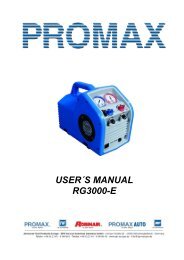
<strong>USERS</strong> <strong>OPERATING</strong> <strong>MANUAL</strong><br />
<strong>RG5000</strong>-E<br />
Amprobe Europe GmbH<br />
Lürriper Strasse 62<br />
41065 Mönchengladbach<br />
Telefon +49(0)2161/59906-0<br />
Telefax +49(0)2161/59906-16
AMPROBE EUROPE<br />
<strong>RG5000</strong>-E<br />
TABLE OF CONTENTS<br />
I) Safety precautions<br />
A) The safe way ist he only way! 1<br />
B) Refrigerant gas recovery & containment 2<br />
II) Important general information 3<br />
III)<br />
Operational procedures<br />
A) Operating your <strong>RG5000</strong>-E 4-6<br />
B) Set-up procedures 7-9<br />
C) Purging the non-condensable gases 10<br />
IV) Diagrams<br />
A) Part list 11<br />
B) Refrigerant flow diagram 12<br />
C) Wiring diagram 13<br />
V) Safety pressure switch 14<br />
VI) Care and maintenance 15<br />
VII) Technical data 16<br />
VIII) Repair Kits 17-18<br />
IX) Helpful hints 19-21<br />
X) Troubleshooting 22<br />
Design specifications and material are subject to change without notice. REV082002TWH<br />
This manual may not be reproduced in any way, shape or form without express written consent of<br />
AMPROBE.
AMPROBE EUROPE<br />
<strong>RG5000</strong>-E<br />
THE SAFE WAY IS THE ONLY WAY!<br />
NOTE! If you are not a qualified refrigerant service technician,<br />
do not use this equipment<br />
1. The technician should always wear goggles and gloves when working on<br />
refrigeration systems.<br />
2. Be sure that any room where you are working is thoroughly ventilated, especially if<br />
a leak is suspected. Refrigerant vapor is hazardous to your healthand can cause<br />
death.<br />
3. Always think before acting. Familiarity breeds carelessness and carelessnesscan<br />
be harmful to your health or, worse, result in death.<br />
4. Read the Material Safety Data Sheets (MSDS) on all compounds with whichyou are<br />
likely to come in contact. Read MSDS on refrigerant and refrigerant oil. Obtain<br />
MSDS sheets from your refrigerant supplier.<br />
5. Never use oxygen when testing for leaks. Any oil in contact with oxygen under<br />
pressure will form an explosive mixture.<br />
6. Refrigerant systems are generally electrically driven and controlled. Be sure to<br />
disconnect the unit from the power source before servicing it.<br />
7. Always store refrigerant containers in a cool, dry place.<br />
8. Always open service and cylinder valves slowly. This allows quick control of the flow<br />
of gasses if there is any danger. Once it is determined that there is no danger, the<br />
valves may be opened fully.<br />
9. Do not mix refrigerant in a system, a tank or anywhere else. Each type of refrigerant<br />
must have its own tank, filters, etc.<br />
10. If moisture enters the refrigerant system, it is likely to cause considerable damage.<br />
Keep everything connected with the refrigeration system thoroughly dry and clean.<br />
11. To reduce the risk of fire, avoid the use of extension cords as they may overheat.If<br />
you must use an extension cord iit should be a minimum of 12 AWG and not longer<br />
than 15ft.<br />
This equipment should be used in locations with mechanical ventilation providing at<br />
least four air changes per hour, or the equipment should be located at least 45cm<br />
(18”) above the floor. Do not use this equipment in the vicinity of spilled or open<br />
containers of gasoline or any other flammable liquid.<br />
- 1 -
AMPROBE EUROPE<br />
<strong>RG5000</strong>-E<br />
REFRIGERANT GAS<br />
RECOVERY & CONTAINMENT<br />
Safety comes first. Read all safety information for the safe handling of refrigerant<br />
including the Material Safety Data Sheet provided by your refrigerant supplier. Never<br />
operate unit in an explosive environment. Wear safety glasses and protective gloves.<br />
Work area must be well ventilated. This unit should only be operated by a qualified<br />
technician.<br />
*** CAUTION: REFRIGERANT STORE CONTAINERS ***<br />
Use only approved cylinders that serve the current regulations.<br />
NOTE: Recovery cylinders are designed for different pressures. Do not exceed the<br />
working pressure of each cylinder.<br />
Safety codes recommend that closed tanks not be filled over 80% of volume with liquid.<br />
The remaining 20% is called head pressure room.<br />
NEVER TRANSPORT AN OVERFILLED CYLINDER.<br />
Refrigerant expands when it gets warm and may cause a tank to explode if overfilled.<br />
CYLINDER TEMP. 16 °C 21 °C 38 °C 54 °C 66 °C<br />
STARTING WITH<br />
CYLINDER 80%<br />
FULL BY VOLUME<br />
SPACE OCCUPIED<br />
BY LIQUID<br />
80 % 81% 83% 90% 94%<br />
STARTING WITH<br />
CYLINDER 90%<br />
FULL BY VOLUME<br />
SPACE OCCUPIED<br />
BY LIQUID<br />
90% 92% 96% 100%<br />
- 2 -
AMPROBE EUROPE<br />
<strong>RG5000</strong>-E<br />
IMPORTANT<br />
GENERAL INFORMATION<br />
Before operating the <strong>RG5000</strong>-E recovery unit, read the following:<br />
1. Always isolate large amounts of refrigerant and close off valves after use so if a<br />
leak should develop anywhere in the system the refrigerant does not escape.<br />
2. Storage cylinders sometimes have valves that are not properly seated when<br />
manufactured. Keeping caps on these valves will guard against refrigerant leakage.<br />
3. Always operate the unit on a flat level surface.<br />
4. Your <strong>RG5000</strong>-E has one internal pressure shut off switche. If the pressure inside<br />
the system should go above 27,5 bar (400 psi), the system will automatically shut<br />
itself off.<br />
CAUTION<br />
The 27,5 bar (400 psi) switch does not prevent tank overfill. If your system shuts<br />
off on high pressure and is connected to your tank, you may have overfilled your<br />
tank and created a very dangerous situation! Take immediate measures to relieve<br />
any high pressure and/or tank overfill.<br />
5. WARNING! Never overfill storage tanks. Overfilling may cause tanks to explode.<br />
6. A scale must be used to avoid overfilling the storage tank.<br />
7. Tanks and filters should be designated for one refrigerant only. Before using a tank<br />
previously used for another refrigerant, completely empty the tank, evacuate it,<br />
purge the tank using dry nitrogen, and re-evacuate it.<br />
8. Special care should be taken when recovering from a burned-out system. Use two<br />
high acid capacity filters, in series. Alco type EK-162-F or Sporlan type C-162-F are<br />
recommended.<br />
9. When you have finished recovering from the system, flush your <strong>RG5000</strong>-E with a<br />
small amount of refrigerant oil and a small amount of clean refrigerant to purge off<br />
any foreign substances left in the unit.<br />
10. Always empty refrigerant from the unit into a storage tank; see Self Purge/Auto<br />
Evacuate procedure. Liquid refrigerant left in the condenser may expand, causing<br />
damage to components.<br />
- 3 -
AMPROBE EUROPE<br />
<strong>RG5000</strong>-E<br />
<strong>OPERATING</strong> YOUR <strong>RG5000</strong>-E<br />
Connect your <strong>RG5000</strong>-E to a 230 V outlet. Switch the main power switch to the ON<br />
position. You should hear the fan running. Press the compressor start switch. This<br />
"momentary" switch will start the compressor. It may be necessary, under certain<br />
circumstances, to press this switch more than once to start the compressor.<br />
OPERATIONAL PROCEDURES<br />
NORMAL RECOVERY<br />
Do not turn this valve<br />
while unit is running.<br />
Close input valve, turn<br />
machine off, switch to<br />
Purge position and restart<br />
machine.<br />
SELF PURGE / AUTO EVACUATE<br />
Do not turn this valve<br />
while unit is running.<br />
Close input valve, turn<br />
machine off, switch to<br />
Purge position and restart<br />
machine.<br />
NOTE:<br />
To change from Recovery mode to Purge:<br />
Close the Input port, turn the unit off (to prevent high pressure shutoff),<br />
switch to Purge position and restart the unit.<br />
- 4 -
AMPROBE EUROPE<br />
<strong>RG5000</strong>-E<br />
<strong>OPERATING</strong> YOUR <strong>RG5000</strong>-E<br />
Procedure for Normal System Recovery<br />
1 Inspect the <strong>RG5000</strong>-E thoroughly to insure that it is in good operating condition.<br />
2 Make sure all connections are correct and tight.<br />
3 Open the liquid port of the recovery cylinder (always open valves slowly to check<br />
hoses and connections for leaks).<br />
4 Make sure the Recover/Purge valve is set on Recover.<br />
5 Open the output port of the <strong>RG5000</strong>-E.<br />
6 Open the liquid port on the manifold gauge set; opening the liquid port will remove<br />
the liquid from the system first, greatly reducing the recovery time (after the liquid<br />
has been removed, open the manifold vapor port to finish evacuating the system).<br />
7 Connect your <strong>RG5000</strong>-E to a 230 V outlet.<br />
a) Switch the main power switch to the ON position. You should hear the<br />
fan running.<br />
b) Press the compressor start switch. This "momentary" switch will start<br />
the compressor (it may be necessary, under certain circumstances, to<br />
press this switch more than once to start the compressor).<br />
8 Slowly open the input port on the <strong>RG5000</strong>-E.<br />
a) If the compressor starts to knock, slowly throttle back the input valve<br />
until the knocking stops.<br />
b) If the input valve was throttled back, it should be fully opened once the<br />
liquid has been removed from the system (the manifold vapor port<br />
should also be opened at this time).<br />
9 Run until minimum EPA required vacuum is achieved.<br />
a)Close the manifold vapor and liquid ports.<br />
b)Close the <strong>RG5000</strong>-E input port.<br />
c)Shut unit off and proceed with the Self Purge procedure on the next<br />
page.<br />
10 Always purge the <strong>RG5000</strong>-E after each use. Failure to purge the remaining<br />
refrigerant from the <strong>RG5000</strong>-E could result in the acidic degradation of internal<br />
components, ultimately causing premature failure of the unit.<br />
CAUTION<br />
When pumping liquid, do not allow the <strong>RG5000</strong>-E to operate with the input valve<br />
too far open, causing the compressor to knock. Doing so may stall the<br />
compressor<br />
- 5 -
AMPROBE EUROPE<br />
<strong>RG5000</strong>-E<br />
<strong>OPERATING</strong> YOUR <strong>RG5000</strong>-E<br />
Procedure for Purging Remaining Refrigerant From the <strong>RG5000</strong>-E<br />
1. Close the ports of the system being serviced that are connected to the input<br />
port of the <strong>RG5000</strong>-E.<br />
2. Close the input port on the <strong>RG5000</strong>-E.<br />
3. Turn off <strong>RG5000</strong>-E.<br />
4. Turn the Recover/Purge valve to the purge position.<br />
5. Restart the <strong>RG5000</strong>-E<br />
6. Run until desired vacuum is achieved.<br />
7. Close the ports on the recovery tank and the <strong>RG5000</strong>-E.<br />
8. Turn the <strong>RG5000</strong>-E off.<br />
9. Return the Recover/Purge valve to the recover position.<br />
10. Disconnect and store all hoses.<br />
11. Replace the in-line filter on your <strong>RG5000</strong>-E after every time excessive contaminant<br />
is encountered.<br />
- 6 -
AMPROBE EUROPE<br />
<strong>RG5000</strong>-E<br />
<strong>RG5000</strong>-E REFRIGERANT RECOVERY<br />
ADDITIONAL INFORMATION<br />
To achieve the deepest final vacuum, use the tank cooling method to lower the head<br />
pressure on the recovery tank. Repeat as necessary to achieve the desired vacuum<br />
level.<br />
NOTE: If there is no liquid in the recovery tank, then the cooling method will not work. In<br />
this case, use an empty tank that has been fully evacuated to achieve the final vacuum<br />
level required.<br />
To maximize recovery rates use the shortest possible length of 3/8” or larger hose. A<br />
hose no longer than 3’0” is recommend. Always remove all unnecessary hose core<br />
depressors and Schrader valves from port connections (using the proper valve core<br />
tool) for maximum throughput. Deformed rubber seals and core depressors in hoses<br />
and faulty or unnecessary Schrader valves can restrict flow by up to 90%.<br />
If the tank pressure exceeds 21 bar, use the tank cooling procedure to reduce the tank<br />
pressure. When recovering large amounts of liquid, use the “PUSH/PULL” method of<br />
recovery (see diagram below).<br />
CAUTION: When using the “PUSH/PULL” method, you must use a scale to prevent<br />
overfilling the storage tank. Once the “PUSH/PULL” siphon is started, it can continue<br />
and overfill the storage tank even if the tank is equipped with a float level sensor. The<br />
siphon can continue even when the machine is turned off. You must manually close the<br />
valves on the tank and the unit to prevent overfilling the recovery tank.<br />
SET-UP DIAGRAM FOR TANK PRE OR SUB COOLING<br />
PROCEDURE<br />
INPUT<br />
VAPOR<br />
OUTPUT<br />
LIQUID<br />
To start you must have a minimum of<br />
2,5 kg of liquid refrigerant in the tank.<br />
Throttle the output valve so that the<br />
output pressure is 7 bar (100 psi)<br />
greater than the input pressure, but<br />
never more than 21 bar (300 psi).<br />
Run until the tank is cold.<br />
- 7 -
AMPROBE EUROPE<br />
<strong>RG5000</strong>-E<br />
SET-UP DIAGRAM FOR REFRIGERANT RECOVERY<br />
This method is the fastest method for recovering vapor refrigerant.<br />
(OPTIONAL) MOISTURE<br />
SIGHT GLASS<br />
INPUT<br />
MANIFOLD GAUGE SET<br />
SYSTEM<br />
BEING<br />
SERVICED<br />
VAPOR<br />
OUTPUT<br />
LIQUID<br />
A scale must be used to<br />
avoid overfilling the<br />
storage tank.<br />
LIQUID<br />
SET-UP DIAGRAM FOR “PUSH/PULL” METHOD<br />
Push pull only works with large systems where the liquid is readily accessible. Do not<br />
use this method on systems that contain less than 15 pounds as it may not work.<br />
LIQUID<br />
SYSTEM<br />
BEING<br />
SERVICED<br />
VAPOR<br />
INPUT<br />
VAPOR<br />
OUTPUT<br />
LIQUID<br />
OPTIONAL MOISTURE<br />
INDICATING SIGHT GLASS<br />
The sight glass is used to provide a method of<br />
determining the moisture content and quality<br />
of a system´s refrigerant.<br />
A scale must be<br />
used to avoid<br />
overfilling the<br />
storage tank.<br />
- 8 -
AMPROBE EUROPE<br />
<strong>RG5000</strong>-E<br />
OPTIONAL RECOVERY / TANK PRE OR SUB<br />
COOLING FOR FIXED HOSE SET UP<br />
MANIFOLD GAUGE SET<br />
INPUT<br />
SYSTEM<br />
BEING<br />
SERVICED<br />
OUTPUT<br />
VAPOR<br />
LIQUID<br />
VAPOR<br />
LIQUID<br />
A scale must be used to<br />
avoid overfilling the<br />
storage tank.<br />
Normal recovery:<br />
Tank Vapor valve is closed.<br />
Tank pre or sub cooling:<br />
Tank Vapor valve is open and both Manifold Gauge Set valves are closed. Follow<br />
above procedure.<br />
- 9 -
AMPROBE EUROPE<br />
<strong>RG5000</strong>-E<br />
<strong>RG5000</strong>-E RECOVERY<br />
Purging the non-condensable gasses from identified refrigerant in a tank<br />
1) Allow the tank to sit undisturbed for 24 hours. (This allows the air to rise to the top).<br />
2) Connect a manifold to the tank and read the amount of pressure in the tank by<br />
looking at the output pressure gauge.<br />
3) Determine the ambient temperature in the room.<br />
4) Refer to a Refrigerant pressure/temperature chart. Find the temperature on the<br />
chart and look across to the corresponding pressure for the type of refrigerant in the<br />
tank. Determine how that relates to the reading on the gauge.<br />
5) If the pressure reading is higher than the pressure shown on the chart, very slowly<br />
(so as not to cause turbulence inside the tank) crack open the vapor port valve.<br />
Watch the pressure on the gauge decrease. To prevent venting, add 0,3 - 0,35 bar<br />
(4 - 5 psi) to the pressure shown on the chart. When the gauge corresponds to that<br />
pressure, close the vapor port valve.<br />
6) Allow the tank to sit for 10 minutes and check the pressure again.<br />
7) Repeat the process again if necessary.<br />
- 10 -
AMPROBE EUROPE<br />
<strong>RG5000</strong>-E<br />
PARTS LIST <strong>RG5000</strong>-E<br />
Pos. Description Part#<br />
1 Plastic case MC5000<br />
2 Fan grill SH5022<br />
3 Axial fan EL1818<br />
4 Condenser CD1201<br />
5 Motor EL1822<br />
6 Coupler CP1315<br />
7 Bell housing CP1001<br />
8 Compressor CP1320<br />
9 Manifold MA1020<br />
10 Input gauge GA1025<br />
11 Output gauge GA1050<br />
12 Gauge lens GA1000<br />
13 ON/OFF switch EL1310<br />
14 Start EL1309<br />
15 Blue knob HA1002<br />
16 Red knob HA1001<br />
17 Black knob HA1003<br />
18 Front panel SH5020<br />
19 Filter FL1201<br />
20 Flare cap NB6501<br />
21 Cord set WR2003<br />
22 Pressure switch EL2801<br />
- 11 -
AMPROBE EUROPE<br />
<strong>RG5000</strong>-E<br />
REFRIGERANT-FLOW-DIAGRAM<br />
CONDENSER COMPRESSOR<br />
MOTOR<br />
OUTPUT<br />
- 12 -<br />
INPUT<br />
FILTER<br />
NOTE: A filter must always be used. Failure to use a filter will invalidate your warranty.<br />
The use of a filter will greatly reduce the risk of damage to your <strong>RG5000</strong>-E by preventing foreign material from<br />
entering the unit.<br />
Special consideration for filtration must be given when you know you are servicing a machine that has "Burned Out".<br />
We recommend the use of two size 162 filter driers, in line, to be used for that job and that job only.
AMPROBE EUROPE<br />
<strong>RG5000</strong>-E<br />
wht<br />
Plug AC Male<br />
blk<br />
grn<br />
grn<br />
3<br />
3 pin connector for<br />
up-grade<br />
<strong>RG5000</strong>-E WIRING DIAGRAM<br />
Power switch<br />
High pressure switch<br />
red red<br />
1/2 HP motor<br />
6<br />
7<br />
brn<br />
2<br />
yel blu<br />
Fan motor<br />
Start switch<br />
wht<br />
brn<br />
5<br />
1<br />
- 13 -
AMPROBE EUROPE<br />
<strong>RG5000</strong>-E<br />
SAFETY PRESSURE SWITCH (WITH<br />
<strong>MANUAL</strong> RESET FUNCTION)<br />
The <strong>RG5000</strong>-E is equipped with an internal Safety Pressure Switch. If the pressure<br />
inside the system exceeds 27,5 bar, the system is switched off automatically.<br />
If the Safety Pressure Switch is activated automatically whilst filling a bottle, it could be<br />
caused by the bottle becoming overfilled.<br />
This is a very dangerous situation! You should take steps immediately to reduce the<br />
overpressure and/or to eliminate the overfilling of the bottle.<br />
If the Safety Pressure Switch switches the unit off...<br />
The following precautions should be taken if the Safety Pressure Switch is activated:<br />
a) Suspected overfilling of the recovery bottle<br />
Connect the recovery bottle to another bottle with spare capacity so that the pressure is<br />
reduced to a safe level. This action should also reduce the pressure in the output line<br />
from the <strong>RG5000</strong>-E. Proceed as normal after resetting the Safety Pressure Switch (see<br />
below).<br />
b) Cause of activation of Safety Pressure Switch unknown<br />
1) Check that the recovery bottle is not overfilled.<br />
2) Close the system valves, recovery bottle valves and <strong>RG5000</strong>-E valves.<br />
3) Disconnect <strong>RG5000</strong>-E from flexible pipes.<br />
4) Disconnect <strong>RG5000</strong>-E from the power supply.<br />
5) Open the input and output valves very slowly.<br />
6) Investigate the reason for the failure.<br />
Once activated the Safety Pressure Switch has to be reset manually as follows:<br />
I) Remove the black protection cover to reveal the reset button (see picture below).<br />
II) Reset by pushing the reset button with a tool such as a screwdriver.<br />
III) Replace the cover.<br />
- 14 -
AMPROBE EUROPE<br />
<strong>RG5000</strong>-E<br />
CARE AND MAINTENANCE OF YOUR<br />
<strong>RG5000</strong>-E<br />
A filter must always be used and should be replaced frequently. Failure to use a filter<br />
will invalidate your warranty. The use of a filter will greatly reduce the risk of damage to<br />
your <strong>RG5000</strong>-E by preventing foreign material from entering the unit.<br />
Special consideration for filtration must be given when you know the machine you are<br />
servicing has "burned out". We recommend the use of two size 162 filter driers, in line,<br />
to be used for that job and that job only. We also recommend that a clean filter be used<br />
for every service job. Each filter should be labeled and used exclusively for one type of<br />
refrigerant only.<br />
Do not use this unit in the vicinity of spilled or open containers of gasoline or other<br />
combustible liquids<br />
Avoid the use of extension cords. If you must use an extension cord it should be a<br />
minimum of 12 AWG and not longer than 15 ft. Not using an extension cord will greatly<br />
reduce the risk of fire.<br />
Always purge the unit of any refrigerant left after completing a service job. Refrigerant<br />
left in the machine can expand and may cause damage to components.<br />
If the unit is to be stored or not used for any length of time, we recommend that it be<br />
completely evacuated of any residual refrigerant and purged with dry nitrogen.<br />
Whenever you perform any type of maintenance work on your <strong>RG5000</strong>-E, insure that it<br />
is disconnected from the power supply before you begin.<br />
- 15 -
AMPROBE EUROPE<br />
<strong>RG5000</strong>-E<br />
TECHNICAL SPECIFICATIONS <strong>RG5000</strong>-E<br />
Type<br />
Application<br />
Suitable Refrigerants<br />
<strong>RG5000</strong>-E<br />
Refrigerant recovery Gas or Vapor<br />
R11, R12, R13B1,R22, R23, R123, R134A, R141B, R401A,<br />
R401B, R402A, R402B, R404A, R407A, R407B, R407C,<br />
R408A, R409A, R410A, R500, R502, R503, R507<br />
Power Source 230V/50Hz<br />
Power<br />
380 W<br />
Dimensions 343 x 229 x 483<br />
Weight<br />
14 kg<br />
Recovery Rate Vapor up to 33 Kg/h<br />
Liquid up to 80 Kg/h<br />
Push Pull up to 380 Kg/h<br />
Displacement 8,2 cm 3<br />
Rpm’s<br />
Max Working Pressure<br />
Safety Device<br />
1437 U/min<br />
400 p.s.i. (27,5 bar)<br />
Safety pressure switch type G63<br />
with manual reset (400 p.s.i. / 27,5 bar)<br />
ATTENTION<br />
The <strong>RG5000</strong>-E should not be used with inflammable gases nor with<br />
gases containing ammonia.<br />
- 16 -
AMPROBE EUROPE<br />
<strong>RG5000</strong>-E<br />
REPAIR KITS <strong>RG5000</strong>-E<br />
PISTON SEAL REPAIR KIT<br />
KT3302<br />
THIS KIT INCLUDES:<br />
Qty. Description Part#<br />
2 #026 O-Ring SB2026<br />
2 Slide ring SB3005<br />
1 #115 O-Ring SB2115<br />
1 Piston seal SB6001<br />
REMOVAL:<br />
Remove compressor from <strong>RG5000</strong>-E. Loosen 4<br />
cylinder head bolts, remove cylinder, head and<br />
O-ring.<br />
Slide cylinder straight up off of the piston.<br />
Remove the piston seal, O-ring and 2 slide rings<br />
from the piston.<br />
Clean the piston, cylinder head and and cylinder,<br />
and inspect for any foreign material.<br />
INSTALLATION:<br />
Install #115 O-ring in top piston groove.<br />
Install piston seal over #115 O-ring, place one<br />
#026 O-ring into the groove in the top of the<br />
compressor body, slide the cylinder onto the<br />
piston while holding the two slide rings in place.<br />
Place the other #026 O-ring into the valve plate<br />
and reinstall the cylinder head, tightening the 4<br />
bolts in a cross pattern. Reinstall the compressor,<br />
pressure up the machine and check for leaks.<br />
VALVE REPAIR KIT<br />
KT3303<br />
THIS KIT INCLUDES:<br />
Qty. Description Part#<br />
1 #026 O-Ring SB2026<br />
1 Input valve CP1009<br />
1 Output valve CP1010<br />
2 Valve spring NB5605<br />
1 #013 O-Ring SB2013<br />
1 #027 O-Ring SB2027<br />
INSTALLATION:<br />
The input valve, CP 1309, must be passed<br />
through the conical hole, on the O-ring side of the<br />
valve plate, CP 1307. And the valve spring, NB<br />
5605, must then be threaded over it until it is all<br />
below the ”button“, at the top of the valve,<br />
securing it in place.<br />
- 17 -
AMPROBE EUROPE<br />
<strong>RG5000</strong>-E<br />
COMPRESSOR<br />
REPAIR KIT KT3305<br />
THIS KIT INCLUDES:<br />
Qty. Description Part#<br />
2 Shaft bearing SB1002<br />
2 Shaft seal SB5202<br />
2 #038 O-Ring SB2038<br />
2 #026 O-Ring SB2026<br />
2 Slide ring SB3005<br />
1 #115 O-Ring SB2115<br />
1 Piston seal SB6001<br />
1 Input valve CP1009<br />
1 Output valve CP1010<br />
2 Valve spring NB5605<br />
1 #013 O-Ring SB2013<br />
1 #027 O-Ring SB2027<br />
REMOVAL:<br />
Remove compressor from <strong>RG5000</strong>-E.<br />
Remove the seal plates (CP 1303).<br />
Remove 4 cylinder head bolts, remove<br />
cylinder, head and O-ring.<br />
Slide cylinder straight up off of the<br />
piston.<br />
Remove the piston seal, O-ring and 2<br />
slide rings from the piston.<br />
Remove the seal plates.<br />
Remove the crank shaft and inspect for<br />
any foreign material.<br />
Remove existing bearings and shaft<br />
seals from seal plates.<br />
INSTALLATION:<br />
Install #115 O-ring in top piston groove. Install piston seal over #115 O-<br />
ring.<br />
Install new bearings and seals into the seal plates and replace the cir-clips.<br />
Reinstall crank shaft and compressor seal plates ensuring that the crank<br />
shaft is oriented correctly.<br />
Place one #026 O-ring into the groove of the top of the compressor body,<br />
slide the cylinder onto the piston while holding the two slide rings in place.<br />
Note that the bottom of the cylinder is the end that is radiused on the<br />
inside the square end is the top.<br />
Place the other #026 O-ring into the valve plate and reinstall the cylinder<br />
head, tightening the 4 bolts in a cross pattern.<br />
Reinstall the compressor, pressure up the machine and check for leaks.<br />
SHAFT SEAL REPAIR KIT<br />
KT3306<br />
THIS KIT INCLUDES:<br />
Qty. Description Part#<br />
2 Shaft bearing SB1002<br />
2 Shaft seals SB5203<br />
2 #038 O-Ring SB2038<br />
INSTALLATION:<br />
Clean and inspect shaft, remove any burrs or<br />
sharp edges. Place the O-rings into the groove<br />
on the seal plates. Place a few drops of<br />
refrigerant oil on the ends of the shaft and gently<br />
slide the seal plates into place. Care must be<br />
taken to avoid damaging the shaft seal during<br />
installation.<br />
- 18 -
AMPROBE EUROPE<br />
<strong>RG5000</strong>-E<br />
HELPFUL HINTS FOR REFRIGERANT<br />
RECOVERY<br />
Refrigerant recovery has come a long way in a few short years.<br />
On the surface it’s simply the process of taking refrigerant out of a system and putting it<br />
into a tank. However, this simple process can quickly become problematic if a few items<br />
are overlooked. The following are some tips and pointers we’ve accumulated over the<br />
last few years that can save you time and make the process go smoother.<br />
First you need to identify the refrigerant type and quantity in the system you are<br />
servicing.<br />
If you determine it’s a burnout, you need a special tank (a tank that’s identified as<br />
containing burnout or other unidentified gases), and you need to use extra filtration prior<br />
to recovery.<br />
If, on the other hand, you know the gas in the system is relatively clean or new, then a<br />
new tank should be used. If you’re planning on putting the refrigerant back into the<br />
same system after you have finished the service or if the refrigerant is going to be<br />
reclaimed, then use a tank that has the same refrigerant in it. A word of caution about<br />
the Environmental Protection Agency (EPA): If you use a variety of refrigerant gasses in<br />
your service work - as evidenced by your refrigerant purchases - and you only own one<br />
tank, you are asking for trouble. You would be well advised to own at least one tank for<br />
every refrigerant type serviced, plus an extra for burnouts and other unknowns.<br />
Planning Ahead<br />
Knowing the quantity of refrigerant is important for planning storage requirements, as<br />
well as planning for the actual recovery. For instance, any system with more than 5lbs.<br />
of refrigerant is likely to have areas where the liquid can get trapped.<br />
The key to a quick recovery procedure is to get the liquid out first, and then get the<br />
remaining vapor out. However most systems are not “recovery friendly.” That is they<br />
don’t have access ports at their lowest points. If some units you’re servicing are on<br />
maintenance contracts, you would save significant time by installing access ports at all<br />
of the lowest points in the system, where liquid is likely to accumulate. Since most<br />
systems don’t have these ports you need to be prepared to boil of the trapped liquid<br />
with a heat gun, when ever it’s found. An indicator of trapped liquid in a system is frost<br />
or condensation forming on the plumbing or components where the liquid is trapped.<br />
The trapped liquid may be in an area that is not visible. In all cases trapped liquid in a<br />
system during recovery causes the recovery process to slow down, regardless of the<br />
size or type of machine<br />
If you are unable to locate the trapped liquid (but you know it’s there, because the<br />
recovery job is taking “forever”), turn on the system compressor (if it’s operable) for a<br />
few seconds. This will get the refrigerant moving to another part of the system and in.<br />
- 19 -
AMPROBE EUROPE<br />
<strong>RG5000</strong>-E<br />
HOSES AND VALVES<br />
Hoses and Schraeder valves have a large impact on recovery speed. In general, the<br />
larger the hose, the less friction on the flow of refrigerant, the quicker the recovery time.<br />
Many contractors are now using 3/8” lines for the input to the recovery machine, even if<br />
those lines originate out of 1/4” fittings.<br />
Schraeder valves must be removed from the connection prior to an expedient<br />
recovery. Most wholesalers sell a tool for removing these cores, while keeping the<br />
connection sealed. The core depressor, in the end of the hose, should also be<br />
removed. These two items can turn a 20 minute job into one that goes on for hours. So,<br />
be sure to remove Schraeder valves and core depressors before every recovery job.<br />
Another hose consideration is the little rubber grommet at the end of the hose that<br />
makes a seal with the flare fitting. We’ve seen these seals so worm and deformed that<br />
when the hose is connected to the flare fitting the grommet virtually seals off the the<br />
connection. This is probably never noticed in charging, because the pressure opens the<br />
grommet, but during recovery (or with suction) the deformed grommet severely restricts<br />
the flow of refrigerant.<br />
Refrigerant Recycling<br />
Current regulations state that used refrigerant shall not be sold, or used in a different<br />
owner’s equipment, unless the refrigerant has been laboratory analyzed and found to<br />
meet the requirements of ARI 700 (latest edition). As a result, recycling and verifying<br />
ARI 700 conformance isn’t economically justified in most cases. It’s still a great idea to<br />
do as much cleaning of refrigerant going back into the same system (or owners<br />
system) as possible. We recommend using the largest, high-acid capacity filter that are<br />
economically feasIble. Put these filters on the suction or inlet side of the recovery unit.<br />
Change filters often.<br />
The recovery of large amounts of liquid refrigerant can sometimes carry with it large<br />
quantities of oil, if the system being serviced doesn’t have an adequate oil separator<br />
installed. If this recovered refrigerant isn’t going to be liquid charged back into the same<br />
system, you might want to separate the refrigerant from the oil in order to<br />
measure the oil (to know how much oil to charge back into the system). However<br />
refrigerant sent back for reclaim does not need to have the oil removed. One of the<br />
simplest and most cost effective ways to achieve this is to use a 30 or 50 lb. tank in line<br />
with your recovery machine. Connect the the system to the liquid port of the tank then<br />
from the vapor port of the tank connect to the input of your recovery machine a second<br />
tank, for storing refrigerant, should then be connected to the output of the recovery<br />
machine. If you encounter large amounts of liquid you will need to put a band heater<br />
around the first tank.<br />
When the recovery job is complete the oil can be removed, from the first tank, by<br />
applying a small amount of pressure, using nitrogen, to one of the ports and<br />
expressing the oil from the other. If you are going to remove the oil from the vapor port<br />
you will need to turn the tank upside down. Always wear safety glasses when<br />
performing this operation as the oil may be acidic and could cause severe burning.<br />
- 20 -
AMPROBE EUROPE<br />
<strong>RG5000</strong>-E<br />
KEEPING THE DIRT OUT<br />
During the recovery process your recovery machine can be exposed to debris that can,<br />
potentially, damage it. Including brazing spatter and copper and brass slithers. Further<br />
contamination can be introduced from the refrigerant storage tanks. To<br />
prolong the life of your recovery machine always use an in-line filter.<br />
Whenever you are charging a system from a recovery cylinder it is a good idea to use<br />
an in-line filter to protect the system from contamination. Again, change your<br />
in-line filters often.<br />
Getting the Liquid Out (See “Push/Pull-Method”)<br />
Push-pull is a method of removing bulk liquid from a system using the pressure<br />
differential created by the recovery machine. Push-pull will generally not work on<br />
smaller systems because there is no bulk liquid reservoir to create a siphon from.<br />
Push-pull is mostly used on systems with a receiver tank or those with greater than 20<br />
lbs. of refrigerant, or when transferring from one tank to another. The rate of liquid<br />
transfer id very much dependent on hose size, with larger hoses providing much<br />
better throughput.<br />
Another trick is to chill the tank, if it’s partially filled, prior or during recovery. This<br />
operation will lower the pressure in the storage tank and therefore speed up recovery.<br />
There must be a minimum of 5 lbs of liquid refrigerant in the tank you wish to chill. This<br />
operation can be performed prior to or during the recovery. See the two set up<br />
diagrams and procedures on page 8 of this manual.<br />
There is nothing magic here, you are simply using your recovery machine to make a<br />
refrigerator where the tank is the evaporator. By throttling the output valve, you’re<br />
effectively creating a capillary tube or an expansion device, but you need to adjust the<br />
back pressure to suit the conditions and the refrigerant. Five to ten minutes of chilling<br />
can produce some very dramatic tank cooling, depending on the conditions. If there are<br />
any non condensibles in the tank this process will not work. Also the greater the<br />
quantity of refrigerant in the tank the longer the process will take.<br />
- 21 -
AMPROBE EUROPE<br />
<strong>RG5000</strong>-E<br />
TROUBLESHOOTING YOUR <strong>RG5000</strong>-E<br />
The save way is the only way<br />
Read and understand all safety information contained in this manual<br />
before servicing the unit.<br />
Connect unit to 220 V outlet<br />
yes<br />
Fan is running when power<br />
switch is in "ON" position?<br />
yes<br />
Compressor starts when<br />
start switch is pressed<br />
yes<br />
Unit pumps into high<br />
pressure shut off?<br />
no<br />
no<br />
Power supply ok?<br />
yes<br />
Is unit in high pressure shut<br />
off?<br />
ye<br />
s<br />
Are valves open?<br />
Reset button pushed?<br />
no<br />
yes<br />
C<br />
O<br />
N<br />
T<br />
A<br />
C<br />
T<br />
P<br />
R<br />
O<br />
M<br />
A<br />
X<br />
yes<br />
Unit pulls into a vacuum?<br />
j<br />
yes<br />
no<br />
Are your hoses tight? Do<br />
you have leaks?<br />
yes<br />
no<br />
S<br />
E<br />
R<br />
V<br />
I<br />
C<br />
E<br />
TROUBLESHOOTING ENDS<br />
- 22 -