TRAN8TUB~~ ~G-;u~x;EsP Amp Head - Peavey
TRAN8TUB~~ ~G-;u~x;EsP Amp Head - Peavey
TRAN8TUB~~ ~G-;u~x;EsP Amp Head - Peavey

You also want an ePaper? Increase the reach of your titles
YUMPU automatically turns print PDFs into web optimized ePapers that Google loves.
<strong>TRAN8TUB~~</strong> <strong>~G</strong>-;<strong>u~x</strong>;<strong>EsP</strong> <strong>Amp</strong> <strong>Head</strong><br />
O P E R A T I N G GLHDE
I<br />
A<br />
Intended to alert the user to the presence of uninsulated “dangerous voltage” within the product’s enclosure<br />
that may be of sufficient magnitude to constitute a risk of electric shock to persons.<br />
A<br />
Intended to alert the user of the presence of important operating and maintenance (servicing) instructions in the<br />
literature accompanying the product.<br />
CAUTION: Risk of electrical shock - DO NOT OPEN!<br />
CAUTION: To reduce the risk of electric shock, do not remove cover. No user serviceable parts inside. Refer servicing to<br />
qualified service personnel.<br />
WARNING: To prevent electrical shock or fire hazard, do not expose this appliance to rain or moisture. Before using this<br />
appliance, read the operating guide for further warnings.<br />
A<br />
Este simbolo tiene el proposito de alertar al usuario de la presencia de “(voltaje) peligroso” que no tiene<br />
aislamiento dentro de la caja de1 product0 que puede tener una magnitud suficiente coma para constituir riesgo de<br />
corrientazo.<br />
A<br />
Este simbolo tiene el proposito de alertar al usario de la presencia de instruccones importantes sobre la operation<br />
y mantenimiento en la literatura que viene con el producto.<br />
PRECAUCION: Riesgo de corrientazo - No abra.<br />
PRECAUCION: Para disminuir el riesgo de corrientazo, no abra la cubierta. No hay piezas adentro que el usario pueda<br />
reparar. Deje todo mantenimiento a 10s tecnicos calificados.<br />
ADVERTENCIA: Para evitar corrientazos o peligro de incendio, no deje expuesto a la lluvia o humedad este aparato<br />
Antes de usar este aparato, lea m&s advertencias en la guia de operation.<br />
A<br />
Ce symbole est utilise pm indiquer a l’utilisateur la presence a l’interieur de ce produit de tension non-isolee<br />
dangereuse pouvant etre d’intensite suffisante pour constituer un risque de choc electrique.<br />
A<br />
Ce symbole est utilise pour indiquer a l’utilisateur qu’il ou qu’elle trouvera d’importantes instructions sur<br />
I’utilisation et l’entretien (service) de l’appareil dans la litterature accompagnant le produit.<br />
ATTENTION: Risques de choc electrique - NE PAS OUVRIR!<br />
ATTENTION: Afin de reduire le risque de choc electrique, ne pas enlever le couvercle. 11 ne se trouve a I’interieur<br />
aucune piece pouvant etre reparee par l’utilisateur. Confier I’entretien a un personnel qualifie.<br />
AVERTISSEMENT: Afin de prevenir les risques de decharge electrique ou de feu, n’exposez pas cet appareil a la pluie<br />
ou a I’humidite. Avant d’utiliser cet appareil, lisez les avertissements supplementaires situ& dans le guide.<br />
A<br />
Dieses Symbol sol1 den Anwender vor unisolierten gefahrlichen Spannungen innerhalb des Gehauses warnen, die<br />
von Ausreichender Starke sind, urn einen elektrischen Schlag verursachen zu konnen.<br />
A<br />
Dieses Symbol sol1 den Benutzer auf wichtige Instruktionen in der Bedienungsanleitung aufmerksam machen, die<br />
Handhabung und Wartung des Produkts betreffen.<br />
VORSICHT: Risiko - Elektrischer Schlag! Nicht offnen!<br />
VORSICHT: Urn das Risiko eines elektrischen Schlages zu vermeiden, nicht die Abdeckung enfernen. Es befinden sich<br />
keine Teile darin, die vom Anwender repariert werden konnten. Reparaturen nur von qualifiziertem Fachpersonal<br />
durchfiihren lassen.<br />
ACHTUNG: Urn einen elektrischen Schlag oder Feuergefahr zu vermeiden, sollte dieses Get-at nicht dem Regen oder<br />
Feuchtigkeit ausgesetzt werden. Vor Inbetriebnahme unbedingt die Bedienungsanleitung lesen.<br />
2
Congratulations on your purchase of the all new Supreme TM TransTube@ Series. This amp represents years<br />
of research on vacuum tube emulation, resulting in a totally new Supreme. The preamp has been redesigned,<br />
using patent-applied for technology that redefines tubelike distortion and harmonic generation in<br />
solid-state amps.<br />
The new T. Dynamics circuitry, also awaiting several patents, creates the long sought for tube power compression<br />
phenomenon. This, in combination with resonance and presence circuitry, yields the closest tube<br />
amp simulation to date. This compression effect is increased by turning the T. Dynamics control down, which<br />
lowers the power level the amp puts out.<br />
To further enhance the performance of the Supreme, an impedance-matching transformer is used to deliver<br />
100 watts into 16, 8, or 4 ohms; and a footswitchable effects loop allows for even greater flexibility.<br />
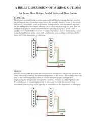
FRONT PANEL FEATURES<br />
POWER SWITCH (1)<br />
Depress the switch to the “on” position. The red LED will illuminate indicating power is being supplied to the<br />
unit.<br />
POWER LED (2)<br />
Illuminates when AC power is being supplied to the amp.<br />
T. DYNAMICS CONTROL (3)<br />
Adjusts the power level of the amplifier from 10% to 100% power. When set to lower settings, the power<br />
compression simulation will be much more pronounced.<br />
PRESENCE (4)<br />
An active tone control that boosts the extreme high frequencies by 6 dB.<br />
RESONANCE SWITCH (5)<br />
Used to fine-tune the low frequency range of the speaker enclosure by varying the damping factor of the<br />
amplifier between two presets.<br />
EFFECTS LEVEL SWITCH (6)<br />
Selects the effects loop operating level: -10 dBV (0.3 V RMS) when “out” and 0 dBV (1 V RMS) when “in.”<br />
EFFECTS RETURN (7)<br />
Input for returning signals from external low-level effects or signal processing equipment.<br />
3
EFFECTS SEND (8)<br />
Output for supplying signals to external low-level effects or signal processing equipment.<br />
REVERB LEVEL (9)<br />
Controls the overall reverb level.<br />
POST GAIN (10)<br />
Controls the overall volume level of the Lead channel. The final level adjustment should be made after the<br />
desired sound has been achieved.<br />
LOW, MID, & HIGH EQ (11,15)<br />
Passive tone controls that regulate the low, mid, and high frequencies for the Lead and Clean channels,<br />
respectively.<br />
GAIN SWITCH (12)<br />
Boosts the overall system gain. Depress to the “in” position to activate.<br />
THRASH SWITCH (13)<br />
Notches the mid range about 20 dB.<br />
PRE GAIN (14)<br />
Controls the input volume level of the Lead channel.<br />
CHANNEL SELECT SWITCH (16)<br />
Allows selection of the Lead or Clean channel. The “in” position of the switch selects the Lead channel and<br />
the “out” position selects Clean.<br />
NOTE: Channel selection may also be achieved by the remote footswitch. If remote selection is desired, the<br />
channel switch must be in the “in” (Lead) position.<br />
BRIGHT SWITCH (17)<br />
Provides a preset boost (6 dB) to treble frequencies. To activate, depress the switch to its “in” position.<br />
VOLUME (18)<br />
Controls the volume level of the Clean channel.<br />
LOW GAIN INPUT (19)<br />
Provided for instruments that have extremely high outputs, which can result in overdriving (distorting) the<br />
High Gain input. If both inputs are used simultaneously, the output levels are the same (both are low gain).<br />
HIGH GAIN INPUT (20)<br />
Used for most electric guitars. It is 6 dB louder than the Low Gain input.<br />
4
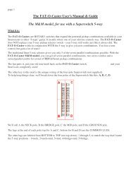
Back Panel:<br />
BACK PANEL FEATURES<br />
EXTERNAL SPEAKER JACKS (21)<br />
A<br />
Provided for connection of external speaker cabinet. Minimum external speaker impedance<br />
is 8 ohms (4 ohm total impedance).<br />
IMPEDANCE SELECTOR SWITCH (22)<br />
Used to select the appropriate impedance of the speaker enclosure(s). If two enclosures of equal impedance<br />
are used, the switch should be set at one half of that value (e.g., for two 16 ohm enclosures, set switch to<br />
8 ohms; for two 8 ohm enclosures, set switch to 4 ohms).<br />
PREAMP OUT (23)<br />
The preamp out can be used to route the amplified signal to a mixing console, tape recorder, etc. Connect<br />
the preamp output using a shielded cable to an input of the tape recorder, mixer, etc. This patch does not<br />
affect the operation of the amplifier.<br />
POWER AMP INPUT (24)<br />
Used to connect line level signal to the power amplifier.<br />
REMOTE SWITCH JACK (25)<br />
Provided for the connection of the supplied remote footswitch. The footswitch is used to select the Lead or<br />
Normal channels and defeat effects loop. When using remote footswitch, always insert the plug fully (second<br />
click) to insure proper operation.<br />
GROUND SWITCH (26)<br />
Three position rocker-type switch, which, in most applications, should be operated in its center or zero<br />
position. There may be some situations when audible hum and/or noise will come from the loudspeaker. If<br />
this situation arises, position the ground switch to either positive or negative (+or -) or until the noise is<br />
minimized.<br />
NOTE: Should the noise problem continue, consult your Authorized <strong>Peavey</strong> Dealer, the <strong>Peavey</strong> Factory, or a<br />
qualified service technician. THE GROUND SWITCH IS NOT FUNCTIONAL ON 220/240 VOLT MODELS.<br />
LINE CORD (120 V PRODUCTS ONLY) (27)<br />
For your safety, we have incorporated a three-wire line (mains) cable with proper grounding<br />
A<br />
facilities. It is not advisable to remove the ground pin under any circumstances. If it is necessary<br />
to use the equipment without proper grounding facilities, suitable grounding adaptors<br />
should be used. Less noise and greatly reduced shock hazard exists when the unit is operated<br />
with the proper grounded receptacles.<br />
5
SPECIFICATIONS<br />
Rated Power & Load:<br />
Power specs measured with<br />
T. Dynamics @ 10%<br />
100 W RMS into 16, 8, or<br />
4 ohms<br />
Power @ Clipping: (typically)<br />
(5% THD, 1 kHz, 120 V AC line)<br />
100 W RMS into 16, 8, or<br />
4 ohms<br />
Frequency Response:<br />
+O, 3 dB, 60 Hz to 20 kHz,<br />
@80WRMS<br />
Hum & Noise:<br />
Greater than 86 dB below rated<br />
power<br />
Power Consumption:<br />
Domestic: 300 W @ 60 Hz,<br />
120 VAC<br />
Export: 300 W @ 50/60 Hz,<br />
220-230/240 V AC<br />
PREAMP SECTION<br />
The following specs are measured @<br />
I kHz with the controls preset as follows:<br />
Push Bright, Off (out)<br />
Channel Select Normal (out)<br />
Low& High @ 10<br />
Mid 63 0<br />
Presence @ 0 dB<br />
Pre & Post Gain @ 10<br />
Gain & Thrash, Off (out)<br />
Normal Levels are with normal volume<br />
625<br />
Minimum Levels are with normal<br />
volume @ IO<br />
Preamp High Gain Input:<br />
Impedance: High-Z, 1 M ohm<br />
Nominal Input Level: -14 dBV,<br />
200 mV RMS<br />
Minimum Input Level: -24 dBV,<br />
60 mV RMS<br />
Maximum Input Level: 0 dBV,<br />
1 VRMS<br />
Preamp Low Gain Input:<br />
Impedance: High-Z, 44 K ohms<br />
Nominal Input Level: -8 dBV,<br />
400 mV RMS<br />
Minimum Input Level: -18 dBV,<br />
120 mV RMS<br />
Maximum Input Level: 6 dBV,<br />
2VRMS<br />
Effects Send:<br />
Load Impedance: 1 K ohm or<br />
greater<br />
Nominal Output Level: -10 dBV,<br />
0.3 V RMS or 0 dBV, 1 V RMS<br />
if Effects Level is in<br />
Effects Return:<br />
Impedance: High-Z, 22 K ohms<br />
Designed Input Level: -10 dBV,<br />
0.3 V RMS or 0 dBV, 1 V RMS<br />
if Effects Level is in<br />
(Switching jack provides Effects Send to<br />
Effects Return connection when not used)<br />
Preamp Output:<br />
Load Impedance: 1 K ohm or<br />
greater<br />
Nominal Output Level: 0 dBV,<br />
1 VRMS<br />
Power <strong>Amp</strong> Input:<br />
Impedance: High-Z, 30 K ohms<br />
Designed Input Level: 0 dBV,<br />
1 VRMS<br />
(Switching jack provides preamp output to<br />
power amp input connection when not<br />
used)<br />
System Hum & Noise @<br />
Nominal Input Level:<br />
(20 Hz to 20 kHz un weigh ted)<br />
72 dB below rated power<br />
Equalization:<br />
Special low, mid, & high passive<br />
type EQ<br />
Presence: +6 dB @ 5 kHz<br />
Push Bright: +6 dB @ 2 kHz<br />
Push Thrash: -20 dB notch @<br />
1 kHz in Lead channel<br />
Push Gain: Increases Lead gain<br />
Push Resonance: +6 dB @<br />
cabinet resonance<br />
External Footswitch Functions:<br />
Lead Channel Defeat (when<br />
selected with button)<br />
Effects Loop Bypass<br />
Dimensions & Weight:<br />
10.25” H x 24.375” W x 11.25” D<br />
35.7 Ibs.<br />
A<br />
Due to our eforts for constant improvements,<br />
features and specl$cations listed herein are subject to change without notice.
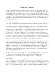
Flowchart<br />
HIGH GAIN<br />
AMP<br />
VOICING<br />
LEAD<br />
INPUT<br />
SWITCH<br />
LOGIC<br />
; ; ; y<br />
T<br />
EFX,<br />
0 *<br />
&%HBYpASS<br />
PUSH<br />
THRASH P 9<br />
I<br />
SEND<br />
x<br />
RETURN<br />
RESONANCE<br />
CLEAN<br />
SWITCH<br />
IMPEDANCE<br />
SWITCH<br />
T.DYNAMICS<br />
Tone Settings<br />
EFX<br />
POWER m, -- LOOP - HI~VI’RB ,.LAD Cl.liAN - INPU’IS -<br />
MEDIUM DISTORTION<br />
“OUT”<br />
JAZZ<br />
“OllT” AD.,I’Li, TO<br />
PREPLRtNCE
Consulte 10s diagramas de1 panel<br />
delantero en la seccih de ingl6s de este manual.<br />
Felicitaciones por la adquisicion del nuevo miembro de la serie TransTube@, el amplificador SupremeTM.<br />
Este novisimo amplificador representa aRos de investigation en el campo de la emulation del sonido<br />
generado por 10s tubos de vacio. El preamplificador ha sido redisenado utilizando una tecnologia en<br />
proceso de patentacion que redefine la distorsion similar a la creada por 10s tubos de vacio y la generation<br />
armonica en 10s amplificadores transistorizados.<br />
El nuevo circuit0 T. Dynamics, tambien en proceso de patentacion, crea el tan codiciado fenomeno de<br />
compresion de potencia que generaban 10s tubos de vacio. Esto, ademas del circuit0 de resonancia y<br />
presencia, produce la simulation de amplificador con tubos de vacio mas fiel que se haya logrado hasta la<br />
fecha. Ademas, se puede aumentar el efecto de compresion al bajar el control del circuit0 T. Dynamics, con<br />
lo cual se reduce el nivel de potencia que genera el amplificador.<br />
A fin de aumentar sun mas el rendimiento del amplificador Supreme, se utiliza un transformador adaptador<br />
de impedancias para producir una potencia de 100 watts en 16, 8 6 4 ohms; asimismo, un circuit0 de<br />
efectos controlable por conmutador de pedal le otorga mayor flexibilidad.<br />
POWER SWITCH (Interruptor de corriente) (1)<br />
Oprima el interruptor a la position “hacia dentro” (encendido). La luz roja del pilot0 (indicador) se encendera<br />
indicando que la unidad esta recibiendo corriente alterna.<br />
POWER LED (LED indicador de corriente) (2)<br />
Se ilumina cuando el amplificador recibe corriente alterna.<br />
T. DYNAMICS CONTROL (Control del circuit0 T. Dynamics) (3)<br />
Ajusta el nivel de potencia del amplificador de 10% a 100%. Cuando esta en la position mas baja, la<br />
simulation de compresion de potencia sera mas pronunciada.<br />
PRESENCE (Presencia) (4)<br />
Control de tono active que aumenta en 6 dB las frecuencias de 10s extermos agudos.<br />
RESONANCE SWITCH (Conmutador de resonancia) (5)<br />
Utilizado para realizar ajustes precisos del rango de frecuencias bajas de la caja de altavoces a traves de la<br />
variation del factor de amortiguacion de las frecuencias bajas del amplificador entre dos posiciones<br />
predeterminadas.<br />
EFFECTS LEVEL SWITCH (Conmutador de nivel de efectos) (6)<br />
Selecciona el nivel operational del circuit0 de efectos: -10 dBV (.3 V RMS) cuando esta “afuera” y a 0 dBV<br />
(1 V RMS) cuando esta “adentro”.<br />
EFFECTS RETURN (Retorno de efectos) (7)<br />
Entrada para el retorno de setiales procedentes de equipos de efectos externos de bajo nivel o de<br />
procesadores de serial.<br />
EFFECTS SEND (Envio de efectos) (8)<br />
Salida para proporcionar sefiales a efectos exteriores de bajo nivel o a equipos procesadores de serial.<br />
8
REVERB LEVEL (Nivel de reverberation) (9)<br />
Controla el nivel global de la reverberation.<br />
POST GAIN (Control de ganancia posterior del preamplificador) (10)<br />
Controla el volumen general del canal solista. El ajuste final de nivel debe hacerse despues de que se haya<br />
obtenido el sonido deseado.<br />
LOW, MID, & HIGH EQ (Ecualizador de frecuencias graves, medias, y agudas) (11,15)<br />
Controles de tono pasivo que regulan las frecuencias graves, medias, y agudas del canal “lead” (solista) o<br />
“clean”, respectivamente.<br />
GAIN SWITCH (Interruptor de ganancia) (12)<br />
Proporciona impulso a la ganancia general del sistema. Para activarlo oprimalo a la position “in” (hacia<br />
adentro).<br />
THRASH (Conmutador de batido) (13)<br />
Recorta la escala media en casi 20 dB.<br />
PRE GAIN (Control del preamplificador) (14)<br />
Controla la entrada de volumen del canal solista.<br />
CHANNEL SELECT SWITCH (Interruptor para seleccih del canal) (16)<br />
Permite la selection del canal “lead” (solista) o “clean.” La position hacia dentro selecciona el canal “lead” y<br />
la position hacia fuera selecciona el canal “clean”.<br />
NOTA: Tambien se puede lograr la selection del canal por medio del pedal interruptor remoto. Si desea la<br />
seleccicn a control remoto, el interruptor de canal debe estar en la position “in” (hacia adentro) (canal de<br />
solista).<br />
BRIGHT SWITCH (Interruptor de brillo) (17)<br />
Proporciona un impulso preajustado de +6 dB a las frecuencias agudas. Para activarlo, empuje el<br />
interruptor a la position “hacia dentro”.<br />
VOLUME (El volumen) (18)<br />
Controla el nivel de volumen del canal “clean”.<br />
LOW GAIN INPUT (Entrada de baja ganancia) (19)<br />
Se suministra para instrumentos que tienen una salida extremadamente alta, la cual puede causar la<br />
sobrecarga (distorsion) de la entrada de alta ganancia. Si se usan ambas entradas simultaneamente, el<br />
nivel de salida es el mismo (ambos son de baja ganancia).<br />
HIGH GAIN INPUT (Entrada de ganancia alta) (20)<br />
Se usa para la mayoria de las guitarras electricas. Tiene 6 dB mas volumen que la entrada de baja<br />
ganancia.<br />
9
Tablero Trasero:<br />
EXTERNAL SPEAKER JACKS (Enchufes hembra de altavoz externo) (21)<br />
A<br />
Se suministra para la conexion de bafles externos. La impedancia minima del altavoz<br />
externo es de 8 ohms (4 ohms de impedancia total).<br />
IMPEDANCE SELECTOR SWITCH (Interruptor del selector de impedancia) (22)<br />
Se usa para seleccionar la impedancia adecuada para la(s) caja(s) de altavoces. Si se usan dos cajas de<br />
impedancia equivalente, el selector debera sintonizarse en la mitad de dicho valor (por ejemplo, para dos<br />
cajas de 16 ohms, hay que sintonizarlo en 8 ohms; para dos cajas de 8 ohms, hay que sintonizarlo en<br />
4 ohms).<br />
PREAMP OUT (Salida de preamplificador) (23)<br />
La salida del preamplificador puede usarse para mandar la senal a una consola de mezcla, grabadora, etc.<br />
Conecte la salida del preamplificador, utilizando un cable blindado, a una entrada de la grabadora,<br />
mezclador, etc. Esta interconexion no afecta la operation del amplificador.<br />
POWER AMP INPUT (Entrada del amplificador de potencia) (24)<br />
Se usa para conectar la senal del nivel de linea al amplificador de potencia.<br />
REMOTE SWITCH JACK (Enchufe hembra de interruptor remoto) (25)<br />
Se suministra para la conexion del pedal interruptor de control remoto que se suministra. El pedal<br />
interruptor se utiliza para seleccionar 10s canales solista o normal y desactivar el lazo de efectos. Cuando se<br />
utilice el pedal de control remoto, inserte siempre la clavija completamente (Segundo ret&-r) para asegurar el<br />
correct0 funcionamiento.<br />
LINE CORD (120 V products only) (Cable de corriente para 120 v solamente) (26)<br />
A<br />
Para su protection hemos incorporado un cable de 3 polos con polo a tierra. No es<br />
recomendable remover la pata del polo a tierra bajo ninguna circunstancia, se recomienda<br />
un adaptador en case necesario. Esto reducira ruidos y peligrosos corrientazos.<br />
10
Veuillez vous r6f6rer au “front panel line art”<br />
situ6 dans la section en langue anglaise de ce manuel.<br />
Felicitations pour votre achat du Supreme TM TransTube@ nouvelle serie. Cet amplificateur, entierement<br />
novateur, est le fruit d’annees de recherche sur I’emulation de tube a vide. La nouvelle conception du<br />
preamplificateur s’appuie sur une technologie (brevet en instance) qui redefinit la distorsion de type tube et<br />
la g&-&ration d’harmoniques dans les amplificateurs a transistor.<br />
Le nouveau circuit de ((Dynamique T>> (brevets egalement en instance) tree le phenomene si longtemps<br />
recherche de compression de la puissance de tube. S’alliant aux circuits de resonance et de presence, il<br />
donne la meilleure simulation d’amplificateur a tube a ce jour. Cet effet de compression est augmente en<br />
diminuant la commande ((Dynamique Tj>, ce qui se traduit par une baisse du niveau de puissance emise par<br />
I’amplificateur.<br />
Afin d’ameliorer les performances de I’amplificateur Supreme, un transformateur d’adaptation des<br />
impedances livre 100 watts en 16, 8 ou 4 ohms. Une boucle d’effets actionnee par pedale de commande a<br />
distance permet de surcroit une plus grande souplesse d’utilisation.<br />
POWER SWITCH (Interrupteur d’alimentation) (1)<br />
Mettre I’interrupteur en position “On”. La lampe temoin rouge (DEL) s’illumine indiquant que I’appareil est<br />
alimente en courant.<br />
POWER LED (DEL tkmoin de mise sous tension) (2)<br />
S’allume lorsque I’ampli recoit I’alimentation CA.<br />
T. DYNAMICS CONTROL (Commande CcDynamique Tjb) (3)<br />
Regle le niveau de puissance de I’amplificateur de 10 a 100%. Lorsqu’il est regle en bas de plage, la simulation<br />
de compression de puissance est bien plus prononcee.<br />
PRESENCE (Prhence) (4)<br />
Reglage de tonalite actif qui renforce les frequences extremes aigues (+6 dB).<br />
RESONANCE SWITCH (Commutateur de rbonance) (5)<br />
Utilise pour assurer I’accord precis de la gamme des basses frequences de I’enceinte du haut-parleur en<br />
faisant varier le facteur d’amot-tissement de I’amplificateur entre deux reglages predetermines.<br />
EFFECTS LEVEL SWITCH (Commutateur de niveau d’effets) (6)<br />
Selectionne le niveau de fonctionnement de la boucle d’effets : -10 dBV (0,3 V RMS) en et 0 dBV<br />
(1 V RMS) en .<br />
EFFECTS RETURN (Retour d’effets) (7)<br />
Prise d’entree pour signaux provenant d’appareils externes de traitement de signal ou d’effets a bas niveau.<br />
EFFECTS SEND (Envoi d’effets) (8)<br />
Prise de sortie servant a fournir des signaux a des appareils externes de traitement de signal ou d’effets a<br />
bas niveau.<br />
11
REVERB LEVEL (Niveau de reverberation) (9)<br />
Controle le niveau de reverberation global.<br />
POST GAIN (10)<br />
Commande le volume general du canal “Lead”. Le reglage final de niveau doit etre effectue apres avoir<br />
obtenu la sonorite dosiree a I’aide des autres reglages.<br />
LOW, MID, & HIGH EQ (egalisation graves, moyennes et aigu&) (11, 15)<br />
Reglages de tonalite passifs reglant respectivement les frequences graves, moyennes et aigues pour les<br />
canaux “Lead” ou “Clean”.<br />
GAIN SWITCH (Interrupteur de gain) (12)<br />
Hausse le gain global du systeme. Abaisser a la position “In” pour activer.<br />
THRASH SWITCH (Commutateur anti-emballement) (13)<br />
Ajuste le registre moyen d’environ 20 dB.<br />
PRE GAIN (14)<br />
Controle le niveau de volume a I’entree sur du canal “Lead”.<br />
CHANNEL SELECT SWITCH (Selecteur de canal) (16)<br />
Permet de selectionner les canaux “Lead” ou “Clean”. La position “In” du selecteur correspond au canal<br />
“Lead”. La position “Out” selectionne le canal “Clean”.<br />
NOTE: La selection de canal peut aussi s’accomplir a distance a I’aide de la pedale-interrupteur. Pour que la<br />
selection a distance soit possible, le canal doit etre en position “In” (“Lead”).<br />
BRIGHT SWITCH (Selecteur de brillance) (17)<br />
Accentue (6 dB) les frequences aigues. Pour activer, mettre le bouton en position “In”.<br />
VOLUME (18)<br />
Controle le niveau de volume du canal “Clean”.<br />
LOW GAIN INPUT (Entree faible gain) (19)<br />
Cette prise accepte les instruments a tres haut niveau de sortie qui causeraient de la saturation (distorsion)<br />
sur I’entree “High Gain”. Si les deux entrees sont utilisees simultanhment, les niveaux sont alors equivalents<br />
(“Low Gain”).<br />
HIGH GAIN INPUT (Entree haut gain) (20)<br />
Cette prise s’utilise avec la plupart des guitares electriques. Elle donne un gain superieur de 6 dB a I’entree<br />
“1 -ow Gain”.<br />
12
Panneau Arriere:<br />
EXTERNAL SPEAKER JACKS (Prises pour haut-parleur externe) (21)<br />
A<br />
Sortie pour branchement d’une enceinte de haut-parleur separee. Impedance de hautparleur<br />
externe minimale : 8 ohms (impedance totale de 4 ohms).<br />
IMPEDANCE SELECTOR SWITCH (Interrupteur de selection d’impedance) (22)<br />
Sert a selectionner I’impedance appropriee pour la ou les enceintes de<br />
haut-parleurs. Lorsque deux enceintes de meme impedance sont utilisees, mettre I’interrupteur sur la moitie<br />
de cette valeur (pour 2 enceintes de 16 ohms, mettre I’interrupteur sur 8 ohms, pour deux enceintes de<br />
8 ohms, le mettre sur 4 ohms).<br />
PREAMP OUT (Sortie preampli) (23)<br />
La sortie preampli peut etre utilisee pour amener le signal a une table de mixage, un magnetophone, etc.<br />
Utilisez des cables blind& pour brancher la sortie du preampli a I’entree d’un magnetophone, d’un<br />
melangeur, etc. Ce branchement n’affecte pas le fonctionnement de I’amplificateur.<br />
POWER AMP INPUT (Entree ampli de puissance) (24)<br />
Sert a brancher un signal de niveau ligne a I’amplificateur de puissance.<br />
REMOTE SWITCH JACK (Prise pour interrupteur a distance) (25)<br />
Permet de brancher la pedale-interrupteur incluse. L’interrupteur au pied est utilise pour selectionner les<br />
canaux “Normal” ou “Lead” et pour mettre hors circuit la boucle d’effets. Afin d’assurer un bon<br />
fonctionnement lors de I’utilisation de I’interrupteur au pied, inserez la fiche bien a fond (au second clic).<br />
LINE CORD (120 V products only) (Cordon d’alimentation pour appareils 120 V seulement) (26)<br />
Pour votre securite, nous avons incorpore un cable d’alimentation secteur a 3 fils avec mise-<br />
A<br />
a-terre appropriee. II nest pas recommande d’enlever la broche de mise-a-terre en aucune<br />
circonstance. S’il est necessaire d’utiliser I’equipement sans mise-a-terre appropriee, utilisez<br />
des adaptateurs de mise-a-terre convenables. Une bonne mise-a-terre amoindrit le bruit de<br />
fond et reduit grandement les risques de choc.<br />
13
Siehe Diagramm der Frontplatte im englischen Teil des Handbuchs.<br />
Wir begluckwunschen Sie zum Erwerb dieses Verstarkers aus der neuen SupremeTM Serie. Der neue<br />
Supreme ist das Ergebnis langjahriger Forschungsarbeit auf dem Gebiet der Hochvakuumrohrenemulation.<br />
Dieser Vorverstarker wurde unter Zuhilfenahme einer zum Patent angemeldeten Technologie konstruiert, die<br />
rohrenahnliche Verzerrung und Oberwellenerzeugung in Festkorperversttirkern neu definiert.<br />
Der neue T.-Dynamik-Schaltungsaufbau - der such fur mehrere Patente angemeldet wurde - erzeugt das<br />
fur Rdhren typische Hochleistungskompressionsphanomen, nach dem bisher vergeblich gesucht wurde.<br />
Dazu kommt der Resonanz- und Prasenzschaltungsaufbau und das Ergebnis ist die wohl gelungenste<br />
Rohrenverstarkersimulation, die man sich vorstellen kann. Der Kompressionseffekt wird verstarkt, wenn Sie<br />
die T.-Dynamik herunterregeln und somit den Ausgabepegel das Verstarkers vermindern.<br />
Urn die Leistung das Supreme noch zu erhdhen, vet-fijgt dieser ijber einen Impedanz-<br />
Anpassungstransformator, der 100 Watt an 16, 8 oder 4 Ohm liefert. Eine ijber FuOschalter ein-/<br />
ausschaltbare Effektschleife ermdglicht mehr Flexibilitat.<br />
POWER SWITCH (Netzschalter) (1)<br />
Bringen Sie den Schalter auf die ON-Position. Die rote Kontrollampe (LED) leuchtet und zeigt an, da8 das<br />
Gerat eingeschaltet ist.<br />
POWER LED (Kontrollampe) (2)<br />
Zeigt die eingeschaltete Netzspannung an.<br />
T. DYNAMICS CONTROL (T.-Dynamikregler) (3)<br />
Regelt den Leistungspegel das Verst&kers von 10% bis 100% Leistung. Bei den niedrigeren Einstellungen<br />
ist die Simulation der Leistungskompression sehr viel betonter.<br />
PRESENCE (Anwesenheit) (4)<br />
Eine aktive Tonkontrolle, welche die extrem hohen Frequenzen urn 6 dB boostet (anhebt).<br />
RESONANCE SWITCH (Resonanzschalter) (5)<br />
Damit wird der tiefe Frequenzbereich das Lautsprechergehauses feinabgestimmt, indem der<br />
Dampfungsfaktor das Verstarkers zwischen zwei Vorgaben variiert wird.<br />
EFFECTS LEVEL SWITCH (EFfects-pegelschalter) (6)<br />
Wahlt den Operationsbereich der Effektschleife aus: -10 dBV (0,3 V RMS), wenn der Schalter in der “out”-<br />
Position steht und 0 dBV (1 V RMS), wenn in der “in’‘-Position.<br />
EFFECTS RETURN (Effekteingang) (7)<br />
Eingang fur ruckfuhrende Signale von niederohmigen Effekten oder Signal-Prozessoren.<br />
EFFECTS SEND (Effektausgang) (8)<br />
Ausgang fur Zuliefersignale zu externen niederohmigen Effekten oder Signal-Prozessoren.<br />
REVERB LEVEL (Reverb-pegel) (9)<br />
Regelt den Reverb-Pegel.<br />
14
POST GAIN (10)<br />
Regelt die Gesamtlautstarke das “Lead”-Kanal. Die endgiiltige Lautstarkeeinstellung sollte erst dann<br />
vorgenommen werden, wenn der gewunschte Klang erreicht ist.<br />
LOW, MID, & HIGH EQ (Tiefen, Mittleren und htihen-equalizerregler) (11,15)<br />
Hierbei handelt es sich urn passive Klangregler, die tiefe, mittlere und hohe Frequenzen entsprechend<br />
regeln fur das “Lead”- und “Clean”-Kanals.<br />
GAIN SWITCH (12)<br />
Boostet die Gesamtlautstarke. Zum Einschalten auf die “In” - Position bringen.<br />
THRASH SWITCH (Thrash schalter) (13)<br />
Andert den Mittelbereich urn etwa 20 dB.<br />
PRE GAIN (14)<br />
Kontrolliert den Vorstufenpegel das Lead-Kanal.<br />
CHANNEL SELECT SWITCH (Kanal auswtihlenschalter) (16)<br />
Erlaubt die Auswahl das “Lead”- oder das “Clean”-Kanal. Die “W-Position das Schalters wahlt den “Lead”-<br />
Kanal, die “Out’‘-Position den “Clean”-Kanal an.<br />
MERKE: Kanalwahl kann such mittels dem FernbedienungsfuOschalter ausgeftihrt werden. Dazu mul3 der<br />
“Channel”-Schalter sich in der “in” (Lead) Position befinden.<br />
BRIGHT SWITCH (17)<br />
Besorgt einen voreingestellten Schub (+6 dB) in den hohen Frequenzen. Zur Aktivierung den Knoph in die<br />
“W-Position drucken.<br />
VOLUME (18)<br />
Regelt den Pegel das “Clean”-Kanal.<br />
LOW GAIN INPUT (Tiefen gain-eingang) (19)<br />
Dieser Eingang ist fur die lnstrumente vorgesehen, die ein besonders hohes Ausgangssignal erzeugen.<br />
Falls beide Eingange gleichzeitig benutzt werden, sind die Ausgangssignale gleich (beide sind dann Low<br />
Gain).<br />
HIGH GAIN INPUT (H6hen gain-Eingsng) (20)<br />
Dieser Eingang kann fur die meisten elektrischen Gitarren verwendet werden. Er ist 6 dB empfindlicher als<br />
der Low Gain Input.<br />
15
Riickplatte:<br />
0 26<br />
EXTERNAL SPEAKER JACKS (Buchsen fur externe lautsprecher) (21)<br />
A<br />
AnschluObuchse fur einen zusatzlichen Lautsprecher. Die Mindestimpedanz fur externe<br />
Lautsprecher betragt 8 Ohm (4 Ohm Gesamtimpedanz).<br />
IMPEDANCE SELECTOR SWITCH (Impedanz-Wahlschalter) (22)<br />
Dient zur Wahl der passenden lmpedanz fur den oder die Lautsprecher. Wenn zwei Lautsprecherboxen<br />
gleicher Impedanz eingesetzt werden, muf3 der Schalter auf den halben Wert eingestellt werden (d.h. ftir<br />
zwei 16-Ohm-Boxen auf 8 Ohm oder fur zwei 8-Ohm-Boxen auf 4 Ohm).<br />
PREAMP OUT (Vorstufenausgang) (23)<br />
Dieser Ausgang kann zum AnschluO das Verst&kers an einen Mixer, eine Bandmaschine, etc. verwendet<br />
werden. Verbinden Sie den Ausgang mit Hilfe eines abgeschirmten Kabels mit dem Eingang das<br />
entsprechenden Gerates. Dieser Anschluf3 beeinflu(3t die Funktionen das Verstarkers nicht.<br />
POWER AMP INPUT (Leistungsverstarkereingang) (24)<br />
Vorgesehen fur den AnschluO eines Line-Signals an den Endverstarker.<br />
REMOTE SWITCH JACK (Buchsen fur fern ful3schalter) (25)<br />
Sorgt fur die Verbindung das mitgelieferten Fernbedienungs-FuOschalters. Der FuOschalter wird verwendet,<br />
urn zwischen den beiden Eingangskanalen zu wahlen und urn den Effektweg zu schalten. Beim AnschluB<br />
das FuOschalters muf3 der Stecker vollig eingesteckt sein (zweimal Klicken), urn die richtige Funktion zu<br />
gewahrleisten.<br />
LINE CORD (120 V products only) (Nur bei 120 Volt-Geraten) (26)<br />
Zu lhrer Sicherheit haben wir das Gerat mit einem dreiadrigen geerdeten Netzkabel<br />
A<br />
versehen. Es ist unter keinen Umstanden empfehlenswert den Erdungskontakt das<br />
AnschluOkabels zu Ibsen. Falls es notwendig sein sollte, das Equipment ohne die<br />
vorgesehene Erdung zu betreiben empfiehlt sich die Verwendung eines Grounding Adaptors.<br />
Die geringsten Stbrger&rsche und die hochste Sicherheit vor elektrischen Schlagen wird<br />
jedoch durch die Benutzung der vorgesehenen Erdungsmdglichkeiten erreicht.<br />
16
For further information on other <strong>Peavey</strong> products,<br />
ask your Authorized <strong>Peavey</strong> Dealer for the<br />
appropriate <strong>Peavey</strong> catalog/publication:<br />
A0<br />
Bass Guitars<br />
Guitars<br />
Bass <strong>Amp</strong>lification<br />
Guitar <strong>Amp</strong>lification<br />
Sound Reinforcement Enclosures<br />
Microphones<br />
Keyboards<br />
DJ<br />
Lighting<br />
Mixers, Powered/Non-Powered<br />
Accessories/Cables<br />
Effects Processors<br />
Axcess’” Wear<br />
The <strong>Peavey</strong> Beat’”<br />
Monitor@ Magazine<br />
Key Issues’”<br />
Low Down’”<br />
PM’” Magazine<br />
17
THIS LIMITED WARRANTY VALID ONLY WHEN PURCHASED AND REGISTERED IN THE UNITED STATES OR CANADA. ALL EXPORTED PRODUCTS<br />
ARE SUBJECT TO WARRANTY AND SERVICES TO BE SPECIFIED AND PROVIDED BY THE AUTHORIZED DISTRIBUTOR FOR EACH COUNTRY.<br />
Ces clauses de garantie ne sont vaiables qu’aux Etats-Unis et au Canada. Dans tour les autres pays, les clauses de garantie et de maintenance sont<br />
fixees par le distributeur national et assuree par lul seion la legislation envigueur. • • Diese Garantie ist nur in den USA and Kanada gultig. Alle Export-<br />
Produkte sind der Garantie und dem Service des lmporteurs des jewelligen Landes unterworfen. • • Esta garantia es valida solamente cuando el<br />
product0 es comprado en E.U. continentales o en Canada. Todos 10s productos que Sean comprados en el extranjero, estan sujetos a las garantias y<br />
servicio que cada distribuidor autorizado determine y ofrezca en 10s diferentes paises.<br />
PEAVEY ONE-YEAR LIMITED<br />
WARRANTY/REMEDY<br />
PEAVEY ELECTRONICS CORPORATION (“PEAVEY”) warrants this product, EXCEPT for covers, footswitches, patchcords, tubes and meters, to be free from<br />
defects in material and workmanship for a period of one (1) year from date of purchase, PROVIDED, however, that this limited warranty is extended only to the<br />
original purchaser subject conditions, exclusions, and limitations hereinafter set forth:<br />
PEAVEY 90-DAY LIMITED WARRANTY ON TUBES AND METERS<br />
If this product contains tubes or meters, <strong>Peavey</strong> warrants the tubes or meters contained in the product to be free from defects in material and workmanship for<br />
a period of ninety (90) days from date of purchase; PROVIDED, however, that this limited warranty is extended only to the original retail purchaser and is also<br />
subiect to the conditions, exclusions, and lrmitations hereinafter set forth.<br />
CONDITIONS, EXCLUSIONS, AND LIMITATIONS OF LIMITED WARRANTIES<br />
These limited warranties shall be void and of no effect, if:<br />
a. The first purchase of the product is for the purpose of resale; or<br />
b. The original retail purchase is not made from an AUTHORIZED PEAVEY DEALER; or<br />
c. The product has been damaged by accident or unreasonable use, neglect, improper service or maintenance, or other causes not arising out of defects in<br />
material or workmanshrp; or<br />
d. The serial number affixed to the product is altered, defaced, or removed.<br />
In the event of a defect in material and/or workmanship covered by this limited warranty, <strong>Peavey</strong> will:<br />
a. In the case of tubes or meters, replace the defective component without charge.<br />
b. In other covered cases (i.e., cases involving anything other than covers, footswitches, patchcords, tubes or meters), repair the defect in material or<br />
workmanship or replace the product, at <strong>Peavey</strong>’s option; and provided,<br />
that, in any case, all costs of shipprng, necessary, are paid by you, the<br />
purchaser.<br />
THE WARRANTY REGISTRATION CARD SHOULD BE ACCURATELY COMPLETED AND MAILED TO AND RECEIVED BY PEAVEY WITHIN FOURTEEN (14)<br />
DAYS FROM THE DATE OF YOUR PURCHASE.<br />
In order to obtain service under these warranties, you must:<br />
Bring the defective item to any PEAVEY AUTHORIZED DEALER or AUTHORIZED PEAVEY SERVICE CENTER and present therewith the ORIGINAL<br />
PROOF OF PURCHASE supplied to you by the AUTHORIZED PEAVEY DEALER in connection with your purchase from him of this product.<br />
If the DEALER or SERVICE CENTER is unable to provide the necessary warranty service you will be directed to the nearest other PEAVEY AUTHORIZED<br />
DEALER or AUTHORIZED PEAVEY SERVICE CENTER which can provide such service.<br />
OR<br />
Ship the defective item, prepaid, to:<br />
PEAVEY ELECTRONICS CORPORATION<br />
International Service Center<br />
326 Hwy. 11 & 80 East<br />
Meridian, MS 39301<br />
Including therewith a complete, detailed description of the problem, together with a legible copy of the original PROOF OF PURCHASE and a complete return<br />
address. Upon <strong>Peavey</strong>’s receipt of these items: If the defect is remedial under these limited warranties and the other terms and conditions expressed herein<br />
have been complied with, <strong>Peavey</strong> will provide the necessary warranty service to repair or replace the product and will return it, FREIGHT COLLECT, to you,<br />
the purchaser.<br />
<strong>Peavey</strong>’s liability to the purchaser for damages from any cause whatsoever and regardless of the form of action, Including negligence, is limited to the actual<br />
damages up to the greater of $500.00 or an amount equal to the purchase price of the product that caused the damage or that is the subject of or is directly related<br />
to the cause of action. Such purchase price will be that in effect for the specific product when the cause of action arose. This limitation of liabilrty will not apply to<br />
claims for personal injury or damage to real property or tangible personal property allegedly caused by <strong>Peavey</strong>’s negligence. <strong>Peavey</strong> does not assume liabrlrty for<br />
personal injury or property damage arising out of or caused by a non-<strong>Peavey</strong> alteration or attachment, nor does <strong>Peavey</strong> assume any responsibility for damage to<br />
interconnected non-<strong>Peavey</strong> equipment that may result from the normal functioning and maintenance of the <strong>Peavey</strong> equipment.<br />
UNDER NO CIRCUMSTANCES WlLL PEAVEY BE LIABLE FOR ANY LOST PROFITS, LOST SAVINGS ANY INCIDENTAL DAMAGES. OR ANY<br />
CONSEQUENTIAL DAMAGES ARISING OUT OF THE USE OR INABILITY TO USE THE PRODUCT, EVEN IF PEAVEY HAS BEEN ADVISED OF THE<br />
POSSIBILITY OF SUCH DAMAGES.<br />
THESE LIMITED WARRANTIES ARE IN LIEU OF ANY AND ALL WARRANTIES. EXPRESSED OR IMPLIED. INCLUDING. BUT NOT LIMITED TO. THE<br />
IMPLIED WARRANTIES OF MERCHANTABILITY AND FITNESS FOR A PARTICULAR USE; PROVIDED, HOWEVER, THAT iF THE OTHER TERMS’AND<br />
CONDITIONS NECESSARY TO THE EXISTENCE OF THE EXPRESSED, LIMITEG WARRANTIES, AS HEREINABOVE STATED, HAVE BEEN COMPLIED<br />
WITH, IMPLIED WARRANTIES ARE NOT DISCLAIMED DURING THE APPLICABLE ONE-YEAR OR NINETY-DAY PERIOD FROM DATE OF PURCHASE OF<br />
THIS PRODUCT.<br />
SOME STATES DO NOT ALLOW LIMITATION ON HOW LONG AN IMPLIED WARRANTY LASTS, OR THE EXCLUSION OR LIMITATION OF INCIDENTAL<br />
OR CONSEQUENTIAL DAMAGES, SO THE ABOVE LIMITATIONS OR EXCLUSIONS MAY NOT APPLY TO YOU. THESE LIMITED WARRANTIES GIVE YOU<br />
SPECIFIC LEGAL RIGHTS, AND YOU MAY ALSO HAVE OTHER RIGHTS WHICH MAY VARY FROM STATE TO STATE.<br />
THESE LIMITED WARRANTIES ARE THE ONLY EXPRESSED WARRANTIES ON THIS PRODUCT, AND NO OTHER STATEMENT, REPRESENTATION,<br />
WARRANTY, OR AGREEMENT BY ANY PERSON SHALL BE VALID OR BINDING UPON PEAVEY.<br />
In the event of any modification or disclaimer of expressed or implied warranties, or any limitation of remedies, contained herein conflicts with applicable law,<br />
then such modification, disclaimer or limitation, as the case may be, shall be deemed to be modified to the extent necessary to comply with such law.<br />
Your remedies for breach of these warranties are limited to those remedies provided herein and <strong>Peavey</strong> Electronics Corporation gives this limited warranty only<br />
with respect to equipment purchased in the United States of America.<br />
INSTRUCTIONS - WARRANTY REGISTRATION CARD<br />
I. Mail the completed WARRANTY REGISTRATION CARD to:<br />
PEAVEY ELECTRONICS CORPORATION<br />
P.O. BOX 2898<br />
Meridian, MS 39302-2898<br />
a. Keep the PROOF OF PURCHASE. In the event warranty service is required during the warranty period, you will need this document. There will be no<br />
identification card issued by <strong>Peavey</strong> Electronics Corporation.<br />
2. IMPORTANCE OF WARRANTY REGISTRATION CARDS AND NOTIFICATION OF CHANGES OF ADDRESSES:<br />
a. Completion and mailing of WARRANTY REGISTRATION CARDS - Should notification become necessary for any condition that may require correction,<br />
the REGISTRATION CARD will help ensure that you are contacted and properly notified.<br />
b. Notice of address changes - If you move from the address shown on the WARRANTY REGISTRATION CARD, you should notify <strong>Peavey</strong> of the change of<br />
address so as to facilitate your receipt of any bulletins or other forms of notification which may become necessary in connection with any condition that may<br />
require disseminatron of information or correction.<br />
3. You may contact <strong>Peavey</strong> directly by telephoning (601) 483-5365.<br />
18
IMPORTANT SAFETY INSTRUCTIONS<br />
WARNING: When using electric products, basic cautions should always be followed, including the following.<br />
1. Read all safety and operating instructions before using this product.<br />
2. All safety and operating instructions should be retained for future reference.<br />
3. Obey all cautions in the operating instructions and on the back of the unit.<br />
4. All operating instructions should be followed.<br />
5.<br />
6.<br />
7.<br />
8.<br />
9.<br />
10.<br />
11.<br />
12.<br />
13.<br />
14.<br />
15.<br />
16.<br />
17.<br />
18.<br />
This product should not be used near water, i.e., a bathtub, sink, swimming pool, wet basement, etc.<br />
This product should be located so that its position does not interfere with its proper ventilation. It should not be placed l-Tat against a<br />
wall or placed in a built-in enclosure that will impede the flow of cooling air.<br />
This product should not be placed near a source of heat such as a stove, radiator, or another heat producing amplifier.<br />
Connect only to a power supply of the type marked on the unit adjacent to the power supply cord.<br />
Never break off the ground pin on the power supply cord. For more information on grounding, write for our free booklet “Shock<br />
Hazard and Grounding.”<br />
Power supply cords should always be handled carefully. Never walk or place equipment on power supply cords. Periodically check<br />
cords for cuts or signs of stress, especially at the plug and the point where the cord exits the unit.<br />
The power supply cord should be unplugged when the unit is to be unused for long periods of time.<br />
If this product is to be mounted in an equipment rack, rear support should be provided.<br />
Metal parts can be cleaned with a damp rag. The vinyl covering used on some units can be cleaned with a damp rag or an ammoniabased<br />
household cleaner if necessary. Disconnect unit from power supply before cleaning.<br />
Care should be taken so that objects do not fall and liquids are not spilled into the unit through the ventilation holes or any other<br />
openings.<br />
This unit should be checked by a qualified service technician if:<br />
a. The power supply cord or plug has been damaged.<br />
b. Anything has fallen or been spilled into the unit.<br />
c. The unit does not operate correctly.<br />
d. The unit has been dropped or the enclosure damaged.<br />
The user should not attempt to service this equipment. All service work should be done by a qualified service technician.<br />
This product should be used only with a cart or stand that is recommended by <strong>Peavey</strong> Electronics.<br />
Exposure to extremely high noise levels may cause a permanent hearing loss. Individuals vary considerably in susceptibility to noise<br />
induced hearing loss, but nearly everyone will lose some hearing if exposed to sufficiently intense noise for a sufficient time.<br />
The U.S. Government’s Occupational Safety and Health Administration (OSHA) has specified the following permissible noise level<br />
exposures.<br />
Duration Per Day In Hours<br />
Sound Level dBA, Slow Response<br />
8 90<br />
6 92<br />
4 95<br />
3 97<br />
2 100<br />
1 l/2 102<br />
1 105<br />
l/2 110<br />
l/4 or less 115<br />
According to OSHA. any exposure in excess of the above permissible limits could result in some hearing loss.<br />
Ear plugs or protectors in the ear canal{ or over the ears must be worn when operating this amplification system in order to prevent a<br />
permanent hearing lo\x if exposure i\ in escec\ of the limits as set forth above. To ensure against potentially dangerous exposure to high<br />
sound pressure levels, it is recommended that all persons exposed to equipment capable of producing high sound pressure levels such as<br />
this amplification system be protected by hearing protectors while this unit is in operation.<br />
SAVE THESE INSTRUCTIONS!<br />
19
Features and specifications subject to change without notice.<br />
<strong>Peavey</strong> Electronics Corporation 711 A Street / Meridian, MS 39301 / U.S.A. / (601) 483-5365 / Fax 486-1278<br />
01996 #I80300272 Printed in U.S.A. l/96