A Simulator for the MARIE Architecture - Penn State Harrisburg Math ...
A Simulator for the MARIE Architecture - Penn State Harrisburg Math ...
A Simulator for the MARIE Architecture - Penn State Harrisburg Math ...

Create successful ePaper yourself
Turn your PDF publications into a flip-book with our unique Google optimized e-Paper software.
The <strong>Penn</strong>sylvania <strong>State</strong> University<br />
The Graduate School<br />
Capital College<br />
MarieSim: A <strong>Simulator</strong> <strong>for</strong> <strong>the</strong> <strong>MARIE</strong><br />
<strong>Architecture</strong><br />
A Master’s Paper in<br />
Computer Science<br />
By<br />
Julia M. Lobur<br />
© 2003 Julia M. Lobur<br />
Submitted in Partial Fulfillment<br />
of <strong>the</strong> Requirements<br />
<strong>for</strong> <strong>the</strong> Degree of<br />
Master of Science<br />
April 4, 2003
Abstract<br />
The purpose of this project is to provide computer architecture students with an<br />
interactive simulator to deepen <strong>the</strong>ir understanding of <strong>the</strong> workings of a simple computer,<br />
<strong>MARIE</strong>, which is an acronym <strong>for</strong> a Machine <strong>Architecture</strong> that is Really Intuitive and<br />
Easy. The simulator environment, MarieSim, presents this machine architecture in a<br />
detailed, yet visually attractive manner. Through interaction with its graphical<br />
environment, students can observe how assembly language statements affect <strong>the</strong> registers<br />
and memory of a computer system. The graphical environment <strong>for</strong> MarieSim is written<br />
in Java Swing. The integrated <strong>MARIE</strong> assembler is written in Java.<br />
ii
Table of Contents<br />
Abstract ........................................................................................................................... ii<br />
Acknowledgements............................................................................................................ iv<br />
List of Figures..................................................................................................................... v<br />
1 Introduction................................................................................................................. 1<br />
2 A Simple Machine <strong>Architecture</strong> ............................................................................... 10<br />
2.1 Registers and Buses.......................................................................................... 10<br />
2.2 The Data Path................................................................................................... 11<br />
2.3 The Instruction Set <strong>Architecture</strong> ...................................................................... 13<br />
3 Significance <strong>for</strong> Computer Science Students............................................................ 16<br />
4 MarieSim, The <strong>MARIE</strong> <strong>Simulator</strong>............................................................................ 17<br />
4.1 Description ....................................................................................................... 17<br />
4.2 Design Decisions.............................................................................................. 17<br />
4.3 Functionality..................................................................................................... 19<br />
5 Future Enhancements and Expansions...................................................................... 25<br />
6 Conclusion ................................................................................................................ 27<br />
References ......................................................................................................................... 28<br />
Appendix – User’s Guide <strong>for</strong> MarieSim........................................................................... 30<br />
iii
Acknowledgements<br />
The architecture of <strong>the</strong> <strong>MARIE</strong> computer is an outgrowth of Dr. Linda Null's<br />
considerable experience in teaching computer organization and architecture to many<br />
computer science students. It is also a direct result of her passion <strong>for</strong> making her lessons<br />
clear and accessible. This project would not have been possible without her ef<strong>for</strong>ts and<br />
guidance, <strong>for</strong> which I am truly grateful.<br />
I am also grateful <strong>for</strong> <strong>the</strong> careful review of this work by <strong>the</strong> members of <strong>the</strong> committee:<br />
Dr. Thang Bui, Dr. Pavel Naumov, and Dr. Qin Ding.<br />
iv
List of Figures<br />
Figure 1: The Pep/7 <strong>Simulator</strong>............................................................................................ 3<br />
Figure 2: The xComputer.................................................................................................... 5<br />
Figure 3: The Ant Debugger............................................................................................... 7<br />
Figure 4: The Organization of <strong>MARIE</strong>............................................................................. 10<br />
Figure 5: The <strong>MARIE</strong> Data Path ...................................................................................... 12<br />
Figure 6: The <strong>MARIE</strong> Instruction Format....................................................................... 13<br />
Figure 7: The Complete <strong>MARIE</strong> Instruction Set with Register Transfer Language ........ 14<br />
Figure 8: The MarieSim Graphical Environment ............................................................. 20<br />
Figure 9: An Unsuccessful Program Assembly................................................................ 21<br />
Figure 10: A Program Loaded and Ready to Run............................................................. 22<br />
Figure 11: Program Execution Modes .............................................................................. 24<br />
Figure 12: Breakpoint Program Control ........................................................................... 24<br />
v
1 Introduction<br />
Computer users and computer software designers have seemingly insatiable desires <strong>for</strong><br />
improved features, easier interface usability, and faster execution speeds. Thus, to keep<br />
pace with market expectations, microcomputer manufacturers continually increase <strong>the</strong><br />
power of <strong>the</strong>ir systems. In many ways, <strong>the</strong>se systems have surpassed <strong>the</strong> complexity of<br />
yesterday’s million dollar mainframe systems. While <strong>the</strong> exponential growth of<br />
computing power has been a boon <strong>for</strong> both <strong>the</strong> computer user and <strong>the</strong> computer<br />
manufacturer, this trend has virtually eliminated <strong>the</strong> possibility of using <strong>the</strong>se systems as<br />
pedagogical tools. To do so is to run <strong>the</strong> risk of students becoming mired in a plethora of<br />
proprietary details that serve only to obscure <strong>the</strong>ir understanding of <strong>the</strong> essential<br />
functions of computer systems.<br />
While learning <strong>the</strong> intimate details of today’s systems is undoubtedly a worthy endeavor,<br />
<strong>the</strong> complexity of <strong>the</strong>se machines can easily overwhelm <strong>the</strong> beginning architecture<br />
student, particularly if he or she does not first possess a firm understanding of <strong>the</strong> basics<br />
of <strong>the</strong> von Neumann architecture. The Machine <strong>Architecture</strong> that is Really Intuitive and<br />
Easy, <strong>MARIE</strong>, was conceived solely to provide this basic understanding. It is an<br />
unadorned, yet fully functional von Neumann system complete with an uncomplicated<br />
instruction set architecture and a simple register transfer language.<br />
The <strong>MARIE</strong> architecture is articulated in The Essentials of Computer Organization and<br />
<strong>Architecture</strong> [1], an introductory textbook <strong>for</strong> computer science students. Any textbook<br />
description of a machine architecture is necessarily static and two-dimensional. While<br />
students may grasp <strong>the</strong> functions of this machine on an abstract intellectual level, <strong>the</strong>ir<br />
complete understanding of a system comes only through interacting with it. The <strong>MARIE</strong><br />
simulator, MarieSim, provides <strong>the</strong> opportunity <strong>for</strong> this interaction.<br />
MarieSim is a graphical learning environment that illuminates <strong>the</strong> operation of <strong>the</strong><br />
<strong>MARIE</strong> machine architecture. Within this environment students can: (1) create and edit<br />
<strong>MARIE</strong> assembly language programs; (2) assemble source code into machine object<br />
1
code; (3) run machine code programs; and (4) observe and debug <strong>the</strong>ir programs using<br />
various tools provided within <strong>the</strong> simulator.<br />
MarieSim is not unique in its simplicity or in its animated execution environment. There<br />
are many such software simulators, each with its own particular focus. (A survey and<br />
taxonomy can be found in [2].) Some simulation systems model obsolete computers,<br />
such as <strong>the</strong> PDP-series computers <strong>for</strong>merly sold by <strong>the</strong> Digital Electronics Corporation.<br />
O<strong>the</strong>rs provide exposure to highly sophisticated (and o<strong>the</strong>rwise quite expensive)<br />
computers such as multiprocessor systems and quantum computers [3]. Owing to <strong>the</strong><br />
plethora of freely available simulators, an educator desiring to incorporate one of <strong>the</strong>se<br />
tools into <strong>the</strong> classroom face a daunting task. Clearly, one must keep in mind <strong>the</strong><br />
appropriateness of <strong>the</strong> simulator <strong>for</strong> <strong>the</strong> course content and expected sophistication of <strong>the</strong><br />
students. Thus, a simulator geared toward high-level language compilers would not be<br />
<strong>the</strong> best choice <strong>for</strong> an introductory computer architecture course. Also, a simulator<br />
should provide a gentle learning curve so that students won’t become frustrated or spend<br />
more time learning simulator operations than <strong>the</strong> concepts that <strong>the</strong> simulator is designed<br />
to impart.<br />
In this paper, we describe a simulator that provides an animated, graphical visualization<br />
of a classical von Neumann systems as presented in a first course in computer<br />
organization and architecture <strong>for</strong> computer science majors. There are many delightful<br />
simulators that fall out of this narrow scope, such as those suited to high school students<br />
[4] [5] [6], non-computer science majors [7], and more advanced treatments [6] [8].<br />
Among <strong>the</strong> dozens of graphical simulator environments appropriate <strong>for</strong> introductory<br />
computer architecture students, we examined three that are popular within <strong>the</strong> computer<br />
architecture education community. These simulators are Pep/7, <strong>the</strong> xComputer, and Ant.<br />
2
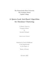
Figure 1: The Pep/7 <strong>Simulator</strong><br />
• Pep/7<br />
The Pep/7 simulator, shown in Figure 1, was written as supporting material <strong>for</strong> J.<br />
Stanley War<strong>for</strong>d’s text, Computer Systems [9]. This book takes a “top down”<br />
approach to computer architecture, starting at <strong>the</strong> application level, and descending<br />
through <strong>the</strong> computer level hierarchy to <strong>the</strong> gate level. Because of this, much of<br />
War<strong>for</strong>d’s focus is on system software and assembly language programming. The<br />
design of Pep/7 is consistent with War<strong>for</strong>d’s pedagogical objectives. The simulator<br />
is mature software, incorporating many features that are helpful to <strong>the</strong> student:<br />
◊ A student can step through program, one instruction at a time.<br />
◊ Breakpoints can be set in <strong>the</strong> code, thus allowing fast execution to <strong>the</strong> location<br />
of <strong>the</strong> instruction of interest.<br />
3
◊<br />
◊<br />
◊<br />
◊<br />
◊<br />
◊<br />
The simulator incorporates a full-featured text processor that includes text<br />
emphasis features such typeface coloring, italicizing, bolding, and font<br />
selection.<br />
Register values are shown in hexadecimal, with binary and character<br />
equivalents given <strong>for</strong> some (not all) registers.<br />
The assembly listing is realistic, giving hexadecimal translations of <strong>the</strong><br />
program instructions on <strong>the</strong> same line as <strong>the</strong> mnemonic instruction.<br />
A symbol table (without cross-references) is provided along with <strong>the</strong><br />
assembler listing.<br />
Printing facilities are well integrated into <strong>the</strong> simulator.<br />
“Friendly” features include an intuitive interface, and confirmation prompts<br />
upon issuance of a program termination command.<br />
Pep/7 is arguably not <strong>the</strong> best teaching tool <strong>for</strong> presenting a detailed examination of<br />
a von Neumann architecture. In particular:<br />
◊ The internal machine operation is viewable only in trace mode.<br />
◊ Trace mode provides only a single-instruction "step mode" and a run mode,<br />
with no provision <strong>for</strong> running a program automatically in "slow motion."<br />
◊ It is difficult to establish a correlation between source statements and machine<br />
events, because <strong>the</strong> symbolic instructions are presented in a separate window<br />
that is encroached upon by <strong>the</strong> system monitor.<br />
◊ To examine <strong>the</strong> contents of memory, <strong>the</strong> user must enumerate <strong>the</strong> addresses to<br />
be traced prior to running <strong>the</strong> program, and only ten addresses can be<br />
specified. The difficulty with this is that some beginning students may not<br />
know which addresses will be accessed prior to initial program execution.<br />
4
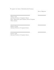
Figure 2: The xComputer<br />
• xComputer<br />
The xComputer, shown in Figure 2, is a Java applet [10] that supports David J.<br />
Eck’s delightful text, The Most Complex Machine [11]. This book introduces<br />
computer science majors to computing in general. The text is equally suitable as a<br />
basic text <strong>for</strong> non-majors. The simulator that Eck provides is colorful and inviting<br />
to student experimentation.<br />
The xComputer is also available as a standalone Java application, however, we<br />
found its use of deprecated (i.e., obsolete) Java classes presented insurmountable<br />
difficulties when compiling <strong>the</strong> programs. (These problems could surely have been<br />
resolved with sufficient perseverance, but this is not a task that is consistent with<br />
<strong>the</strong> assumed skills of <strong>the</strong> simulator’s neophyte users.) Thus, only <strong>the</strong> applet version<br />
is readily available to most students. The main difficulty presented by <strong>the</strong> applet-<br />
5
only version is that xComputer program files cannot be saved or retrieved through<br />
<strong>the</strong> simulator. (This is a Java applet restriction.) Students must <strong>the</strong>re<strong>for</strong>e provide<br />
<strong>the</strong>ir own source file management through o<strong>the</strong>r text-based editors. (The source<br />
code can be copied and pasted into <strong>the</strong> simulator’s editor.) The simulator does,<br />
however, possess some excellent features:<br />
◊ Navigation between <strong>the</strong> main part of <strong>the</strong> simulator and <strong>the</strong> editor is simple and<br />
intuitive.<br />
◊ Two stepping modes are available through control buttons. The “Step” button<br />
causes <strong>the</strong> execution of one machine step of an instruction. Thus, several<br />
"steps" are required to complete a single assembly language instruction. A<br />
“Cycle” button (named <strong>for</strong> fetch-decode-execute cycle) executes an entire<br />
instruction.<br />
◊ Five simulator speeds are available, thus allowing program execution to be<br />
observed in “slow motion” without continual interaction by <strong>the</strong> user.<br />
◊ Memory can be displayed as decimal integers (signed or unsigned), binary<br />
numbers, ASCII characters, or as graphic symbols. The user may also switch<br />
from <strong>the</strong> memory window display to a control wire signal display.<br />
◊ Registers can be displayed in binary, signed decimal or unsigned decimal.<br />
◊ By default, <strong>the</strong> instruction register presents <strong>the</strong> mnemonic <strong>for</strong>m of <strong>the</strong><br />
currently executing instruction.<br />
◊ The memory observation window can be set to autoscroll, so <strong>the</strong> student<br />
doesn’t have to worry about which address should be moved into <strong>the</strong> window.<br />
◊ As instructions are executed, <strong>the</strong> location of <strong>the</strong> instruction (or data) is<br />
highlighted.<br />
The xComputer simulator provides a clear depiction of a simple von Neumann<br />
architecture that bears much resemblance to <strong>MARIE</strong>. Two significant limitations of<br />
this simulator are:<br />
◊ The xComputer is (easily) runnable only as an applet, causing difficulties with<br />
loading, saving, and printing assembly language files.<br />
◊ No hexadecimal translations are available <strong>for</strong> registers or memory.<br />
6
◊<br />
The assembly "listing" provides only mnemonic code, with no hexadecomal<br />
equivalents, and, accordingly, no symbol table is produced as an aid to tracing<br />
and debugging.<br />
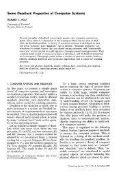
Figure 3: The Ant Debugger<br />
• Ant<br />
The Ant machine is a von Neumann architecture invented <strong>for</strong> general pedagogical<br />
purposes by a group of Harvard University researchers [12][13]. Like <strong>the</strong><br />
xComputer, Ant is aimed at rein<strong>for</strong>cing concepts of computer organization and<br />
architecture as it is taught to beginning computer science and engineering students.<br />
At this writing, we are aware of no textbooks that expressly incorporate <strong>the</strong> Ant<br />
simulator architecture into a discussion of <strong>the</strong> von Neumann architecture.<br />
7
The Ant architecture and its debugger (simulator) are useful teaching tools. There<br />
are two versions of Ant, Ant-8 and Ant-32. The 32-bit version contains advanced<br />
features (virtual memory and system calls, <strong>for</strong> example) that are aimed at advanced<br />
architecture and programming language courses. Ant-8 closely resembles <strong>MARIE</strong><br />
in that it has a limited fixed-length instruction set and only a few registers. Like<br />
<strong>MARIE</strong>, Ant is a simple system designed to illuminate basic computer concepts <strong>for</strong><br />
beginning computer science majors.<br />
Ant’s debugger provides a simulation environment analogous to MarieSim. The<br />
Ant debugger, shown in Figure 3, provides a number of features that compare<br />
favorably with <strong>the</strong> xComputer and Pep/7 simulator:<br />
◊ The layout and presentation are clear in <strong>the</strong>ir purpose and meaning.<br />
◊ A simple integrated editor is provided.<br />
◊ Input and output can be in binary hex, or ASCII. (Like many real systems,<br />
program instructions determine <strong>the</strong> <strong>for</strong>mat of <strong>the</strong> output and expected input.)<br />
◊ The source code panel scrolls automatically, keeping <strong>the</strong> currently executing<br />
instruction always within easy sight.<br />
◊ Instructions and memory locations are highlighted as <strong>the</strong>y are accessed, thus<br />
maintaining a connection between <strong>the</strong> instructions and <strong>the</strong>ir effects upon <strong>the</strong><br />
machine.<br />
◊ Register and memory contents are shown in hexadecimal, ra<strong>the</strong>r than in<br />
decimal.<br />
◊ Ant provides code breakpoint assembly instructions and also allows<br />
breakpoints to be set during debugger execution. .<br />
◊ A step mode is available.<br />
◊ Three execution speeds are available.<br />
There are, however, ways in which its usability could be improved: Ant’s user<br />
interface could be more intuitive. Specifically:<br />
◊ Register values are given only in hexadecimal. No radix translations to<br />
binary, decimal or character are provided.<br />
8
◊<br />
◊<br />
◊<br />
The assembler provides no symbol map or assembly listing.<br />
There is no direct printing facility.<br />
The simulator fails to ask <strong>the</strong> user <strong>for</strong> confirmation upon terminating <strong>the</strong><br />
program. It is too easy to inadvertently close <strong>the</strong> program’s window.<br />
We feel that MarieSim incorporates <strong>the</strong> best features offered by <strong>the</strong> Pep/7, xComputer,<br />
and Ant simulators. We have added features to this baseline functionality that improve<br />
usability and realism without increasing complexity or raising <strong>the</strong> student’s learning<br />
curve. As a result, MarieSim provides an easy-to-use, visually-appealing environment<br />
that provides maximum learning support <strong>for</strong> <strong>the</strong> student. It illuminates and rein<strong>for</strong>ces <strong>the</strong><br />
simple architecture of <strong>the</strong> <strong>MARIE</strong> computer, which we describe in detail in <strong>the</strong> next<br />
section.<br />
9
2 <strong>MARIE</strong>: A Simple Machine <strong>Architecture</strong><br />
The <strong>MARIE</strong> system organization, shown graphically in Figure 4, includes <strong>the</strong> essential<br />
components of a one-address, von Neumann machine with <strong>the</strong> following characteristics:<br />
• Binary, two's complement data representation.<br />
• Stored program, fixed word length data and instructions.<br />
• 4K words of main memory (12 bits per address).<br />
• 16-bit data words.<br />
• 16-bit instructions, 4 <strong>for</strong> <strong>the</strong> opcode and 12 <strong>for</strong> <strong>the</strong> address.<br />
• A 16-bit arithmetic logic unit (ALU).<br />
• Seven registers <strong>for</strong> control and data movement.<br />
Figure 4: The Organization of <strong>MARIE</strong><br />
2.1 Registers and Buses<br />
<strong>MARIE</strong>’s seven registers are <strong>the</strong> minimal set required to support this simple architecture.<br />
These registers are <strong>the</strong>:<br />
• Accumulator, AC, a 16-bit register that holds a conditional operator (e.g., “less<br />
than”) or one operand of a two-operand instruction.<br />
• Memory address register, MAR, a 14-bit register that holds <strong>the</strong> memory address<br />
of an instruction or <strong>the</strong> operand of an instruction.<br />
10
• Memory buffer register, MBR, a 16-bit register that holds <strong>the</strong> data after its<br />
retrieval from, or be<strong>for</strong>e its placement in memory.<br />
• Program counter, PC, a 14-bit register that holds <strong>the</strong> address of <strong>the</strong> next program<br />
instruction to be executed.<br />
• Instruction register, IR, which holds an instruction immediately preceding its<br />
execution.<br />
• Input register, InREG, an 8-bit register that holds data read from an input device.<br />
• Output register, OutREG, an 8-bit register, that holds data that is ready <strong>for</strong> <strong>the</strong><br />
output device<br />
Unlike most general-purpose systems, <strong>MARIE</strong> contains no user-addressable registers.<br />
For instructions requiring two operands, such as <strong>the</strong> ADD instruction, one operand must<br />
be in <strong>the</strong> accumulator, and <strong>the</strong> o<strong>the</strong>r in memory. The accumulator stores <strong>the</strong> results of all<br />
arithmetic operations.<br />
The input and output registers “automatically” convert input and output between humanreadable<br />
numerals or characters and machine-readable binary and vice versa. Computer<br />
system input and output operations are nontrivial, requiring I/O handlers and hardware<br />
interfaces. To maintain utmost simplicity, however, we consciously chose to omit <strong>the</strong><br />
requisite details of this process. This design choice is also made clear in [1].<br />
2.2 The Data Path<br />
The <strong>MARIE</strong> machine contains a single 16-bit bus that conveys bytes to and from <strong>the</strong><br />
registers and memory. No bus arbitration protocol is required owing to <strong>MARIE</strong>’s singlethread<br />
design. All data movement occurs under <strong>the</strong> direct control of a single program<br />
running in memory. Each register connected to <strong>the</strong> bus is identified by a number, from 1<br />
through 7, as shown in Figure 5. Main memory is located at Bus Address 0. Thus, three<br />
control lines are required <strong>for</strong> device addressing, and a fourth to indicate direction. A<br />
register or main memory may place data on <strong>the</strong> bus only when its number is enabled on<br />
<strong>the</strong> control lines.<br />
11
Figure 5: The <strong>MARIE</strong> Data Path<br />
To speed up execution, separate pathways are provided between <strong>the</strong> MAR and memory;<br />
from <strong>the</strong> MBR to <strong>the</strong> AC; and from <strong>the</strong> MBR to <strong>the</strong> ALU. In<strong>for</strong>mation can also flow<br />
from <strong>the</strong> AC, through <strong>the</strong> ALU and back into <strong>the</strong> AC without being put on <strong>the</strong> common<br />
bus. The advantage gained using <strong>the</strong>se additional pathways is that in<strong>for</strong>mation can be put<br />
on <strong>the</strong> common bus in <strong>the</strong> same clock cycle that data is put on <strong>the</strong>se o<strong>the</strong>r pathways,<br />
allowing <strong>the</strong>se events can take place in parallel. For pedagogical purposes, <strong>the</strong>se separate<br />
pathways also provide a more interesting and somewhat realistic register transfer<br />
language.<br />
12
2.3 The Instruction Set <strong>Architecture</strong><br />
<strong>MARIE</strong> supports 16-bit instructions. The most significant 4 bits, bits 12-15, comprise <strong>the</strong><br />
opcode that specifies <strong>the</strong> instruction to be executed (which allows <strong>for</strong> a total of 16<br />
instructions). The least significant 12 bits, bits 0-11, <strong>for</strong>m an address, which allows <strong>for</strong> a<br />
maximum memory address of 2 12 - 1. The instruction <strong>for</strong>mat <strong>for</strong> <strong>MARIE</strong> is shown in<br />
Figure 6. Figure 7 depicts <strong>the</strong> <strong>MARIE</strong> instructions, along with <strong>the</strong> register transfer<br />
language corresponding to <strong>the</strong> instruction.<br />
Figure 6: The <strong>MARIE</strong> Instruction Format<br />
The <strong>MARIE</strong> instruction set includes memory access (LOAD and STORE) instructions,<br />
arithmetic (ADD and SUBTract) instructions, input and output (INPUT and OUTPUT),<br />
execution flow control (JUMP and HALT), and an instruction to set <strong>the</strong> accumulator to<br />
zero (CLEAR). Binary operations expect to find one operand in <strong>the</strong> accumulator and <strong>the</strong><br />
o<strong>the</strong>r at <strong>the</strong> memory address specified within <strong>the</strong> instruction. Conditional branching is<br />
controlled by <strong>the</strong> SKIPCOND instruction. SKIPCOND employs a binary conditional<br />
operand in <strong>the</strong> address field of <strong>the</strong> instruction: If <strong>the</strong> first two bits in <strong>the</strong> address field are<br />
zeroes, and <strong>the</strong> accumulator is negative, <strong>the</strong> instruction that follows <strong>the</strong> SKIPCOND<br />
statement is skipped. Likewise, if <strong>the</strong> first two bits of <strong>the</strong> address field are 01, and <strong>the</strong><br />
accumulator is zero, or if <strong>the</strong> first two bits of <strong>the</strong> address field are 10 and <strong>the</strong> accumulator<br />
is positive. O<strong>the</strong>rwise, execution continues with <strong>the</strong> next program statement.<br />
13
Opcode Instruction Register Transfer Language<br />
0000 JnS X MBR PC<br />
MAR X<br />
M[MAR] MBR<br />
MBR X<br />
AC 1<br />
AC AC + MBR<br />
PC AC<br />
0001 Load X MAR X<br />
MBR M[MAR], AC MBR<br />
0010 Store X MAR X, MBR AC<br />
M[MAR] MBR<br />
0011 Add X MAR X<br />
MBR M[MAR]<br />
AC AC + MBR<br />
0100 Subt X MAR X<br />
MBR M[MAR]<br />
AC AC – MBR<br />
0101 Input AC InREG<br />
0110 Output OutREG AC<br />
0111 Halt<br />
1000 Skipcond If IR[11-10] = 00 <strong>the</strong>n<br />
If AC < 0 <strong>the</strong>n PC PC+1<br />
Else If IR[11-10] = 01 <strong>the</strong>n<br />
If AC = 0 <strong>the</strong>n PC PC + 1<br />
Else If IR[11-10] = 10 <strong>the</strong>n<br />
If AC > 0 <strong>the</strong>n PC PC + 1<br />
1001 Jump X PC IR[11-0]<br />
1010 Clear AC 0<br />
1011 AddI X MAR X<br />
MBR M[MAR]<br />
MAR MBR<br />
MBR M[MAR]<br />
AC AC + MBR<br />
1100 JumpI X MAR X<br />
MBR M[MAR]<br />
PC MBR<br />
Figure 7: The Complete <strong>MARIE</strong> Instruction Set with Register Transfer Language<br />
There are three indirect addressing mode instructions in <strong>MARIE</strong>. These instructions<br />
were included in <strong>the</strong> instruction set <strong>for</strong> <strong>the</strong> sole purpose of demonstrating <strong>the</strong> concept of<br />
indirect addressing and to permit limited subroutine functionality. The ADDI (add<br />
indirect) instruction assumes that <strong>the</strong> address of <strong>the</strong> address of <strong>the</strong> second operand. The<br />
JUMPI (jump indirect) instruction operates similarly using a branch instruction. Limited<br />
14
subroutine functionality is provided by <strong>the</strong> JNS (jump and store) instruction. The return<br />
address is stored in <strong>the</strong> memory location specified by <strong>the</strong> operand. Execution proceeds<br />
with <strong>the</strong> instruction immediately following <strong>the</strong> address specified. When <strong>the</strong> “subroutine”<br />
completes, a JUMPI instruction (that points to this stored address) is issued to provide<br />
<strong>the</strong> “return” from <strong>the</strong> subroutine.<br />
This limited instruction set is sufficient to allow students to experience assembly<br />
language programming, without overwhelming <strong>the</strong>m with <strong>the</strong> complexity of instruction<br />
set architectures characteristic of real machines.<br />
15
3 Significance <strong>for</strong> Computer Science Students<br />
The value of computer architecture simulation and visualization software is well<br />
documented in <strong>the</strong> literature. (See [14], [15], and [16].) Wolffe, et. al. [16] state that <strong>the</strong><br />
use of architecture simulators is gaining popularity <strong>for</strong> <strong>the</strong> following reasons:<br />
1. Students can see <strong>the</strong> computer through various levels of abstraction.<br />
2. Simulation software is more readily available to students—non-traditional<br />
students, in particular—than conventional campus-based computer labs.<br />
3. <strong>Simulator</strong>s are available <strong>for</strong> numerous advanced topics.<br />
4. Many textbooks incorporate simulators <strong>for</strong> topical rein<strong>for</strong>cement and<br />
motivation.<br />
5. Much simulation software is freely available.<br />
To this list, we would add that simulation software is a product of known behavior over<br />
which <strong>the</strong> instructor has control. Installation of revisions to simulator software can be<br />
managed in accordance with <strong>the</strong> academic calendar. This is not always <strong>the</strong> case with<br />
physical systems. Upgrades to <strong>the</strong> hardware and software can occur without an<br />
instructor’s knowledge, causing hasty, “last minute” adjustments to course lectures and<br />
materials that could confuse and frustrate students.<br />
Ultimately, simulators provide a safe and inviting environment within which students can<br />
experience a computer system. Learning is by doing, thus providing a vehicle <strong>for</strong> all<br />
learning styles. MarieSim provides an intuitive graphical environment within which<br />
students can create <strong>the</strong>ir own real, runnable, programs. Through <strong>the</strong>ir own ef<strong>for</strong>ts,<br />
students can observe <strong>the</strong> effects of <strong>the</strong>ir instructions upon <strong>the</strong> state of <strong>the</strong> machine.<br />
Through hands-on experience with an uncomplicated machine, <strong>the</strong> lessons become clear.<br />
16
4 MarieSim, The <strong>MARIE</strong> <strong>Simulator</strong><br />
MarieSim, is a Java-based, graphical software machine that illustrates <strong>the</strong> operation of <strong>the</strong><br />
<strong>MARIE</strong> architecture described in Section 3. Its goal is to provide an intuitive and<br />
visually appealing environment that will encourage student understanding and<br />
experimentation.<br />
4.1 Description<br />
The principal component of MarieSim is <strong>the</strong> virtual machine environment with which<br />
students interact. All components of <strong>the</strong> system, registers, instructions, and memory, are<br />
visible on <strong>the</strong> screen simultaneously. Fur<strong>the</strong>rmore, source instructions are displayed in a<br />
separate panel within <strong>the</strong> simulator allowing <strong>the</strong> student to see <strong>the</strong> symbolic instructions<br />
along with <strong>the</strong>ir hexadecimal memory equivalent. No additional keystrokes (or mouse<br />
clicks) are required to show memory versus instructions.<br />
Execution speed is controllable through menu options, and a single-step mode is<br />
available. Breakpoints can be set by clicking checkboxes within <strong>the</strong> instruction display<br />
window. For ease of understanding, all register displays, as well as input and output, can<br />
be read or displayed in hexadecimal, decimal, or as <strong>the</strong> ASCII character equivalents of<br />
<strong>the</strong> numeric values. The output <strong>for</strong>mat of each register can be set independently of <strong>the</strong><br />
o<strong>the</strong>rs. When <strong>the</strong> simulator is running a program, <strong>the</strong> relevant program instruction is<br />
highlighted in <strong>the</strong> instruction window, as is <strong>the</strong> memory location corresponding to <strong>the</strong><br />
value displayed in <strong>the</strong> memory address register.<br />
By highlighting each instruction as it executes, and its memory location, MarieSim draws<br />
an animated and graphic correspondence between an instruction and its effects upon <strong>the</strong><br />
state of <strong>the</strong> machine.<br />
4.2 Design Decisions<br />
MarieSim is written in Java and Java Swing. The primary reason <strong>for</strong> this choice is that<br />
Java Virtual Machines (Java bytecode interpreters) have been written <strong>for</strong> every type of<br />
17
eal machine that one could reasonably expect to be available to university students. A<br />
second consideration is that Java includes a rich set of features and functions that are not<br />
provided by most o<strong>the</strong>r popular languages. Third, <strong>the</strong> use of Java makes MarieSim<br />
extensible in many ways owing to <strong>the</strong> popularity of <strong>the</strong> language. (See Section 5.)<br />
The overarching design goal of <strong>the</strong> <strong>MARIE</strong> simulator was to provide an inviting and<br />
intuitive environment <strong>for</strong> students to interact with a simple, hypo<strong>the</strong>tical machine. The<br />
purpose of <strong>the</strong> simulator is to rein<strong>for</strong>ce von Neumann machine concepts. Thus, every<br />
ef<strong>for</strong>t was made to reduce <strong>the</strong> learning curve with regard to interaction with <strong>the</strong> simulator<br />
itself. Virtually all operational features are explained through help texts, or are congruent<br />
with operation of o<strong>the</strong>r software with which <strong>the</strong> student is expected to be familiar. (For<br />
example, if one desires to load a file, one does so by pressing <strong>the</strong> “File” button on <strong>the</strong><br />
menu bar at <strong>the</strong> top of <strong>the</strong> simulator.) <strong>Simulator</strong> controls are enabled and disabled in<br />
accordance with <strong>the</strong> state of <strong>the</strong> simulator. For example, <strong>the</strong> “Stop” button is enabled<br />
only when <strong>the</strong> machine is running, and <strong>the</strong> “Run” button is enabled only when <strong>the</strong><br />
machine is halted and an executable program is loaded.<br />
MarieSim’s various panel backgrounds consist of soft colors that are easy on <strong>the</strong> eyes.<br />
Meaningful content (e.g., register values) is shown in dark, bold colors. Source code and<br />
memory contents are traced with bright highlights, thus providing sufficient contrast <strong>for</strong><br />
users who may have color vision impairments [17], or who may be using monitors with<br />
limited color resolution.<br />
The simulator layout includes as much of <strong>the</strong> machine on <strong>the</strong> screen as possible.<br />
Supplementary functions, such as text editing, code assembly, and execution speed<br />
controls are provided through popup windows or drop down menus. To make room <strong>for</strong><br />
all of this, <strong>the</strong> view of <strong>the</strong> instructions and memory had to be limited. However, memory<br />
contents and mnemonic instructions are both displayed in separate scrollable panes.<br />
Thus, while <strong>the</strong> student cannot see <strong>the</strong> entire contents of memory, or <strong>the</strong> entire program<br />
in its mnemonic <strong>for</strong>m, <strong>the</strong> simulator will automatically scroll to each instruction as it<br />
executes, and to each memory location as it is accessed.<br />
18
The most vexing design decision involved <strong>the</strong> <strong>for</strong>mat of <strong>the</strong> assembled, executable<br />
<strong>MARIE</strong> program files. As currently implemented, <strong>the</strong> <strong>MARIE</strong> assembler produces a<br />
Java class file as output. When this class file is created by an assembler that is compiled<br />
on one machine, it is not directly executable in <strong>the</strong> simulator on a second machine. If two<br />
users wish to share a <strong>MARIE</strong> program, <strong>the</strong> source code must be compiled through <strong>the</strong><br />
simulator that will run it.<br />
The advantage in <strong>the</strong> present approach is that <strong>the</strong> simulator is assured of <strong>the</strong> integrity of<br />
<strong>the</strong> assembled code when it is loaded. It cannot be tampered with, or corrupted, in any<br />
way. Also by using a class file, as opposed to <strong>the</strong> pure binary output of o<strong>the</strong>r assemblers,<br />
<strong>the</strong> source code, in its symbolic <strong>for</strong>m is easily stored along with <strong>the</strong> executable code. The<br />
symbolic code includes instruction mnemonics, user-defined variable names, and code<br />
labels. Certainly to do all of this, it is possible to devise a binary file <strong>for</strong>mat that is not a<br />
Java class file, but in so doing, greater error checking would be required at program load<br />
time within <strong>the</strong> simulator. Thus, in order to provide integrity and functionality, class file<br />
output was selected. If <strong>the</strong> source code is error-free, only a few mouse clicks (issued<br />
from within <strong>the</strong> simulator) are required to produce an executable program file from <strong>the</strong><br />
source code. After successful assembly, we are assured that <strong>the</strong> binary object is runnable<br />
and complete.<br />
4.3 Functionality<br />
As stated above, <strong>the</strong> simulator consists of a collection of programs written in Java and<br />
Java Swing. There are two main components in <strong>the</strong> system: <strong>the</strong> <strong>MARIE</strong> assembler and<br />
<strong>the</strong> <strong>MARIE</strong> graphical simulator environment, MarieSim.<br />
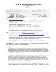
The MarieSim environment, shown in Figure 8, consists of three main parts: A menu bar<br />
that controls operation of <strong>the</strong> simulator, <strong>the</strong> main pane that contains <strong>the</strong> components of<br />
<strong>the</strong> <strong>MARIE</strong> machine, and a message area at <strong>the</strong> bottom of <strong>the</strong> screen to display status and<br />
error messages.<br />
19
The menu bar controls <strong>the</strong> overall operation of <strong>the</strong> simulator. Through <strong>the</strong> menu bar, <strong>the</strong><br />
user loads files, runs programs, sets <strong>the</strong> execution speed, and starts and stops program<br />
execution. Options are also available <strong>for</strong> displaying help text or <strong>the</strong> symbol table of a<br />
loaded program. These options, and <strong>the</strong>ir effects upon <strong>the</strong> simulator, are shown in detail<br />
in <strong>the</strong> user’s guide supplied as Appendix A.<br />
Figure 8: The MarieSim Graphical Environment<br />
MarieSim runs programs written in <strong>MARIE</strong> assembly language. For <strong>the</strong> convenience of<br />
<strong>the</strong> user, MarieSim provides an integrated text editor from which <strong>the</strong> assembler can be<br />
invoked. The <strong>MARIE</strong> assembler is written in Java. It can be used as a standalone<br />
program, or as a callable module. In ei<strong>the</strong>r mode, it expects to be given <strong>the</strong> name of a<br />
<strong>MARIE</strong> assembly code source file, which is a plain text file containing <strong>MARIE</strong> assembly<br />
code having a .MAS file extension. The assembler conducts two passes over <strong>the</strong> source<br />
code. During <strong>the</strong> first pass, source statements from <strong>the</strong> text file are parsed to create a<br />
symbol table containing labels and o<strong>the</strong>r program symbols. An object stream (file)<br />
20
containing partially assembled <strong>MARIE</strong> code, is produced at <strong>the</strong> completion of this first<br />
pass. During <strong>the</strong> second pass of <strong>the</strong> assembler, addresses of <strong>the</strong> program symbols (labels<br />
and variables) are retrieved from <strong>the</strong> symbol table and supplied to <strong>the</strong> code that was<br />
partially assembled during <strong>the</strong> first pass. Upon successful assembly, three files will be<br />
present: a .MEX (<strong>MARIE</strong> Executable) class file <strong>for</strong> <strong>the</strong> program, a .LST plain text<br />
program listing (with mnemonics, symbols and addresses), and a .MAP symbol table<br />
(also plain text) that can be displayed as an aid to <strong>the</strong> user during program execution.<br />
When errors are found in <strong>the</strong> code, a message displays in <strong>the</strong> message area of <strong>the</strong> editor<br />
and <strong>the</strong> assembly listing automatically pops up in a small window. Figure 9 shows <strong>the</strong><br />
integrated editor and assembler with an unsuccessful assembly ef<strong>for</strong>t. Upon receiving<br />
this feedback, <strong>the</strong> student can correct <strong>the</strong> program error and request reassembly through<br />
<strong>the</strong> integrated editor. When assembly is successful, <strong>the</strong> editor also displays a completion<br />
message.<br />
Figure 9: An Unsuccessful Program Assembly<br />
21
To load a <strong>MARIE</strong> executable file into <strong>the</strong> simulator, <strong>the</strong> student selects <strong>the</strong> File|Load<br />
option from <strong>the</strong> menu bar. This action evokes a popup window that displays a listing of<br />
all of <strong>the</strong> <strong>MARIE</strong> executable programs in <strong>the</strong> current directory. The directory may be<br />
changed through Java functionality included in <strong>the</strong> file selection window component.<br />
Figure 10: A Program Loaded and Ready to Run<br />
As <strong>the</strong> <strong>MARIE</strong> executable class file is loaded into <strong>the</strong> simulator, a window containing <strong>the</strong><br />
mnemonic code is populated while its hexadecimal equivalent is loaded into <strong>the</strong> memory<br />
table at <strong>the</strong> bottom of <strong>the</strong> simulator. If <strong>the</strong> mnemonic version of <strong>the</strong> program contains<br />
more than 12 lines, a vertical slider bar will appear on <strong>the</strong> right-hand side of <strong>the</strong><br />
mnemonic code window. Thus, <strong>the</strong> student can scroll through <strong>the</strong> entire program at any<br />
time. All 4096 <strong>MARIE</strong> memory locations are displayed in a similar sliding display at <strong>the</strong><br />
bottom of <strong>the</strong> simulator. (As an aid to <strong>the</strong> student, memory is initialized to all zeroes<br />
each time a new program is loaded.) Figure 10 shows a seven line program that is loaded<br />
22
and ready <strong>for</strong> execution. The first program instruction was loaded at memory location<br />
100h in accordance with an ORiGination instruction placed in <strong>the</strong> source code 1 . The<br />
MarieSim loader always assumes that <strong>the</strong> first line of executable code is <strong>the</strong> first line of<br />
<strong>the</strong> program and sets <strong>the</strong> program counter accordingly.<br />
A stepping mode can be set in <strong>the</strong> simulator to allow <strong>the</strong> student to carefully observe <strong>the</strong><br />
effect that each program instruction has upon <strong>the</strong> state of <strong>the</strong> machine. Selection of <strong>the</strong>se<br />
modes is shown in Figure 11. For long programs or programs with ponderous looping<br />
behavior, <strong>the</strong> single-step mode may prove too tedious, so two additional execution mode<br />
features have been provided. One of <strong>the</strong>se is an option that allows control of <strong>the</strong> delay<br />
between executing consecutive program instructions. The delay feature enables <strong>the</strong><br />
student to see his or her program running in “slow motion.” If <strong>the</strong> slow mode proves<br />
wearisome, <strong>the</strong> student may instead set breakpoints in <strong>the</strong> code simply by checking a box<br />
adjacent to <strong>the</strong> code line of interest in <strong>the</strong> mnemonic program instruction display window,<br />
as shown in Figure 12. If <strong>the</strong> student chooses to just run <strong>the</strong> program (not stepping<br />
through it), <strong>the</strong> “Stop” button at <strong>the</strong> top of <strong>the</strong> simulator is enabled, allowing <strong>for</strong> a “panic<br />
mode” halt to <strong>the</strong> program. This feature will come in handy should an infinite loop<br />
condition arise. (The simulator might not halt instantaneously, because it can only issue a<br />
signal requesting a Java thread process to stop. This event scheduling is not under <strong>the</strong><br />
direct control of <strong>the</strong> simulator.)<br />
1 The ORiGination directive is not specified in <strong>the</strong> textual description of <strong>the</strong> assembler. It was added to <strong>the</strong><br />
functionality of <strong>the</strong> simulator to amplify <strong>the</strong> concept of code relocation and its effects upon symbol<br />
addresses.<br />
23
Figure 11: Program Execution Modes<br />
Figure 12: Breakpoint Program Control<br />
While a program is running, <strong>the</strong> instruction corresponding to <strong>the</strong> value of <strong>the</strong> program<br />
counter is highlighted, along with <strong>the</strong> memory location corresponding to <strong>the</strong> value of <strong>the</strong><br />
memory address register. These highlighted cells are scrolled within <strong>the</strong>ir respective<br />
display panels so that <strong>the</strong>y are visible at all times while <strong>the</strong> program executes. Thus, <strong>the</strong><br />
student can sit back and carefully observe <strong>the</strong> execution of his or her program without<br />
any concern <strong>for</strong> <strong>the</strong> operation of <strong>the</strong> simulator itself.<br />
A student observing or debugging a MarieSim program also has <strong>the</strong> option of displaying<br />
register values in hexadecimal, decimal, or as an ASCII character equivalent (modulo<br />
128). This feature is particularly useful with respect to input and output registers, because<br />
most students are more com<strong>for</strong>table with decimals and characters than <strong>the</strong>y are with <strong>the</strong><br />
hexadecimal numbering system. Character input and output is particularly helpful to<br />
students writing programs that per<strong>for</strong>m any kind of string handling or that solicit<br />
confirmation prompts from <strong>the</strong> user.<br />
The simulator requests confirmation prior to per<strong>for</strong>ming any “destructive” operations,<br />
such as closing <strong>the</strong> simulator. This feedback helps to avoid grave errors such as<br />
eradicating <strong>the</strong> machine state in <strong>the</strong> middle of a lengthy execution trace.<br />
24
In summary, <strong>the</strong> MarieSim environment provides a safe, usable, graphic environment <strong>for</strong><br />
learning von Neumann machine concepts. The simulator has been designed so that<br />
beginning computer users will have little trouble with its operation, allowing <strong>the</strong>m to<br />
focus <strong>the</strong>ir ef<strong>for</strong>ts on writing and debugging <strong>MARIE</strong> assembly language programs.<br />
Observing <strong>the</strong> execution of <strong>the</strong>se instructions promotes a deep understanding of <strong>the</strong><br />
operation of a von Neumann machine.<br />
5 Future Enhancements and Expansions<br />
The Essentials of Computer Organization and <strong>Architecture</strong> text outlines <strong>the</strong> requirements<br />
<strong>for</strong> instruction set architectures that differ from <strong>the</strong> one given <strong>for</strong> <strong>MARIE</strong>. In particular,<br />
various instruction address architectures are given along with <strong>the</strong> requisite changes in <strong>the</strong><br />
instruction <strong>for</strong>mats. Instruction architectures <strong>for</strong> two-address machines and zero address<br />
(stack) machines are outlined. Within <strong>the</strong>se descriptions lies an opportunity <strong>for</strong> students<br />
to experience programming within different machine environments, thus imparting a real<br />
appreciation <strong>for</strong> <strong>the</strong> differences in <strong>the</strong>se architectures. Accordingly, <strong>the</strong> <strong>MARIE</strong> machine<br />
could be recast into two additional and equally simple architectures that support zero- and<br />
two-address instruction sets. Creation of simulators <strong>for</strong> both of <strong>the</strong>se environments would<br />
enlarge a student’s comprehension of <strong>the</strong> differences and similarities between various<br />
instruction set architectures.<br />
With MarieSim, <strong>MARIE</strong> program assembly occurs in <strong>the</strong> background, as a black box<br />
process. Students may benefit by observing real time construction of <strong>the</strong> symbol table<br />
and two-pass assembler operation. This process could also be illuminated through<br />
graphical software that is integrated into <strong>the</strong> simulator.<br />
MarieSim, at this writing, does not offer visibility to <strong>MARIE</strong>’s data path. While registerto-register<br />
and register-to-memory data flows are not particularly difficult concepts to<br />
master, animation software written <strong>for</strong> thus purpose would provide completeness to <strong>the</strong><br />
simulation environment.<br />
25
Surely, as MarieSim gains use in <strong>the</strong> educational environment, additional enhancement<br />
opportunities will present <strong>the</strong>mselves. It is hoped that all future work will continue in <strong>the</strong><br />
spirit of making <strong>the</strong> simulator as easy to use as possible, with an unwavering focus on<br />
providing <strong>the</strong> student <strong>the</strong> clearest possible view of <strong>the</strong> machine and its internal<br />
operations.<br />
26
6 Conclusion<br />
This paper has presented a graphical environment that simulates <strong>the</strong> operation of <strong>the</strong><br />
simple von Neumann machine, <strong>MARIE</strong>, as described in The Essentials of Computer<br />
Organization and <strong>Architecture</strong>. This simulator, MarieSim, animates and rein<strong>for</strong>ces<br />
concepts imparted by <strong>the</strong> text within a safe and inviting environment. MarieSim provides<br />
a host of features to assist <strong>the</strong> student in writing and debugging <strong>MARIE</strong> assembly<br />
language programs. These features include those offered by many o<strong>the</strong>r graphical<br />
simulation systems: register and memory contents displays, program execution speed<br />
control, and stepping mode execution, among o<strong>the</strong>rs. MarieSim augments this essential<br />
functionality by providing an assortment of user tools including: an integrated assembler<br />
that produces realistic assembler listings with symbol maps, breakpoints that can be set<br />
and cleared in real time within <strong>the</strong> execution monitor, execution monitoring that<br />
establishes <strong>the</strong> correspondence between symbolic instructions and <strong>the</strong>ir effects upon <strong>the</strong><br />
machine, as well as register and output displays that can be set independently to show<br />
contents in hexadecimal, binary, or character mode. Above all, MarieSim’s graphical<br />
environment is visually appealing and its operation is straight<strong>for</strong>ward.<br />
MarieSim offers ano<strong>the</strong>r option <strong>for</strong> <strong>the</strong> many educators who wish to incorporate<br />
simulation and visualization software into <strong>the</strong>ir curricula. The reasons <strong>for</strong> employing<br />
virtual systems over real systems are clear and compelling. Thus, <strong>the</strong> use of system<br />
simulators as tools <strong>for</strong> teaching introductory computer organization and architecture is<br />
becoming increasingly accepted, if not expected. Owing to this trend, it would seem that<br />
we are witness to <strong>the</strong> beginning of a new era in computer science education, where<br />
simulation software becomes <strong>the</strong> focus and foundation <strong>for</strong> instructional delivery. By<br />
harnessing and channeling <strong>the</strong> complexity of today's machines, we can provide <strong>the</strong><br />
simplicity and abstraction required to master <strong>the</strong>m.<br />
27
References<br />
[1] Null, L. and Lobur, J. 2003. The Essentials of Computer Organization and<br />
<strong>Architecture</strong>. Jones and Bartlett, Sudbury, MA.<br />
[2] Yurcik, W., Wolffe, G. S., and Holiday, M. A. 2001. “A Survey of <strong>Simulator</strong>s Used<br />
in Computer Organization / <strong>Architecture</strong> Courses.” Summer Conference on Computer<br />
Simulation, Orlando, FL. Society <strong>for</strong> Computer Simulation.<br />
[3] A compendium of computer simulators (<strong>for</strong> <strong>the</strong>oretical, obsolete, and real systems)<br />
can be found at: http://www.sosresearch.org/caale/caalesimulators.html.<br />
[4] Braught, G. and Reed, D. 2001. “The Knob & Switch Computer: A Computer<br />
<strong>Architecture</strong> <strong>Simulator</strong> <strong>for</strong> Introductory Computer Science.” ACM Journal of<br />
Educational Resources in Computing 1, 4, 31 – 45.<br />
[5] Yurcik, W, and Brumbaugh, L. 2001. “A Web-Based Little Man Computer<br />
<strong>Simulator</strong>,” Proceedings of <strong>the</strong> 32nd Technical Symposium on Computer Science<br />
Education (SIGCSE), Charlotte NC USA Feb. 21-25. 204-208.<br />
[6] Yehezke, C., Yurcik, W., Pearson, M., and Armstrong, D. 2001. “Three <strong>Simulator</strong><br />
Tools <strong>for</strong> Teaching Computer <strong>Architecture</strong>: EasyCPU, Little Man Computer, and<br />
RTLSim.” ACM Journal of Educational Resources in Computing 1, 4, 60 – 80.<br />
[7] Menczer, P. and Segre, A. M., 2001. “OAMulator: A Teaching Resource to Introduce<br />
Computer <strong>Architecture</strong> Concepts.” ACM Journal of Educational Resources in Computing<br />
1, 4, 18 – 30.<br />
[8] Grünbacher , H. 1998. “Teaching Computer <strong>Architecture</strong>/Organization Using<br />
<strong>Simulator</strong>s” Proceedings of <strong>the</strong> IEEE Frontiers in Education (FIE) Conference. Tempe,<br />
Arizona. 1107 – 1112.<br />
[9] War<strong>for</strong>d, J. S. 2002. Computer Systems, 2/e. Jones and Bartlett, Sudbury, MA.<br />
[10] The xComputer applet can be launched from:<br />
http://math.hws.edu/TMCM/java/labs/xComputerLab1.html.<br />
[11] Eck, D. J. 1995. The Most Complex Machine: A Survey of Computers and<br />
Computing. A K Peters, Ltd. Wellesley, MA.<br />
[12] Ellard, D., Holland, D., Murphy, N., Seltzer, M. 2002. “On <strong>the</strong> Design of a New<br />
CPU <strong>Architecture</strong> <strong>for</strong> Pedagogical Purposes.” Proceedings of <strong>the</strong> Workshop on Computer<br />
<strong>Architecture</strong> Education, Anchorage, AK. 28-34.<br />
(http://www.csc.ncsu.edu/eos/users/e/efg/wcae/2002/submissions/ellard.pdf)<br />
28
[13] Ellard, D., Ellard, P., Megquier, J., Chen, J. B., Seltzer, M. 1999. “The Ant<br />
<strong>Architecture</strong> - An <strong>Architecture</strong> <strong>for</strong> CS1.” The IEEE Computer Society Technical<br />
Committee on Computer <strong>Architecture</strong> Newsletter. 25-27.<br />
(http://www.ant.harvard.edu/Papers/ellard-tcca99.pdf)<br />
[14] Bruschi, S. M, Santana, R. H.., and Santana, M. J. 1999 “Simulation as a Tool <strong>for</strong><br />
Computer <strong>Architecture</strong> Teaching,” Proceedings of <strong>the</strong> Summer Computer Simulation<br />
Conference, Chicago, IL.<br />
[15] Cassel, L., Kumar, D., Bolding, K. Davies, J., Holliday, M., Impagliazzo, J.,<br />
Pearson, M., Wolfe, G. S., Yurcik, W. 2000. “Distributed Expertise <strong>for</strong> Teaching<br />
Computer Organization and <strong>Architecture</strong>..” ACM SIGCSE Bulletin , 33, 2. 111-126.<br />
[16] Wolffe, G.A., Yurcik, W., Osborne, H., and Holliday, M.A. 2002. "Teaching<br />
Computer Organization/<strong>Architecture</strong> With Limited Resources Using <strong>Simulator</strong>s",<br />
Proceedings of <strong>the</strong> 33rd ACM Symposium on Computer Science Education<br />
(SIGCSE),Technical Symposium, Covington, KY.<br />
[17] Color on <strong>the</strong> Web. http://www.fc.peachnet.edu/facultystaff/irc/webdesign/color.html.<br />
29
Appendix – User’s Guide <strong>for</strong> MarieSim<br />
30
A Guide to <strong>the</strong> <strong>MARIE</strong> Machine <strong>Simulator</strong> Environment<br />
Accompanying The Essentials of Computer Organization and <strong>Architecture</strong><br />
by<br />
Linda Null and Julia Lobur<br />
Version 1.0 – January 2003<br />
Introduction<br />
Your authors have made every ef<strong>for</strong>t to create a <strong>MARIE</strong> machine simulator that is as<br />
Really Intuitive and Easy to use as <strong>the</strong> <strong>MARIE</strong> architecture is to understand. We believe<br />
that <strong>the</strong> best way to gain a deep understanding of <strong>the</strong> <strong>MARIE</strong> machine—or any<br />
computer system <strong>for</strong> that matter—is to write programs <strong>for</strong> it. Toward our goal of<br />
helping you to understand how computers really work, we have created <strong>the</strong> Marie<br />
machine simulator, MarieSim. MarieSim is an environment within which you can write<br />
your own programs and watch how <strong>the</strong>y would run on a real "von Neumann<br />
architecture" computer system. By running programs on this simulator, not only will<br />
you see your programs in action, but you will also get a taste of assembler language<br />
programming without learning any particular assembly language beyond <strong>the</strong> simple<br />
instructions that your authors have presented.<br />
MarieSim was written in <strong>the</strong> Java language so that <strong>the</strong> system would be portable to any<br />
plat<strong>for</strong>m <strong>for</strong> which a Java Virtual Machine (JVM) is available. Students of Java may<br />
wish to look at <strong>the</strong> simulator's source code, and perhaps even supply improvements or<br />
enhancements to its simple functions.<br />
Installation<br />
The <strong>MARIE</strong> machine simulator requires Sun's Java SDK 1.4.0 or later. This software is<br />
available at no charge from <strong>the</strong> java.sun.com Web site. After this package is installed,<br />
<strong>the</strong> Java archive file MarieSim.jar (case sensitive) can be placed in <strong>the</strong> directory of your<br />
choosing. The following command will uncompress <strong>the</strong> archive:<br />
jar xvf MarieSim.jar<br />
If <strong>the</strong> archive uncompresses correctly, you will have <strong>the</strong> main <strong>MARIE</strong> simulator class<br />
file, MarieSim1.class and two <strong>MARIE</strong> code example files in your directory. Jar will also<br />
create two subdirectories, Meta-inf, and Marie<strong>Simulator</strong>. The Marie<strong>Simulator</strong><br />
subdirector contains all of <strong>the</strong> (many) o<strong>the</strong>r classes required <strong>for</strong> simulator operation.<br />
(The Meta-inf subdirectory is created by jar.) Note: The <strong>MARIE</strong> simulator can be run<br />
directly from <strong>the</strong> jar file; however, "Help" and o<strong>the</strong>r text files will not display.<br />
If you also wish to see <strong>MARIE</strong>'s source code, you can obtain <strong>the</strong> MarieSource.jar file<br />
that contains all of <strong>the</strong> Java source <strong>for</strong> <strong>the</strong> Marie simulator. This file is uncompressed<br />
in <strong>the</strong> same way as <strong>the</strong> simulator jar file:<br />
jar xvf MarieSource.jar<br />
The java source will be uncompressed into <strong>the</strong> same directories as <strong>the</strong> class files.<br />
To run <strong>the</strong> <strong>MARIE</strong> machine environment, <strong>the</strong> java classpath must be set to point to <strong>the</strong><br />
directory where <strong>the</strong> MarieSim1.class file is located. For example, if your classpath is<br />
C:\j2sdk1.4.0_01, and you have located <strong>the</strong> MarieSim1.class file in a directory named<br />
A.1
C:\j2sdk1.4.0_01\marie, you must change your classpath to<br />
C:\j2sdk1.4.0_01\marie. Within a Windows environment, you do this by using <strong>the</strong><br />
SET command (set CLASSPATH=C:\j2sdk1.4.0_01\marie). In a Linux/Unix<br />
environment, <strong>the</strong> .cshrc file contains <strong>the</strong> classpath. (Check with your system support<br />
staff if you are unsure as to how to change this file.)<br />
The <strong>MARIE</strong> simulator environment is invoked using <strong>the</strong> command:<br />
java MarieSim1<br />
within <strong>the</strong> directory that contains <strong>the</strong> MarieSim1.class file. (Note: This command is<br />
case sensitive!)<br />
The MarieSim Environment<br />
Figure 1 shows <strong>the</strong> graphical environment of <strong>the</strong> <strong>MARIE</strong> machine simulator. The screen<br />
consists of four parts: a menu bar, a central monitor area, a memory monitor and a<br />
message area.<br />
Figure 1: The MarieSim Graphical Environment<br />
The central monitor area contains a program monitor area, six of <strong>MARIE</strong>'s seven<br />
registers, and an output area, representing <strong>MARIE</strong>'s seventh register.<br />
The memory monitor area displays <strong>the</strong> contents of all 4096 addresses of <strong>MARIE</strong>'s<br />
memory. Each horizontal row of <strong>the</strong> memory area contains 16 memory addresses.<br />
A.2
There<strong>for</strong>e, <strong>the</strong> address labels at <strong>the</strong> left side of <strong>the</strong> memory area are given in increments<br />
of 16, with titles above each column indicating <strong>the</strong> offset from <strong>the</strong> memory address of<br />
each row of memory. For example, <strong>the</strong> memory address DE8 is found in <strong>the</strong> column<br />
labeled +8 of <strong>the</strong> row labeled DE0. All addresses are given in hexadecimal.<br />
As <strong>the</strong> simulator executes your program, <strong>the</strong> instructions in <strong>the</strong> program monitor area<br />
are highlighted along with any memory in <strong>the</strong> memory area that <strong>the</strong> instruction is<br />
accessing. These highlights are most visible (on a fairly "fast" system) when you set a<br />
500 millisecond (or greater) delay between instructions. (See below). With a little<br />
experimentation, you will find an optimal value <strong>for</strong> your system.<br />
During <strong>the</strong> course of executing your program instructions, status messages may appear<br />
in <strong>the</strong> message area at <strong>the</strong> bottom of <strong>the</strong> screen. When your program ends, you will see<br />
ei<strong>the</strong>r a "Program halted normally" or "Program halted abnormally" message. If you<br />
never see this message, ei<strong>the</strong>r your program hasn't started running yet, or it is in a loop<br />
and you'll need to halt it manually.<br />
The MarieSim Controls Menu<br />
The menu at <strong>the</strong> top of <strong>the</strong> simulator gives you control over <strong>the</strong> actions and behavior of<br />
<strong>the</strong> <strong>MARIE</strong> machine <strong>Simulator</strong> system.<br />
The File Menu<br />
The features available through <strong>the</strong> File menu are shown in Figure 2 If you already have<br />
an assembled <strong>MARIE</strong> program at your disposal, all you need to do is load it and run it.<br />
If you want to write a program from scratch, you should select <strong>the</strong> File | Edit option. The<br />
Edit option gives you a simple way to write and assemble programs in <strong>MARIE</strong> assembly<br />
language.<br />
Figure 2: MarieSim File Menu Options<br />
Although you can use any plain text editor (perhaps one with fancier features) to create<br />
your source code, <strong>the</strong> simulator's built-in editor gives you one-button access to <strong>the</strong><br />
assembler. The <strong>MARIE</strong> editor frame is shown in Figure 3.<br />
A.3
The <strong>MARIE</strong> Editor<br />
Once you select File | Edit, and if you do not have a file loaded in <strong>the</strong> simulator (as<br />
shown in Figure 3), <strong>the</strong> editor frame is displayed with a blank text area. If, however,<br />
you have already loaded an assembled file into <strong>the</strong> simulator, <strong>the</strong> source code <strong>for</strong> that<br />
file is automatically brought into <strong>the</strong> editor if <strong>the</strong> editor can locate it.<br />
Figure 3: The MarieSim Editor<br />
<strong>MARIE</strong> assembly code source files must have an ".mas" extension, <strong>for</strong> <strong>MARIE</strong> Assembler.<br />
Both <strong>the</strong> editor and <strong>the</strong> assembler recognize files of this type. Once you have<br />
saved a file with an ".mas" extension, <strong>the</strong> Assemble menu option becomes enabled and<br />
you can assemble your program by selecting <strong>the</strong> Assemble current file menu pick. If you<br />
load an existing ".mas" file, <strong>the</strong> Assemble button is automatically enabled. Any modifications<br />
that you have made to your to your assembly-language file are automatically<br />
saved by <strong>the</strong> editor prior to its invoking <strong>the</strong> assembler. This process is shown in Figure<br />
4, using <strong>the</strong> example from Table 4.5 in <strong>the</strong> text.<br />
A.4
Figure 4: Preparing to Assemble Source Code<br />
Figure 5: An Unsuccessful Assembly<br />
If <strong>the</strong> assembler detects errors in your program, <strong>the</strong> editor sends you a message and <strong>the</strong><br />
assembly listing file appears in a popup frame as shown in Figure 5. All that you need<br />
to do is correct your program and press <strong>the</strong> Assemble current file button once more. If <strong>the</strong><br />
file contains no o<strong>the</strong>r assembler errors, you will see <strong>the</strong> screen shown in Figure 6. If<br />
A.5
you wish, you can display or print <strong>the</strong> assembly listing file, by using <strong>the</strong> editor or any<br />
text-processing program.<br />
The listing file will be placed in <strong>the</strong> currently-logged directory, along with <strong>the</strong> "<strong>MARIE</strong><br />
machine code" file, if assembly was successful. The listing file is a plain-text file with<br />
an ".lst" extension. For example, when Fig4_5.mas is assembled, <strong>the</strong> assembler<br />
produces Fig4-5.lst. You may view it, print it, or incorporate it into ano<strong>the</strong>r document<br />
as you would any plain text file. If assembly is error-free, a ".mex" or <strong>MARIE</strong><br />
EXecutable file will also be placed in <strong>the</strong> same directory as <strong>the</strong> source and listing files.<br />
This is a binary file (actually a serialized Java object) that is executable by <strong>the</strong><br />
simulator.<br />
For example, if your assembly source code is called MyProg.mas, <strong>the</strong> listing file will be<br />
called MyProg.lst and <strong>the</strong> executable will be called MyProg.mex.<br />
Once you have achieved a "clean" assembly of your program, you will see <strong>the</strong> message<br />
shown in Figure 6. If you are satisfied with your program, you can exit <strong>the</strong> editor by<br />
closing its window or selecting File | Exit from <strong>the</strong> menu.<br />
Figure 6: A Successful Assembly<br />
As implied above, <strong>the</strong> <strong>MARIE</strong> editor provides only <strong>the</strong> most basic text-editing functions,<br />
but it is tailored to <strong>the</strong> MarieSim environment. The Help button provides you with some<br />
general help, as well as an instruction set "cheat sheet" that you can use <strong>for</strong> reference<br />
as you write your programs.<br />
The frame in which <strong>the</strong> editor appears may look a little different on your system, but<br />
you can manipulate it as you can with any frame, that is: you can maximize it,<br />
A.6
minimize it, hide it or close it. This is true of all frames spawned by <strong>the</strong> editor as it<br />
responds to your commands.<br />
Loading Your Program<br />
After you have successfully assembled your program, you must load it into <strong>the</strong> simulator<br />
by selecting <strong>the</strong> File | Load menu option from <strong>the</strong> simulator. This option brings up a<br />
file chooser panel that lists all of <strong>the</strong> <strong>MARIE</strong> executable files in your current directory,<br />
and <strong>the</strong> names of o<strong>the</strong>r directories that are available to you. All you need to do is<br />
highlight or type <strong>the</strong> name of <strong>the</strong> file that you wish to run.<br />
Note: Each time you reassemble a file, you must reload it.<br />
Figure 7: A Program Ready to Run<br />
Figure 7 shows <strong>the</strong> <strong>MARIE</strong> simulator after an executable file has been loaded. The<br />
program monitor window shows <strong>the</strong> assembly language statements as <strong>the</strong>y were<br />
written, along with <strong>the</strong>ir hexadecimal equivalents. At <strong>the</strong> left-hand side of <strong>the</strong> program<br />
monitor, you will see <strong>the</strong> addresses of <strong>the</strong> program statements. The statement that has<br />
just been executed by <strong>the</strong> simulator is shown in green highlight, so that you can see <strong>the</strong><br />
effect that <strong>the</strong> instruction has had upon <strong>the</strong> state of <strong>the</strong> machine. Of course, when <strong>the</strong><br />
program is first loaded, <strong>the</strong> green highlight will be on <strong>the</strong> statement at <strong>the</strong> first address<br />
of your program. You will also notice that <strong>the</strong> PC register is set at <strong>the</strong> address of <strong>the</strong><br />
first statement in your program, indicating that this is <strong>the</strong> next statement that will be<br />
run.<br />
Keep in mind that <strong>the</strong> program monitor window is <strong>the</strong>re only to help you visualize what<br />
is going on. The program instructions are, in reality, pulled from <strong>the</strong> memory panel at<br />
A.7
<strong>the</strong> bottom of <strong>the</strong> screen. Once you have loaded your program, you will notice that <strong>the</strong><br />
memory monitor contains <strong>the</strong> hexadecimal program instructions in <strong>the</strong> addresses<br />
corresponding to those in <strong>the</strong> program monitor window. A green highlight will move to<br />
different memory location as your program runs, accessing various storage locations.<br />
Once loaded, your program can be executed using any of three different run options.<br />
The Run Menu<br />
The Run menu offers a number of features that allow you to have control over how your<br />
program is executed by <strong>the</strong> simulator. As shown in Figure 8, <strong>the</strong> first option on this<br />
menu is Run | Run, which executes <strong>the</strong> statements in your program in sequence to<br />
termination. When you select Run | Run, <strong>the</strong> Stop button becomes enabled, giving you<br />
<strong>the</strong> chance to halt your program should it get stuck in a loop or simply is taking too<br />
long to run.<br />
Figure 8 shows <strong>the</strong> Run menu option that you would use to put your program into step<br />
mode. Step mode allows you to execute your program one statement at a time. After<br />
executing each statement, <strong>the</strong> simulator pauses until you press <strong>the</strong> Step button (or <strong>the</strong><br />
program terminates).<br />
Note: If <strong>the</strong> simulator is in step mode, and you subsequently select Run | Run, <strong>the</strong><br />
simulator automatically terminates step mode and enters run mode.<br />
Figure 8: The Run Menu<br />
The Run | Set Delay Option<br />
By default, <strong>the</strong> <strong>MARIE</strong> simulator pauses <strong>for</strong> approximately 10 milliseconds between<br />
subsequent executions of program statements when it is in run mode. The main<br />
purpose <strong>for</strong> this delay is to allow you to halt execution of your program, should you<br />
desire to do so. The delay feature may also be used to allow slow-motion viewing of<br />
your program statements as <strong>the</strong> simulator executes <strong>the</strong>m. You can put <strong>the</strong> simulator in<br />
this slow-motion mode by setting <strong>the</strong> delay to 500 milliseconds or longer.<br />
The delay-setting screen is shown in Figure 9. To change <strong>the</strong> execution delay, just<br />
move <strong>the</strong> slider bar to <strong>the</strong> desired number of milliseconds and press <strong>the</strong> Okay button.<br />
A.8
Figure 9: Setting Execution Delay<br />
Setting <strong>the</strong> slider: As you would expect, you can move <strong>the</strong> slider pointer by clicking and<br />
dragging it with your mouse. You can also move it using <strong>the</strong> cursor-movement keys on<br />
your keyboard. Page Up and Page Down move <strong>the</strong> slider by large increments, and your<br />
left and right arrows move it by smaller increments, allowing <strong>for</strong> precision setting of <strong>the</strong><br />
slider bar.<br />
The Run | Restart Option<br />
The next option under <strong>the</strong> Run menu is <strong>the</strong> option to Restart <strong>the</strong> simulator. This option<br />
simply resets <strong>the</strong> program counter to <strong>the</strong> first address of <strong>the</strong> program that is loaded in<br />
<strong>the</strong> simulator. Any changes that your program may have made to <strong>the</strong> simulator's<br />
memory stay in place.<br />
The Run | Reset Option<br />
To completely start over from scratch, use <strong>the</strong> Run | Reset option. Selecting this option<br />
has <strong>the</strong> same effect as pressing <strong>the</strong> reset key on a personal computer. All memory is<br />
cleared and <strong>the</strong> registers are reset to zero. Because this option eradicates everything in<br />
<strong>the</strong> simulator, you will be asked <strong>for</strong> confirmation be<strong>for</strong>e proceeding with <strong>the</strong> reset<br />
(unlike pressing <strong>the</strong> reset button on most PCs!).<br />
The Run | Core Dump Option<br />
Many computers dump <strong>the</strong> entire contents of <strong>the</strong>ir memory after <strong>the</strong>y encounter certain<br />
severe errors. If you have used Windows NT, you may have experienced <strong>the</strong> famous<br />
"blue screen of death" which appears while <strong>the</strong> system is dumping its memory to a<br />
dump file. When it encounters a fatal error, <strong>the</strong> <strong>MARIE</strong> simulator does not<br />
automatically provide a core dump, you need to request one through <strong>the</strong> Run | Core<br />
Dump menu option. This menu option provides you with <strong>the</strong> popup frame shown in<br />
Figure 10.<br />
A.9
As you can see from <strong>the</strong> figure, <strong>the</strong> popup shows two sliders (which, like <strong>the</strong> delay<br />
slider, can be controlled using cursor keys). The scales on <strong>the</strong> sliders range from 0 to<br />
4095 and are given in decimal. The hexadecimal translation of <strong>the</strong> slider values<br />
appears in <strong>the</strong> text boxes to <strong>the</strong> right of <strong>the</strong> sliders. The initial values of <strong>the</strong> core dump<br />
are set to <strong>the</strong> memory address space occupied by your program. In <strong>the</strong> illustration, our<br />
program occupies memory addresses 100h through 106h. You can move <strong>the</strong>se sliders<br />
to any addresses that you wish.<br />
If you press <strong>the</strong> Okay button from <strong>the</strong> core dump selection frame, ano<strong>the</strong>r frame soon<br />
appears, containing <strong>the</strong> contents of <strong>MARIE</strong>'s registers and <strong>the</strong> memory addresses that<br />
you selected. This screen is shown in Figure 11.<br />
Figure 10: Setting Memory Core Dump Range<br />
Figure 11: A <strong>MARIE</strong> Core Dump<br />
A.10
Be<strong>for</strong>e showing it to you on <strong>the</strong> screen, <strong>the</strong> simulator writes your core dump to a disk<br />
file with a ".dmp" extension. So if <strong>the</strong> name of your program is MyProg.mas, its dump<br />
file will be named MyProg.dmp. It is a plain text file that you can edit using any plain<br />
text editor, if you so desire.<br />
Breakpoints<br />
Breakpoints are flags placed on computer instructions that tell <strong>the</strong> system to pause<br />
execution at <strong>the</strong> instruction where <strong>the</strong> breakpoint is set. Breakpoints are useful<br />
because a long series of instructions can be executed quickly (as in initializing an array,<br />
<strong>for</strong> example) be<strong>for</strong>e <strong>the</strong> system pauses to allow you to inspect <strong>the</strong> contents of registers<br />
and memory be<strong>for</strong>e proceeding. In <strong>the</strong> <strong>MARIE</strong> simulator, breakpoints are set by<br />
clicking on <strong>the</strong> square to <strong>the</strong> left of <strong>the</strong> instruction number in <strong>the</strong> program monitor<br />
area. One such breakpoint has been entered at instruction 101h in <strong>the</strong> program shown<br />
in Figure 12. There is no limit to <strong>the</strong> number of breakpoints that can be set in a<br />
program.<br />
Figure 12: Breakpoint set at 101h and <strong>the</strong> Breakpoint Menu<br />
When you select <strong>the</strong> Breakpoints | Run to Breakpoint menu option, <strong>the</strong> program starts<br />
execution at <strong>the</strong> current value of <strong>the</strong> program counter and proceeds until <strong>the</strong><br />
breakpoint is encountered. Pressing Breakpoints | Run to Breakpoint once more resumes<br />
execution until <strong>the</strong> next breakpoint is encountered or <strong>the</strong> program terminates. If you<br />
select Breakpoints | Run to Breakpoint when <strong>the</strong> program counter is pointing to a halt<br />
instruction, <strong>the</strong> simulator per<strong>for</strong>ms an automatic restart and executes your program<br />
beginning with <strong>the</strong> first instruction.<br />
You may notice that when your program is in Run to Breakpoint mode, <strong>the</strong> Stop button<br />
becomes enabled. This allows you to halt your program if you need to do so. The Run<br />
to Breakpoint option is also mindful of <strong>the</strong> execution delay that you have set in <strong>the</strong><br />
program. So if you have set this delay at 500 ms, <strong>the</strong> simulator will wait approximately<br />
one-half second between each statement.<br />
The Breakpoints | Clear Breakpoints menu option does exactly what you think it would do:<br />
It removes all breakpoints from <strong>the</strong> program instruction monitor. You can also remove<br />
a breakpoint by clicking on its checkmark.<br />
A.11
The Symbol Table<br />
From <strong>the</strong> discussion in your text, you know that one of <strong>the</strong> principal data structures<br />
involved in <strong>the</strong> assembly process is <strong>the</strong> symbol table. <strong>MARIE</strong>'s assembler is no<br />
different. You will see this table at <strong>the</strong> end of your assembly listing, whe<strong>the</strong>r or not<br />
assembly was successful. The <strong>MARIE</strong> simulator also makes this table available to you<br />
right in <strong>the</strong> simulator environment through <strong>the</strong> Symbol Map button. If you are trying to<br />
debug a large program, or a program that contains a considerable number of symbols,<br />
you may want to refer to this table from <strong>the</strong> simulator environment. Figure 13 shows a<br />
symbol table display frame <strong>for</strong> <strong>the</strong> small program loaded in <strong>the</strong> simulator.<br />
Figure 13: Viewing a Symbol Table<br />
Input and Output Modes<br />
You will notice in <strong>the</strong> figures that each register,<br />
as well as <strong>the</strong> OUTPUT pane, is provided<br />
with a pull-down (combo box) that lets you<br />
select <strong>the</strong> display mode of <strong>the</strong> register, ei<strong>the</strong>r<br />
in hexadecimal, decimal or as an ASCII character.<br />
If you request a register to display its<br />
contents in ASCII character mode, <strong>the</strong> contents<br />
of <strong>the</strong> register will be displayed in a<br />
standard 7-bit ASCII modulus over <strong>the</strong> contents<br />
of <strong>the</strong> register. For example, if <strong>the</strong> register<br />
contains a value of 00C1h, <strong>the</strong> ASCII<br />
character displayed will be a capital A. Figure<br />
14 illustrates register mode selection .<br />
The mode selection available <strong>for</strong> <strong>the</strong> output<br />
register (or output pane) will be useful when<br />
you want to see character output. By default,<br />
Figure 14: Setting a Register's Mode<br />
A.12
oth <strong>the</strong> input and output registers are in ASCII mode. So any values that you type in<br />
<strong>the</strong> input register will be interpreted as ASCII characters. For example, if your program<br />
is asking <strong>for</strong> input and you enter 29 while <strong>the</strong> input register is in ASCII mode, only <strong>the</strong><br />
first character of your input will be recognized so <strong>the</strong> value stored in <strong>the</strong> accumulator will<br />
be 32h, which is <strong>the</strong> ASCII value <strong>for</strong> <strong>the</strong> decimal numeral 2. If you wanted to place a<br />
value of 2 into your program, you must set <strong>the</strong> register to decimal or hexadecimal mode.<br />
The values you enter must be appropriate to<br />
<strong>the</strong> register mode, or else you'll get a fatal<br />
error message in <strong>the</strong> simulator, as you would<br />
on a real system.<br />
You will notice that when you change <strong>the</strong><br />
radix mode of <strong>the</strong> output, all of your output<br />
immediately changes to <strong>the</strong> mode that you<br />
have selected, just as it does <strong>for</strong> <strong>the</strong> o<strong>the</strong>r<br />
registers. Figure 15 shows Figure 14 after<br />
<strong>the</strong> hexadecimal mode has been selected.<br />
Ano<strong>the</strong>r useful feature of <strong>the</strong> output pane is<br />
<strong>the</strong> ability to control how <strong>the</strong> output will be<br />
placed in <strong>the</strong> pane. By default, when a value<br />
is output, it is automatically followed by a<br />
linefeed so that <strong>the</strong> output will be a single<br />
column of characters, similar to how<br />
characters print on an adding machine tape.<br />
Figure 15: Re<strong>for</strong>matted Output<br />
If you select <strong>the</strong> No Linefeeds option, as<br />
shown in Figure 16, your output will be<br />
placed horizontally in <strong>the</strong> output pane, from<br />
left to right—with no automatic wrapping.<br />
When <strong>the</strong> No Linefeeds option is turned on,<br />
you will need to programmatically provide<br />
your own linefeeds order to advance <strong>the</strong><br />
output to <strong>the</strong> next line.<br />
Implementation note: Although we have tried<br />
to make <strong>the</strong> <strong>MARIE</strong> <strong>Simulator</strong> behave as much<br />
like a real machine as possible, in <strong>the</strong> area of<br />
output and input we have deviated from this<br />
ideal. Handling input and output at <strong>the</strong><br />
machine level is an enormously tedious task.<br />
Your authors feel that it is counterproductive to<br />
be wrestling with <strong>the</strong>se issues when you're<br />
first learning assembly language programming.<br />
When you're up <strong>for</strong> a challenge, try<br />
using only hexadecimal values <strong>for</strong> input and<br />
no linefeeds on your output!<br />
Figure 16: Setting Linefeeds<br />
Ano<strong>the</strong>r output control option available to you enables you to clear <strong>the</strong> contents of <strong>the</strong><br />
output pane. Unlike <strong>the</strong> o<strong>the</strong>r six registers, <strong>the</strong> contents of <strong>the</strong> output register (pane)<br />
are retained until you explicitly clear it or load a different program.<br />
A.13
You can also print <strong>the</strong> contents of <strong>the</strong> output register, but you may simply want to copy<br />
its contents into a text-handling program. On most systems, you can copy <strong>the</strong> contents<br />
of <strong>the</strong> output area into your system clipboard. The text can <strong>the</strong>n be pasted into any<br />
program that recognizes <strong>the</strong> clipboard.<br />
A Few Words About <strong>the</strong> <strong>MARIE</strong> Assembler<br />
Your book discusses each of <strong>MARIE</strong>'s instructions in detail, so we will not restate <strong>the</strong>m<br />
here. There are, however, a few things particular to <strong>the</strong> assembler that you'll need to<br />
know be<strong>for</strong>e you begin writing your first program.<br />
Assembler Directives<br />
There are four directives that <strong>the</strong> <strong>MARIE</strong> assembler recognizes. The first of <strong>the</strong>se is <strong>the</strong><br />
origination directive, ORG. As stated in Chapter 4, <strong>the</strong> ORG directive controls <strong>the</strong><br />
starting address of your program. If you do not include an ORG directive in your code,<br />
<strong>the</strong> first address of your program is automatically 000h. (Note: On a real machine, you<br />
could not count on this, which is why origination directives are used.) If you want <strong>the</strong><br />
first address of your program to be 010h, you would place <strong>the</strong> directive, ORG 010 at <strong>the</strong><br />
beginning of your program. The ORG directive must be <strong>the</strong> first statement of your<br />
program, o<strong>the</strong>rwise, <strong>the</strong> assembler will give you an error.<br />
The o<strong>the</strong>r three directives enable you to put constants in your program as decimal<br />
(DEC), octal (OCT), and hexadecimal (HEX) numbers. These constants must be valid <strong>for</strong><br />
<strong>the</strong> radix stated in <strong>the</strong> directive. For example, <strong>the</strong> statement, OCT 0900, will give you an<br />
error.<br />
Recall that <strong>MARIE</strong>'s word size is 16 bits, and all constants are assumed to be signed<br />
numbers. There<strong>for</strong>e, <strong>the</strong> valid range of decimal constants is decimal –32,768 to 32,767<br />
(8000h to 7FFFh).<br />
Operands<br />
As you learned in Chapter 4, all <strong>MARIE</strong> operands are addresses. If you use address<br />
literals in your program, <strong>the</strong> valid values are 000h through FFFh, since <strong>MARIE</strong> has<br />
4096 memory locations. These addresses must be given in hexadecimal, preceded by a<br />
zero. So, if you wish to add <strong>the</strong> value at address F00 to <strong>the</strong> accumulator, you would<br />
use <strong>the</strong> instruction, ADD 0F00. If you instead use <strong>the</strong> instruction, ADD F00, <strong>the</strong><br />
assembler will expect to find <strong>the</strong> label F00 somewhere in your program. Unless you<br />
have such an address in your program, <strong>the</strong> assembler will give you an error.<br />
You may prefer to use a symbolic labels instead of address literals. <strong>MARIE</strong>'s labels are<br />
case sensitive and can be of virtually any length (up to <strong>the</strong> limits placed on string<br />
variables by <strong>the</strong> Java language). Be advised, however, that only <strong>the</strong> first 24 characters<br />
of <strong>the</strong> symbol will print on <strong>the</strong> assembly listing and only <strong>the</strong> first 7 characters will be<br />
visible in <strong>MARIE</strong>Sim's program monitor panel.<br />
Code Construction<br />
Assembly language source code files can be of any size, but you can have only as many<br />
program statements as will fit in <strong>the</strong> <strong>MARIE</strong> memory. The program statement count<br />
does not include comments or blank lines. We encourage you to use comments and<br />
blank lines to make your code understandable to humans as well as <strong>the</strong> machine.<br />
A.14
The only o<strong>the</strong>r restriction on your code is that it can begin with only <strong>the</strong> following types<br />
of statements:<br />
1. A comment followed by an origination directive and at least one imperative<br />
statement<br />
2. An origination directive and at least one imperative statement, or<br />
3. At least one imperative statement.<br />
In o<strong>the</strong>r words, your program cannot begin with a DEC, OCT or HEX directive. If it<br />
does, nei<strong>the</strong>r <strong>the</strong> assembler nor <strong>the</strong> simulator will care, but <strong>the</strong> literal values defined by<br />
those directives will be interpreted as instructions by <strong>the</strong> machine, giving you results<br />
that you may not have expected.<br />
A similar problem will arise if you fail to include a HALT statement in your program, or<br />
your HALT statement does not execute, and <strong>the</strong> program counter ends up pointing to<br />
data. (How will <strong>the</strong> machine react if it tries to execute <strong>the</strong> statement HEX 0000? What<br />
about HEX 0700?)<br />
A Summary of File Types<br />
Throughout this guide, we have mentioned <strong>the</strong> various file types that MarieSim uses <strong>for</strong><br />
various functions. For your reference, we have included a summary of <strong>the</strong>se file types<br />
in <strong>the</strong> table below.<br />
File<br />
extension<br />
.mas<br />
.lst<br />
Description Type Created by Used by<br />
Assembly code<br />
source<br />
Assembly listing<br />
file<br />
plain text<br />
plain text<br />
MarieEditor, or<br />
any plain text editor<br />
Assembler<br />
.map Symbol table plain text Assembler<br />
.mex<br />
Executable code<br />
serialized Java<br />
object<br />
Assembler<br />
.dmp Core dump plain text MarieSim<br />
MarieEditor and<br />
Assembler<br />
MarieEditor<br />
(TextFileViewer)<br />
MarieSim<br />
(TextFileViewer)<br />
MarieSim<br />
MarieSim<br />
(TextFileViewer)<br />
Comments, Bugs, and Suggestions<br />
The authors of your text and this simulator invite you to send us comments and<br />
suggestions. We would also like to correct any bugs that you find. You may send your<br />
findings and observations to: ECOA@jbpub.com<br />
If you are reporting a bug, please supply as much in<strong>for</strong>mation as you can with regard to<br />
what <strong>the</strong> simulator was doing when <strong>the</strong> problem occurred. Also, attach <strong>the</strong> .mas file, if<br />
<strong>the</strong> error occurred during program execution. Your comments will enable us to improve<br />
this simulator so that all students can have a positive learning experience.<br />
A.15