Circular Connectors for Printed Circuit Board Applications
Circular Connectors for Printed Circuit Board Applications
Circular Connectors for Printed Circuit Board Applications

Create successful ePaper yourself
Turn your PDF publications into a flip-book with our unique Google optimized e-Paper software.
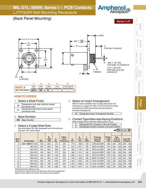
MIL-DTL-38999, Series I – PCB Contacts<br />
LJTPQ00R Wall Mounting Receptacle<br />
(Back Panel Mounting)<br />
S<br />
R<br />
(TP)<br />
T<br />
(4 HOLES)<br />
SS<br />
R<br />
(TP)<br />
S<br />
N<br />
.905<br />
M<br />
.006<br />
.000<br />
P<br />
V<br />
THREAD<br />
Amphenol<br />
Aerospace<br />
L MAX<br />
Z<br />
PCB TAIL STICKOUT<br />
Series I LJT<br />
.062 .001 DIA.<br />
FOR SIZE 16 CONTACTS<br />
.019 .001 DIA.<br />
FOR SIZE 20 & 22D<br />
CONTACTS<br />
38999<br />
III II I SJT<br />
26482 83723 III 5015<br />
Matrix 2<br />
Matrix Pyle<br />
Crimp Rear<br />
Release Matrix<br />
PART #<br />
See chart below<br />
HOW TO ORDER<br />
1. Select a Shell Finish:<br />
88<br />
91<br />
Shell<br />
Size<br />
Designates olive drab cadmium plated<br />
connector shell<br />
Designates electroless nickel plated<br />
connector shell<br />
2. Base Number:<br />
569 Base Number<br />
Part Number<br />
1. 2. 3. 4. 5.<br />
Shell Base Coded Insert Contact Type/Alt.<br />
Finish Number Shell Size Arrangement Keying Positions<br />
88/91 569 701 - 35 P<br />
3. Select a Coded Shell Size:<br />
See chart below 701-709, designates size 9-25 shell size.<br />
Example: 701= Size 9 Shell<br />
L<br />
Max.<br />
M<br />
+.000<br />
–.005<br />
N<br />
Dia.<br />
P Max.<br />
Panel<br />
Thickness<br />
R<br />
(TP)<br />
S<br />
+.011<br />
–.010<br />
T<br />
Dia.<br />
±.005<br />
V Thread<br />
Class 2A<br />
(Plated)<br />
SS Dia.<br />
+.000<br />
–.016<br />
Size<br />
16 & 20<br />
Contacts<br />
Z<br />
Size 22D<br />
Contacts<br />
9 88/91-569701-XXX .453 .820 .572 .234 .719 .938 .128 .4375-28 UNEF .662 .281 – .235 .249 – .188<br />
11 702-XXX .453 .820 .700 .234 .812 1.031 .128 .5625-24 UNEF .810 .281 – .235 .249 – .188<br />
13 703-XXX .453 .820 .850 .234 .906 1.125 .128 .6875-24 UNEF .960 .281 – .235 .249 – .188<br />
15 704-XXX .453 .820 .975 .234 .969 1.219 .128 .8125-20 UNEF 1.085 .281 – .235 .249 – .188<br />
17 705-XXX .453 .820 1.100 .234 1.062 1.312 .128 .9375-20 UNEF 1.210 .281 – .235 .249 – .188<br />
19 706-XXX .453 .820 1.207 .234 1.156 1.438 .128 1.0625-18 UNEF 1.317 .281 – .235 .249 – .188<br />
21 707-XXX .484 .790 1.332 .204 1.250 1.562 .128 1.1875-18 UNEF 1.442 .281 – .235 .249 – .188<br />
23 708-XXX .484 .790 1.457 .204 1.375 1.688 .147 1.3125-18 UNEF 1.567 .281 – .235 .249 – .188<br />
25 709-XXX .484 .790 1.582 .193 1.500 1.812 .147 1.4375-18 UNEF 1.692 .281 – .235 .249 – .188<br />
All dimensions <strong>for</strong> reference only.<br />
Z dimension is determined by contact type in the insert arrangement.<br />
Most common options are shown; other options are available.<br />
4. Select an Insert Arrangement:<br />
Refer to insert availability chart on page 239 and pin-out<br />
illustrations on pages 241-255. In the chart the first number<br />
represents the Shell size and the second number is<br />
the insert Arrangement.<br />
-35 Designates Insert Arrangement Number<br />
5. Contact Type/Alternate Keying Positions:<br />
Refer to page 240 <strong>for</strong> alternate rotation letters to use.<br />
P<br />
S<br />
Designates Pin Contacts in Normal Position<br />
Designates Socket Contacts in Normal Position<br />
+ .005 DIA M<br />
26500 Pyle<br />
<strong>Printed</strong><br />
<strong>Circuit</strong> <strong>Board</strong><br />
EMI Filter<br />
Transient<br />
Fiber Optics<br />
High Speed<br />
Contacts<br />
Options<br />
Others<br />
Contact Amphenol Aerospace <strong>for</strong> more in<strong>for</strong>mation at 800-678-0141 • www.amphenol-aerospace.com<br />
269