Circular Connectors for Printed Circuit Board Applications
Circular Connectors for Printed Circuit Board Applications
Circular Connectors for Printed Circuit Board Applications

You also want an ePaper? Increase the reach of your titles
YUMPU automatically turns print PDFs into web optimized ePapers that Google loves.
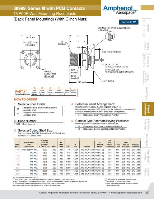
38999, Series III with PCB Contacts<br />
TVP00R Wall Mounting Receptacle<br />
(Back Panel Mounting) (With Clinch Nuts)<br />
S<br />
2 PLACES<br />
LL<br />
Amphenol<br />
Aerospace<br />
Series III TV<br />
CONNECTOR WITH CLINCH NUTS<br />
(4 PLACES)<br />
38999<br />
III II I SJT<br />
R<br />
2 PLACES<br />
T<br />
THREAD<br />
CLINCH NUT<br />
.005 M<br />
B<br />
THREAD<br />
RED<br />
BAND<br />
BLUE<br />
BAND<br />
M<br />
AA<br />
1.240 MAX.<br />
L<br />
Z<br />
PCB TAIL STICKOUT<br />
.062 .001 DIA.<br />
FOR SIZE 16 CONTACTS<br />
.019 .001 DIA.<br />
FOR SIZE 20 & 22D CONTACTS<br />
V THREAD<br />
26482 83723 III 5015<br />
Matrix 2<br />
Matrix Pyle<br />
Crimp Rear<br />
Release Matrix<br />
PART #<br />
See chart below<br />
HOW TO ORDER<br />
1. Select a Shell Finish:<br />
88<br />
91<br />
Shell<br />
Size<br />
Designates olive drab cadmium plated<br />
connector shell<br />
Designates electroless nickel plated<br />
connector shell<br />
2. Base Number:<br />
628 Base Number<br />
Part Number<br />
with<br />
Clinch Nuts*<br />
1. 2. 3. 4. 5.<br />
Shell Base Coded Insert Contact Type/Alt.<br />
Finish Number Shell Size Arrangement Keying Positions<br />
88/91 628 741 - 35 P<br />
3. Select a Coded Shell Size:<br />
See chart below 741-749, designates size 9-25 shell size.<br />
Example: 741= Size 9 Shell<br />
B Thread<br />
Class 2A<br />
(Plated)<br />
0.1P-0.3L-TS<br />
L<br />
Max.<br />
M<br />
+.000<br />
–.005 R<br />
4. Select an Insert Arrangement:<br />
Refer to insert availability chart on page 239 and pin-out<br />
illustrations on pages 241-255. In the chart the first number represents the<br />
Shell size and the second number is the insert Arrangement.<br />
5. Contact Type/Alternate Keying Positions:<br />
Refer to page 240 <strong>for</strong> alternate rotation letters to use.<br />
S<br />
Max.<br />
T<br />
Thread<br />
V<br />
Thread<br />
Metric<br />
AA<br />
Max.<br />
Panel<br />
Thickness<br />
LL<br />
+.006<br />
–.000<br />
Size<br />
16 & 20<br />
Contacts<br />
Z<br />
Size 22D<br />
Contacts<br />
9 88/91-628741-XXX .6250 .469 .820 .719 1.094 .112-40UNC-3B M12X1-6g .234 .905 .228–.178 .242–.181<br />
11 742-XXX .7500 .469 .820 .812 1.187 .112-40UNC-3B M15X1-6g .234 .905 .228–.178 .242–.181<br />
13 743-XXX .8750 .469 .820 .906 1.281 .112-40UNC-3B M18X1-6g .234 .905 .228–.178 .242–.181<br />
15 744-XXX 1.0000 .469 .820 .969 1.344 .112-40UNC-3B M22X1-6g .234 .905 .228–.178 .242–.181<br />
17 745-XXX 1.1875 .469 .820 1.062 1.437 .112-40UNC-3B M25X1-6g .234 .905 .228–.178 .242–.181<br />
19 746-XXX 1.2500 .469 .820 1.156 1.531 .112-40UNC-3B M28X1-6g .234 .905 .228–.178 .242–.181<br />
21 747-XXX 1.3750 .500 .790 1.250 1.625 .112-40UNC-3B M31X1-6g .204 .905 .228–.178 .242–.181<br />
23 748-XXX 1.5000 .500 .790 1.375 1.750 .138-32UNC-3B M34X1-6g .204 .905 .228–.178 .242–.181<br />
25 749-XXX 1.6250 .500 .790 1.500 1.875 .138-32UNC-3B M37X1-6g .204 .905 .228–.178 .242–.181<br />
All dimensions <strong>for</strong> reference only.<br />
*Consult Amphenol <strong>for</strong> more in<strong>for</strong>mation on ordering connectors with clinch nuts.<br />
Composite Series III connectors with PBC Contacts are available; consult Amphenol, Sidney, NY.<br />
Z dimension is determined by contact type in the insert arrangement.<br />
Most common options are shown; other options are available.<br />
-35 Designates Insert Arrangement Number<br />
P<br />
S<br />
Designates Pin Contacts in Normal Position<br />
Designates Socket Contacts in Normal Position<br />
Designates true position dimensioning<br />
† Red band indicates fully mated<br />
†† Blue band indicates rear release contact<br />
retention system<br />
26500 Pyle<br />
<strong>Printed</strong><br />
<strong>Circuit</strong> <strong>Board</strong><br />
EMI Filter<br />
Transient<br />
Fiber Optics<br />
High Speed<br />
Contacts<br />
Options<br />
Others<br />
Contact Amphenol Aerospace <strong>for</strong> more in<strong>for</strong>mation at 800-678-0141 • www.amphenol-aerospace.com<br />
257