Amphenol MIL DTL38999 series1 Connectors.pdf
Amphenol MIL DTL38999 series1 Connectors.pdf
Amphenol MIL DTL38999 series1 Connectors.pdf

You also want an ePaper? Increase the reach of your titles
YUMPU automatically turns print PDFs into web optimized ePapers that Google loves.
<strong>Amphenol</strong><br />
Aerospace<br />
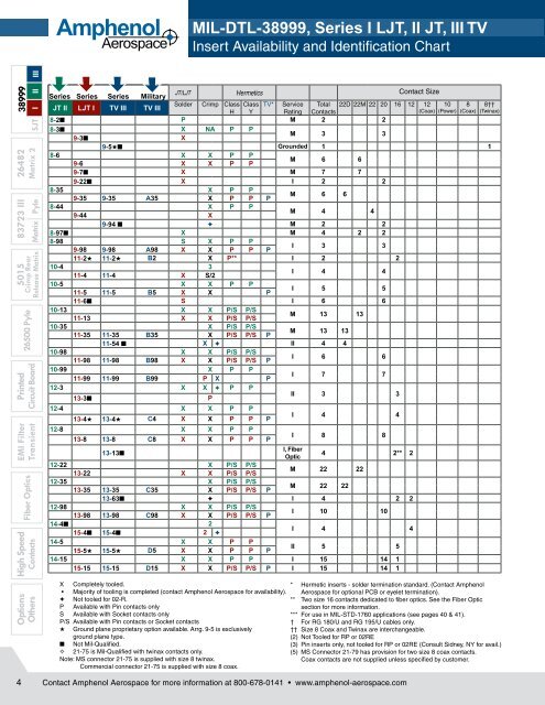
<strong>MIL</strong>-DTL-38999, Series I LJT, II JT, III TV<br />
Insert Availability and Identification Chart<br />
Options High Speed<br />
EMI Filter Printed<br />
5015 83723 III 26482 38999<br />
Others<br />
Fiber Optics<br />
Transient Circuit Board<br />
26500 Pyle Crimp Rear<br />
Contacts Release Matrix Matrix Pyle Matrix 2 SJT I II III<br />
Series Series Series Military<br />
JT/LJT Hermetics Contact Size<br />
JT II LJT I TV III TV III<br />
Solder Crimp Class Class TV* Service Total 22D 22M 22 20 16 12 12 10 8 8††<br />
H Y Rating Contacts<br />
(Coax) (Power) (Coax) (Twinax)<br />
8-2■ P M 2 2<br />
8-3■ X NA P P<br />
9-3■ X<br />
M 3 3<br />
9-5★■ Grounded 1 1<br />
8-6 X X P P<br />
9-6 X X P P<br />
M 6 6<br />
9-7■ X M 7 7<br />
9-22■ X I 2 2<br />
8-35 X P P<br />
9-35 9-35 A35 X P P P<br />
M 6 6<br />
8-44 X P P<br />
9-44 X<br />
M 4 4<br />
9-94 ■ ✦ M 2 2<br />
8-97■ X M 4 2 2<br />
8-98 S X P P<br />
9-98 9-98 A98 X X P P P<br />
I 3 3<br />
11-2★ 11-2★ B2 X P** I 2 2<br />
10-4 3<br />
11-4 11-4 X S/2<br />
I 4 4<br />
10-5 X X P P<br />
11-5 11-5 B5 X X P<br />
I 5 5<br />
11-6■ S I 6 6<br />
10-13 X X P/S P/S<br />
11-13 X X P/S P/S<br />
M 13 13<br />
10-35 X P/S P/S<br />
11-35 11-35 B35 X P/S P/S P<br />
M 13 13<br />
11-54 ■ X ✦ II 4 4<br />
10-98 X X P/S P/S<br />
11-98 11-98 B98 X X P/S P/S P<br />
I 6 6<br />
10-99 X P P<br />
11-99 11-99 B99 P X P<br />
I 7 7<br />
12-3 X X ✦ P P<br />
13-3■ P<br />
II 3 3<br />
12-4 X X P P<br />
13-4★ 13-4★ C4 X X P P P<br />
12-8 X X P P<br />
13-8 13-8 C8 X X P P P<br />
I 4 4<br />
I 8 8<br />
I, Fiber<br />
13-13■<br />
4 2** 2<br />
Optic<br />
12-22 X P/S P/S<br />
M 22 22<br />
13-22 X X P/S P/S<br />
12-35 X P/S P/S<br />
M 22 22<br />
13-35 13-35 C35 X P/S P/S P<br />
13-63■ ✦ l 4 2 2<br />
12-98 X X P/S P/S<br />
I 10 10<br />
13-98 13-98 C98 X X P/S P/S P<br />
14-4■ 2<br />
I 4 4<br />
15-4■ 15-4■ 2 ✦<br />
14-5 X X P P<br />
II 5 5<br />
15-5★ 15-5★ D5 X X P P P<br />
14-15 X X P P I 15 14 1<br />
15-15 15-15 D15 X X P/S P/S P I 15 14 1<br />
X Completely tooled.<br />
* Hermetic inserts - solder termination standard. (Contact <strong>Amphenol</strong><br />
• Majority of tooling is completed (contact <strong>Amphenol</strong> Aerospace for availability). Aerospace for optional PCB or eyelet termination).<br />
✦ Not tooled for 02-R.<br />
** Two size 16 contacts dedicated to fiber optics. See the Fiber Optic<br />
P Available with Pin contacts only<br />
section for more information.<br />
S Available with Socket contacts only<br />
*** For use in <strong>MIL</strong>-STD-1760 applications (see pages 40 & 41).<br />
P/S Available with Pin contacts or Socket contacts<br />
† For RG 180/U and RG 195/U cables only.<br />
★ Ground plane proprietary option available. Arrg. 9-5 is exclusively<br />
ground plane type.<br />
†† Size 8 Coax and Twinax are interchangeable.<br />
(2) Not Tooled for RP or 02RE<br />
■ Not Mil-Qualified.<br />
(3) Pin inserts only, not tooled for RP or 02RE (Consult Sidney, NY for avail.)<br />
✧ 21-75 is Mil-Qualified with twinax contacts only.<br />
(5) MS Connector 21-79 has provision for two size 8 coax contacts.<br />
Note: MS connector 21-75 is supplied with size 8 twinax.<br />
Coax contacts are not supplied unless specified by customer.<br />
Commercial connector 21-75 is supplied with size 8 coax.<br />
4<br />
Contact <strong>Amphenol</strong> Aerospace for more information at 800-678-0141 • www.amphenol-aerospace.com
<strong>MIL</strong>-DTL-38999, Series I LJT, II JT, III TV<br />
Insert Availability and Identification Chart<br />
<strong>Amphenol</strong><br />
Aerospace<br />
Series Series Series Military<br />
JT/LJT Hermetics Contact Size<br />
Solder Crimp Class Class TV* Service Total 22D 22M 22 20 16 12 12 10 8 8††<br />
JT II LJT I TV III TV III<br />
H Y Rating Contacts<br />
(Coax) (Power) (Coax) (Twinax)<br />
14-18 X X P/S P/S<br />
15-18 15-18 D18 X X P/S P/S P<br />
I 18 18<br />
14-19■ X X<br />
15-19 15-19 D19 X P P P<br />
I 19 19<br />
14-35 X P P<br />
15-35 15-35 D35 X P/S P/S P<br />
M 37 37<br />
14-37 X X P P<br />
15-37 X X P P<br />
M 37 37<br />
14-68■ 2 P P<br />
15-68■ X 2<br />
1 8 8<br />
14-97■ X P P<br />
15-97 15-97 D97 X X P P P<br />
I 12 8 4<br />
17-2 17-2 E2 X ✦ M 39 38 1<br />
16-6 X P P<br />
17-6 17-6 E6 X P P P<br />
I 6 6<br />
16-8 X X P P<br />
17-8★ 17-8★ E8 X X P/S P/S P<br />
II 8 8<br />
16-13■ 2<br />
17-13■ 2<br />
I 13 13<br />
17-22■ 17-22★■ ✦ Coax 4 2 2<br />
17-25■ 2 M 24 22 2<br />
16-26 X X P/S P/S<br />
17-26 17-26 E26 X X P/S P/S P<br />
I 26 26<br />
16-35 X P P<br />
17-35 17-35 E35 X X P P P<br />
M 55 55<br />
16-42 X<br />
17-42■ P<br />
M 42 42<br />
17-52■ X ✦ M 2 2<br />
16-55 X X P/S P/S<br />
17-55 X X P/S P/S<br />
M 55 55<br />
17-60■ X I/Coax 10 8 2<br />
16-99 X X P P<br />
17-99 17-99 E99 X X P P<br />
I 23 21 2<br />
19-AD■ X ✦ Inst. 17 16 1<br />
18-11 X X P P<br />
19-11★ 19-11★ F11 X X P P P<br />
II 11 11<br />
19-18 19-18 F18 2 X M 18 14 4<br />
18-28 X X<br />
19-28■ 19-28 F28 X P X<br />
I 28 26 2<br />
18-30 X X<br />
19-30■ X P<br />
I 30 29 1<br />
19-31 ■ X M 15 12 1 2<br />
18-32 X X P/S P/S<br />
19-32 19-32 F32 X X P/S P/S P<br />
I 32 32<br />
18-35 X P P<br />
19-35 19-35 F35 X P P P<br />
M 66 66<br />
18-53 X X<br />
19-53■ P<br />
M 53 53<br />
18-66 X X P P<br />
19-66 X P P<br />
M 66 66<br />
19-67■ X 3 S S M 67 67<br />
18-68■ 2<br />
19-68■ 3<br />
I 18 18<br />
18-96■ 2 I 9 9<br />
20-1 X P P<br />
21-1 X P/S P/S<br />
M 79 79<br />
20-2 X<br />
21-2■ X<br />
M 65 65<br />
20-11■ 3<br />
21-11★ 21-11★ G11 X<br />
I 11 11<br />
38999<br />
III II I SJT<br />
26482 83723 III 5015<br />
Matrix 2<br />
Matrix Pyle<br />
Crimp Rear<br />
Release Matrix<br />
26500 Pyle<br />
Printed<br />
Circuit Board<br />
EMI Filter<br />
Transient<br />
Fiber Optics<br />
High Speed<br />
Contacts<br />
Options<br />
Others<br />
Contact <strong>Amphenol</strong> Aerospace for more information at 800-678-0141 • www.amphenol-aerospace.com<br />
5
<strong>Amphenol</strong><br />
Aerospace<br />
<strong>MIL</strong>-DTL-38999, Series I LJT, II JT, III TV<br />
Insert Availability and Identification Chart<br />
Options High Speed<br />
EMI Filter Printed<br />
5015 83723 III 26482 38999<br />
Others<br />
Fiber Optics<br />
Transient Circuit Board<br />
26500 Pyle Crimp Rear<br />
Contacts Release Matrix Matrix Pyle Matrix 2 SJT I II III<br />
Series Series Series Military<br />
JT/LJT Hermetics Contact Size<br />
Solder Crimp H Y TV* Service Total 22D 22M 22 20 16 12 12<br />
JT II LJT I TV III TV III<br />
Rating Contacts<br />
(Coax)<br />
20-16 X X P/S P/S<br />
21-16★ 21-16★ G16 X X P P P<br />
II 16 16<br />
21-25■ X I 25 25<br />
21-27■ X I 27 27<br />
21-29 ■ X I 27 19 4 4<br />
20-35 X P P<br />
21-35 21-35 G35 X P/S P/S P<br />
M 79 79<br />
20-39 X X P P<br />
21-39 21-39 G39 X X P P P<br />
I 39 37 2<br />
20-41 X X P P<br />
21-41 21-41 G41 X X P/S P/S P<br />
I 41 41<br />
21-75★ 21-75★✧ G75 2 X N M 4 4 (4)<br />
21-79■ 21-79 ■ 2 X II 19 17 2 (5)<br />
22-1 X P/S P/S<br />
23-1 X P P<br />
M 100 100<br />
22-2 X X P P<br />
23-2 X X P P<br />
M 85 85<br />
23-6★■ 23-6★■ P M 6 6<br />
22-14■ 2 ✦<br />
23-14■ 23-14 ■ 2 ✦<br />
I 14 14<br />
22-21 X X P P<br />
23-21★ 23-21★ H21 X X P P P<br />
II 21 21<br />
22-32 X X P P<br />
23-32■ X P<br />
I 32 32<br />
23-34■ X I 34 34<br />
22-35 X P/S P/S<br />
23-35 23-35 H35 X P P P<br />
M 100 100<br />
22-53■ P<br />
23-53 23-53 H53 X X P/S P/S P<br />
I 53 53<br />
23-54 ■ X M 53 40 9 4<br />
22-55 X X P P<br />
23-55 23-55 H55 X P<br />
I 55 55<br />
23-97■ X II 16 16<br />
23-99■ X II 11 11<br />
24-1 X P P<br />
M 128 128<br />
25-1 X P P<br />
24-2 X<br />
M 100 100<br />
25-2 X<br />
24-4 X P P<br />
I 56 48 8<br />
25-4 25-4 J4 X P<br />
25-7■ 25-7 J7 X M Twinax 99 97 2<br />
25-8★ J8 ✦ Twinax 8 8<br />
25-11*** J11 2 ✦ N 11 2 9<br />
25-17 ■ ✦ M 42 36 6<br />
24-19■ X P P<br />
I 19 19<br />
25-19★ 25-19★ J19 X P<br />
25-20■ 25-20*** J20 2 ✦ N 30 10 13 4 3<br />
24-24 X P P<br />
10<br />
(Power)<br />
I 24 12 12<br />
25-24★ 25-24★ J24 X P P<br />
25-26 ■ ✦ I 25 16 5 4<br />
24-29 X<br />
25-29★ 25-29★ J29 X X<br />
X Completely tooled.<br />
• Majority of tooling is completed (contact <strong>Amphenol</strong> Aerospace for availability).<br />
✦ Not tooled for 02-R.<br />
P Available with Pin contacts only<br />
S Available with Socket contacts only<br />
P/S Available with Pin contacts or Socket contacts<br />
★ Ground plane proprietary option available. Arrg. 9-5 is exclusively<br />
ground plane type.<br />
■ Not Mil-Qualified.<br />
✧ 21-75 is Mil-Qualified with twinax contacts only.<br />
* Hermetic inserts - solder termination standard. (Contact <strong>Amphenol</strong><br />
Aerospace for optional PCB or eyelet termination).<br />
I 29 29<br />
8<br />
(Coax)<br />
8††<br />
(Twinax)<br />
** Two size 16 contacts dedicated to fiber optics. See the Fiber Optic Section<br />
for more information.<br />
*** For use in <strong>MIL</strong>-STD-1760 applications (see pages 40 & 41).<br />
† For RG 180/U and RG 195/U cables only.<br />
†† Size 8 Coax and Twinax are interchangeable.<br />
(2) Not Tooled for RP or 02RE<br />
(3) Pin inserts only, not tooled for RP or 02RE (Consult Sidney, NY for avail.)<br />
(4) MS connector 21-75 is supplied with size 8 twinax.<br />
Commercial connector 21-75 is supplied with size 8 coax.<br />
(5) MS Connector 21-79 has provision for two size 8 coax contacts.<br />
Coax contacts are not supplied unless specified by customer.<br />
6<br />
Contact <strong>Amphenol</strong> Aerospace for more information at 800-678-0141 • www.amphenol-aerospace.com
<strong>MIL</strong>-DTL-38999, Series I LJT, II JT, III TV<br />
Insert Availability and Identification Chart<br />
<strong>Amphenol</strong><br />
Aerospace<br />
Series Series Series Military<br />
JT/LJT Hermetics Contact Size<br />
Solder Crimp H Y TV* Service Total 22D 22M 22 20 16 12 12 10<br />
JT II LJT I TV III TV III<br />
Rating Contacts<br />
(Coax) (Power)<br />
24-35 X P P New<br />
25-35 25-35 J35 X P P P M<br />
128 128<br />
24-37 X<br />
25-37★ 25-37★ J37 X<br />
I 37 37<br />
24-43■ 3<br />
25-43 25-43 J43 X 2 ✦<br />
I 43 23 20<br />
25-46 25-46 J46 2 ✦ I 46 40 4 2<br />
24-61 X X P P<br />
TV Series III<br />
Select Shell Size - Special Insert Arrangement<br />
(Not Mil-Spec Qualified)<br />
Contact Size<br />
Shell Size- Crimp Hermetics* Service Total Comments 22D 20 16 12<br />
Insert Arrg.<br />
Rating Contacts<br />
9-2 X I 2 Formerly Pyle 2<br />
15-4 X II 4 Formerly Pyle 4<br />
15-25 X M 25 Formerly Pyle 22 3<br />
17-20 X M 20 Formerly Pyle 16 4<br />
21-12 X I 12 Formerly Pyle 3 9<br />
21-21 X M/Inst. 41 Improved sealing 32 9<br />
21-99 X M 16 Formerly Pyle 5 11<br />
25-92 X M 101 Formerly Pyle 92 9<br />
25-97 X M 42 Formerly Pyle 26 3 13<br />
8<br />
(Coax)<br />
8††<br />
(Twinax)<br />
I 61 61<br />
25-61 25-61 J61 X X P P P<br />
25-62■ X ✦ I 12 8 4<br />
25-90 J90 ✦ I 46 40 4 2<br />
25-F4 ■ X M/I 66 49 13 4<br />
X Completely tooled.<br />
✦ Not tooled for 02-R.<br />
P Pin inserts only (contact <strong>Amphenol</strong> Aerospace for socket availability).<br />
★ Ground plane proprietary option available. Arrg. 9-5 is exclusively<br />
ground plane type.<br />
■ Not Mil-Qualified.<br />
8<br />
Quadrax<br />
38999<br />
III II I SJT<br />
26482 83723 III 5015<br />
Matrix 2<br />
Matrix Pyle<br />
Crimp Rear<br />
Release Matrix<br />
26500 Pyle<br />
Printed<br />
Circuit Board<br />
EMI Filter<br />
Transient<br />
Select Non-Standard Shell Size<br />
- Special Insert Arrangement<br />
Shell Size-<br />
Insert Arrg.<br />
(Not Mil-Spec Qualified)<br />
Crimp Hermetics* Service<br />
Rating<br />
Total<br />
Contacts<br />
Contact Size<br />
20 8 4 0<br />
25-16 X M 8 6 2<br />
25L-3 X II 3 1 2<br />
25L-7 X II 7 7<br />
33-3 X II 3 1 2<br />
33-5 X II 5 5<br />
33-6 X II 6 2 4<br />
37-5 X II 4 4<br />
(Insert arrangements requiring non-standard shells or larger contacts)<br />
X Completely tooled.<br />
• Majority of tooling is completed (contact<br />
<strong>Amphenol</strong> Aerospace for availability).<br />
✦ Not tooled for 02-R.<br />
P Pin inserts only (contact <strong>Amphenol</strong> Aerospace<br />
for socket availability).<br />
★ Ground plane proprietary option available.<br />
Arrangement 9-5 is exclusively ground plane type.<br />
■ Not Mil-Qualified.<br />
* Hermetic inserts - solder termination standard.<br />
(Contact <strong>Amphenol</strong> Aerospace for optional PCB<br />
or eyelet termination).<br />
** Two size 16 contacts dedicated to fiber optics.<br />
See the Fiber Optic section for more information.<br />
*** For use in <strong>MIL</strong>-STD-1760 applications<br />
(pgs. 40 & 41).<br />
† For RG 180/U and RG 195/U cables only.<br />
†† Size 8 Coax and Twinax are interchangeable.<br />
Note: 25L-3 and 25L-7 require longer shells.<br />
Fiber Optics<br />
High Speed<br />
Contacts<br />
Options<br />
Others<br />
Contact <strong>Amphenol</strong> Aerospace for more information at 800-678-0141 • www.amphenol-aerospace.com<br />
7
<strong>Amphenol</strong><br />
Aerospace<br />
<strong>MIL</strong>-DTL-38999, Series I LJT, II JT, III TV<br />
Insert Arrangements<br />
Options High Speed<br />
EMI Filter Printed<br />
5015 83723 III 26482 38999<br />
Others<br />
Fiber Optics<br />
Transient Circuit Board<br />
26500 Pyle Crimp Rear<br />
Contacts Release Matrix Matrix Pyle Matrix 2 SJT I II III<br />
Shell Size &<br />
Insert Arrg. for:<br />
D<br />
B<br />
D<br />
A<br />
B<br />
A<br />
B<br />
C<br />
E<br />
A<br />
A<br />
F<br />
C A<br />
5 1 6 1<br />
4 6 2<br />
7<br />
A<br />
5<br />
2<br />
B<br />
B<br />
3<br />
4 3<br />
G<br />
F<br />
E<br />
L A<br />
K M N B<br />
T U P<br />
J<br />
C<br />
S R<br />
H<br />
D<br />
G<br />
F E<br />
C<br />
B<br />
D<br />
A<br />
1<br />
A<br />
B<br />
H 22<br />
C<br />
D<br />
F<br />
20<br />
M A<br />
B<br />
L N P<br />
C<br />
K U V R<br />
J T S<br />
D<br />
H<br />
E<br />
G F<br />
G<br />
E<br />
H<br />
A<br />
D<br />
B<br />
C<br />
21<br />
1<br />
22<br />
F<br />
A<br />
B<br />
9<br />
10<br />
11<br />
1<br />
2<br />
3<br />
D<br />
4<br />
9<br />
5<br />
6<br />
1<br />
10<br />
11<br />
3<br />
A<br />
2<br />
1<br />
2<br />
A<br />
H B<br />
G C<br />
K J<br />
F D<br />
E<br />
C<br />
B<br />
4<br />
3<br />
1<br />
2<br />
Front face of pin inserts illustrated<br />
Series II JT 8-2 8-3 8-6 8-35 8-44 8-97 8-98<br />
Series I LJT 9-3 9-6 9-7 9-22 9-35 9-44 9-98<br />
Series III TV 9-5 9-35 9-94 9-98<br />
Service Rating M M Grounded M M I M M M M I<br />
Number of Contacts 2 3 1 6 7 2 6 4 2 2 2 3<br />
Contact Size 20 20 8 Twinax 22M 22M 20 22D 22 20 22M 20 20<br />
E<br />
A<br />
E<br />
8<br />
13 12<br />
13 12 3<br />
D B<br />
8<br />
Shell Size &<br />
B<br />
C<br />
4<br />
C B<br />
D C<br />
7<br />
7 4 C B<br />
D C<br />
D<br />
6 5<br />
6 5<br />
C<br />
B<br />
Insert Arrg. for:<br />
Series II JT 10-4 10-5 10-13 10-35 10-98 10-99 12-3<br />
Series I LJT 11-2 11-4 11-5 11-6 11-13 11-35 11-98 11-99 13-3<br />
Series III TV 11-2 11-4 11-5 11-35 11-54 11-98 11-99<br />
Service Rating I I I I M M II I I II<br />
Number of Contacts 2 4 5 6 13 13 4 6 7 3<br />
Contact Size 16 20 20 20 22M 22D 22D 20 20 16<br />
Shell Size &<br />
Insert Arrg. for:<br />
31<br />
1<br />
21<br />
11<br />
31<br />
1<br />
21<br />
F<br />
G<br />
E<br />
H<br />
A<br />
D<br />
B<br />
C<br />
D<br />
C<br />
E<br />
A<br />
B<br />
A<br />
F<br />
B<br />
E<br />
D<br />
K<br />
J<br />
A<br />
L B<br />
H<br />
C<br />
G<br />
M<br />
F<br />
E<br />
D<br />
A<br />
E<br />
C<br />
D<br />
C<br />
B<br />
17<br />
B<br />
F<br />
G<br />
A<br />
A<br />
1<br />
30<br />
11<br />
C<br />
C A<br />
R<br />
A B<br />
P S T C<br />
a<br />
U<br />
b<br />
N<br />
D<br />
Z<br />
c V<br />
M<br />
E<br />
Y W<br />
L X<br />
G<br />
F<br />
K<br />
J H<br />
B<br />
6<br />
A<br />
L A<br />
K M<br />
B<br />
J R N C<br />
Series II JT 12-4 12-8 12-22 12-35 12-98 14-4 14-5 14-15<br />
Series I LJT 13-4 13-8 13-22 13-35 13-98 15-4 15-5 15-15<br />
Series III TV 13-4 13-8 13-35 13-63 13-98 15-4 15-5 15-15<br />
Service Rating I I M M I I I II I<br />
Number of Contacts 4 8 22 22 2 2 10 4 5 14 1<br />
Contact Size 16 20 22M 22D 16 12 20 12 16 20 16<br />
Shell Size &<br />
Insert Arrg. for:<br />
Series II JT 14-18 14-19 14-35 14-37 14-68 14-97<br />
Series I LJT 15-18 15-19 15-35 15-37 15-68 15-97 17-2<br />
Series III TV 15-18 15-19 15-35 15-97 17-2<br />
Service Rating I I M M I I M<br />
Number of Contacts 18 19 37 37 8 8 4 38 1<br />
Contact Size 20 20 22D 22M 16 20 16 22D 8 Twinax<br />
Shell Size &<br />
Insert Arrg. for:<br />
H<br />
G<br />
J<br />
K A<br />
B<br />
L<br />
N M C<br />
F<br />
Series II JT 16-6 16-8 16-13 16-26<br />
Series I LJT 17-6 17-8 17-13 17-22 17-25 17-26<br />
Series III TV 17-6 17-8 17-22 17-26<br />
Service Rating I II I Coax M I<br />
Number of Contacts 6 8 13 2 2 22 2 26<br />
Contact Size 12 16 16 12 Coax 8 Coax 22D 8 Coax 20<br />
B<br />
E<br />
C<br />
D<br />
D<br />
A<br />
D<br />
A<br />
1<br />
13 14 2<br />
12 3<br />
11 15 16<br />
22<br />
21<br />
23<br />
17<br />
10<br />
9<br />
B A<br />
20<br />
19<br />
8<br />
24<br />
18 4<br />
5<br />
6<br />
7<br />
H<br />
G<br />
P<br />
E<br />
F<br />
D<br />
CONTACT LEGEND 8 10 12 16 20 22 22M 22D<br />
8<br />
Contact <strong>Amphenol</strong> Aerospace for more information at 800-678-0141 • www.amphenol-aerospace.com
<strong>MIL</strong>-DTL-38999, Series I LJT, II JT, III TV<br />
Insert Arrangements<br />
<strong>Amphenol</strong><br />
Aerospace<br />
Front face of pin inserts illustrated<br />
Shell Size &<br />
Insert Arrg. for:<br />
1<br />
3<br />
4<br />
9<br />
10<br />
16<br />
17<br />
24<br />
25<br />
31<br />
39<br />
32<br />
40<br />
46<br />
47<br />
53<br />
52<br />
55<br />
G<br />
J<br />
H<br />
F<br />
K<br />
R A<br />
P S T<br />
Y<br />
N Z<br />
X<br />
M W<br />
Series II JT 16-35 16-42 16-55 16-99 18-11<br />
Series I LJT 17-35 17-42 17-55 17-99 19-11<br />
Series III TV 17-35 17-52 17-60 17-99 19-11<br />
Service Rating M M M M I/Coax I II<br />
Number of Contacts 55 42 2 55 8 2 21 2 11<br />
Contact Size 22D 22 8 Twinax 22M 22D 8 Coax 20 16 16<br />
N<br />
L<br />
K<br />
P<br />
M<br />
R<br />
T<br />
S<br />
R<br />
d<br />
P<br />
c<br />
N b<br />
M<br />
a<br />
A<br />
U B<br />
V<br />
C<br />
e<br />
Z<br />
W<br />
X<br />
D<br />
E<br />
Y F<br />
Z<br />
9<br />
Shell Size &<br />
J<br />
J<br />
L<br />
G<br />
J<br />
G<br />
K<br />
J<br />
G<br />
L<br />
K H<br />
R M<br />
G<br />
16<br />
H<br />
K H<br />
24 50<br />
33 42<br />
Insert Arrg. for:<br />
Series II JT 18-28 18-30 18-32 18-35<br />
Series I LJT 19-18 19-28 19-30 19-32 19-35<br />
Series III TV 19-18 19-28 19-31 19-32 19-35<br />
Service Rating M M I M I M<br />
Number of Contacts 14 4 26 2 29 1 2 1 12 32 66<br />
Contact Size 22D 8 Twinax 20 18 20 16 8 Coax 12 22D 20 22D<br />
21<br />
H<br />
S<br />
A<br />
T<br />
U<br />
53<br />
52<br />
D<br />
1<br />
51<br />
B<br />
F<br />
41<br />
C<br />
E<br />
31<br />
41<br />
9<br />
64<br />
H<br />
E<br />
F<br />
Shell Size &<br />
31<br />
9<br />
63<br />
16<br />
11<br />
57<br />
16<br />
58<br />
R<br />
24 50<br />
24<br />
51<br />
33 42<br />
G F<br />
E<br />
34 43<br />
Insert Arrg. for:<br />
Series II JT 18-53 18-66 18-68 18-96<br />
Series I LJT 19-53 19-66 19-67 19-68<br />
Series III TV<br />
Service Rating M M M I I<br />
Number of Contacts 53 66 67 18 9<br />
Contact Size 22 22M 22M 16 12<br />
16 1<br />
14 15 2 3<br />
13<br />
12<br />
A<br />
4<br />
5<br />
11 8<br />
1<br />
42<br />
11<br />
21<br />
2<br />
1<br />
3<br />
4<br />
21<br />
10<br />
17 25<br />
34<br />
61<br />
43<br />
79<br />
51<br />
1<br />
51<br />
58<br />
A<br />
B<br />
71<br />
64<br />
66<br />
N<br />
P<br />
M<br />
31<br />
A<br />
R S B<br />
d T<br />
c U C<br />
e<br />
b V D<br />
g f<br />
a W E<br />
Z<br />
L<br />
10 7<br />
41<br />
G<br />
Shell Size &<br />
11<br />
9 8<br />
11<br />
E<br />
Insert Arrg. for:<br />
F<br />
Series II JT 20-1 20-2 20-11 20-16<br />
Series I LJT 21-1 21-2 21-11 21-16<br />
Series III TV 19-AD 21-11 21-16<br />
Service Rating Inst. M M I II<br />
Number of Contacts 16 1 79 65 11 16<br />
Contact Size 20 8 Twinax 22M 22 12 16<br />
1<br />
3<br />
4<br />
9<br />
Y<br />
10<br />
16<br />
X<br />
1<br />
17<br />
3<br />
4<br />
25<br />
24 31<br />
F<br />
21<br />
39<br />
32<br />
10<br />
17<br />
41<br />
40<br />
46<br />
47<br />
52<br />
25<br />
53<br />
55<br />
35<br />
65<br />
61<br />
51<br />
44<br />
1<br />
31<br />
L<br />
K<br />
J<br />
L<br />
G<br />
H<br />
A<br />
B<br />
C<br />
D<br />
B<br />
U C<br />
V A<br />
T<br />
f A<br />
W<br />
C<br />
S U B<br />
U<br />
B<br />
R e V C<br />
h<br />
g<br />
P d j<br />
f<br />
W D<br />
N<br />
c<br />
b<br />
g<br />
h<br />
X E<br />
S<br />
N K<br />
E<br />
M a<br />
Y F<br />
52<br />
7<br />
8<br />
59<br />
65<br />
67<br />
10<br />
1<br />
2<br />
9 3<br />
6 4<br />
5<br />
J<br />
K<br />
L<br />
T<br />
S<br />
U<br />
A<br />
M<br />
P<br />
N<br />
B<br />
C<br />
D<br />
V<br />
F<br />
D<br />
E<br />
G<br />
J<br />
H<br />
H<br />
K<br />
1<br />
2<br />
3<br />
H<br />
G<br />
S<br />
L<br />
F<br />
R<br />
J<br />
K<br />
L<br />
E<br />
M<br />
P<br />
A<br />
A<br />
N<br />
E<br />
D<br />
B<br />
B<br />
C<br />
25 34<br />
17 43<br />
10<br />
51<br />
4<br />
58<br />
A<br />
J<br />
D<br />
B<br />
66<br />
63<br />
57<br />
C<br />
D<br />
64<br />
C<br />
38999<br />
III II I SJT<br />
26482 83723 III 5015<br />
Matrix 2<br />
Matrix Pyle<br />
Crimp Rear<br />
Release Matrix<br />
26500 Pyle<br />
Printed<br />
Circuit Board<br />
EMI Filter<br />
Transient<br />
Fiber Optics<br />
High Speed<br />
Contacts<br />
Options<br />
Others<br />
CONTACT LEGEND<br />
8 10 12 16 20 22D<br />
Contact <strong>Amphenol</strong> Aerospace for more information at 800-678-0141 • www.amphenol-aerospace.com<br />
9
<strong>Amphenol</strong><br />
Aerospace<br />
<strong>MIL</strong>-DTL-38999, Series I LJT, II JT, III TV<br />
Insert Arrangements<br />
Options High Speed<br />
EMI Filter Printed<br />
5015 83723 III 26482 38999<br />
Others<br />
Fiber Optics<br />
Transient Circuit Board<br />
26500 Pyle Crimp Rear<br />
Contacts Release Matrix Matrix Pyle Matrix 2 SJT I II III<br />
A<br />
U V W<br />
B<br />
T<br />
C<br />
j<br />
X<br />
Y<br />
S i<br />
Z<br />
D<br />
k<br />
h r<br />
m a E<br />
R g q n b<br />
c<br />
P<br />
N<br />
M<br />
f<br />
e<br />
L<br />
p<br />
K<br />
d<br />
J<br />
F<br />
G<br />
H<br />
A<br />
V W B<br />
U<br />
C<br />
j<br />
X<br />
Y D<br />
T i k<br />
s<br />
Z<br />
m E<br />
S<br />
h<br />
t<br />
r<br />
a<br />
n F<br />
R<br />
g q p b<br />
c G<br />
P<br />
f<br />
e d<br />
N<br />
H<br />
M<br />
J<br />
L K<br />
E<br />
D<br />
F<br />
A<br />
C<br />
B<br />
J<br />
H<br />
D<br />
C<br />
K<br />
G<br />
P<br />
N<br />
A<br />
F<br />
A<br />
B<br />
L<br />
M<br />
15<br />
17<br />
16<br />
14<br />
13<br />
12<br />
B<br />
E<br />
D<br />
C<br />
18<br />
25<br />
24<br />
19<br />
27<br />
23<br />
P<br />
CONTACT LEGEND<br />
1<br />
N<br />
M<br />
L<br />
2<br />
3<br />
20<br />
4<br />
26 21<br />
22<br />
7<br />
S<br />
R<br />
U<br />
K<br />
Front face of pin inserts illustrated<br />
Shell Size &<br />
J H<br />
J H<br />
11 10 9<br />
Insert Arrg. for:<br />
Series II JT 20-35<br />
Series I LJT 21-25 21-27 21-35<br />
Series III TV 21-29 21-35<br />
Service Rating I I I M<br />
Number of Contacts 25 27 19 4 4 79<br />
Contact Size 20 20 20 16 12 22D<br />
Shell Size &<br />
Insert Arrg. for:<br />
N<br />
W<br />
M<br />
L<br />
R<br />
P<br />
K<br />
V<br />
X<br />
b<br />
A<br />
S<br />
Y<br />
a<br />
B<br />
C<br />
Z<br />
U<br />
G<br />
D<br />
T<br />
E<br />
F<br />
N<br />
M<br />
P<br />
L<br />
Z<br />
Y<br />
R<br />
K<br />
X<br />
d<br />
A<br />
B<br />
S<br />
C<br />
a<br />
T D<br />
b<br />
Series II JT 20-39 20-41 22-1<br />
Series I LJT 21-39 21-41 21-75 21-79 23-1<br />
Series III TV 21-39 21-41 21-75 21-79<br />
Service Rating I I N II M<br />
Number of Contacts 37 2 41 4 17 (See Note) 100<br />
Contact Size 20 16 20 (See Note) 22D 22M<br />
Shell Size &<br />
Insert Arrg. for:<br />
1<br />
4<br />
5<br />
11<br />
12<br />
19<br />
20<br />
28<br />
29<br />
38<br />
39<br />
47<br />
57<br />
48<br />
58<br />
66<br />
67<br />
74<br />
75<br />
81<br />
82<br />
85<br />
W<br />
c<br />
V<br />
G<br />
U<br />
F<br />
E<br />
L<br />
K<br />
J<br />
M<br />
V<br />
H<br />
W<br />
T<br />
N<br />
U<br />
8<br />
J<br />
G<br />
5<br />
6<br />
P<br />
A<br />
X<br />
H<br />
V<br />
T<br />
B<br />
C<br />
F<br />
G<br />
A<br />
R<br />
F<br />
S<br />
D<br />
E<br />
B<br />
E<br />
C<br />
D<br />
21<br />
61<br />
41<br />
L<br />
J<br />
79<br />
1<br />
51<br />
Z<br />
K<br />
Y<br />
H<br />
71<br />
31<br />
M N P<br />
b<br />
Series II JT 22-2 22-14 22-21 22-32<br />
Series I LJT 23-2 23-6 23-14 23-21 23-32<br />
Series III TV 23-6 23-14 23-21<br />
Service Rating M M I II I<br />
Number of Contacts 85 6 14 21 32<br />
Contact Size 22 8 Twinax 12 16 20<br />
Note: MS connector 21-75 is supplied with four size 8 twinax contacts.<br />
Commercial connector 21-75 is supplied with four size 8 coax contacts.<br />
MS connector 21-79 has provision for two size 8 coax contacts.<br />
Coax contacts are not supplied unless specified by customers.<br />
3<br />
5<br />
2<br />
7<br />
1<br />
4<br />
6<br />
a<br />
X<br />
g<br />
h<br />
f<br />
j<br />
11<br />
W<br />
G<br />
R<br />
c S C<br />
A<br />
B<br />
e<br />
d<br />
T<br />
U<br />
V<br />
E<br />
F<br />
8 10 12 16 20 22D<br />
8<br />
15<br />
16<br />
24<br />
25<br />
34<br />
35<br />
45<br />
46<br />
55<br />
56<br />
66<br />
67<br />
76<br />
77<br />
85<br />
86<br />
93<br />
94<br />
95<br />
97<br />
99<br />
100<br />
96<br />
98<br />
D<br />
10<br />
Contact <strong>Amphenol</strong> Aerospace for more information at 800-678-0141 • www.amphenol-aerospace.com
<strong>MIL</strong>-DTL-38999, Series I LJT, II JT, III TV<br />
Insert Arrangements<br />
<strong>Amphenol</strong><br />
Aerospace<br />
Front face of pin inserts illustrated<br />
Shell Size &<br />
Insert Arrg. for:<br />
Series II JT 22-35 22-53<br />
Series I LJT 23-34 23-35 23-53<br />
Series III TV 23-35 23-53 23-54<br />
Service Rating I M I M<br />
Number of Contacts 34 100 53 40 9 4<br />
Contact Size 20 22D 20 22D 16 12<br />
A<br />
T U V B<br />
W C<br />
S<br />
X<br />
m n p Y<br />
AA q D<br />
k<br />
R z GG BB r Z<br />
j y HH CC<br />
E<br />
FF<br />
a<br />
P<br />
s<br />
i EE DD<br />
x<br />
F<br />
t b<br />
N h w u<br />
v c<br />
g<br />
J<br />
G<br />
E<br />
f<br />
d<br />
F<br />
D<br />
M<br />
e<br />
H<br />
H<br />
F<br />
E<br />
L<br />
Shell Size &<br />
K J<br />
G<br />
7<br />
14<br />
24<br />
35 70 58 81<br />
Insert Arrg. for:<br />
Series II JT 22-55 24-1<br />
Series I LJT 23-55 23-97 23-99 25-1<br />
Series III TV 23-55<br />
Service Rating I II II M<br />
Number of Contacts 55 16 11 128<br />
Contact Size 20 16 16 22M<br />
Shell Size &<br />
Insert Arrg. for:<br />
R<br />
c<br />
P<br />
N b<br />
S T<br />
M<br />
a<br />
L<br />
K<br />
1<br />
d<br />
2<br />
k<br />
j<br />
3<br />
A<br />
B<br />
U<br />
V<br />
C<br />
e D<br />
f W<br />
E<br />
l<br />
g X F<br />
h<br />
Y G<br />
Z<br />
H<br />
J<br />
19<br />
40 51<br />
A<br />
Z<br />
B<br />
a C<br />
Y w<br />
v<br />
b<br />
c D<br />
X u GG x<br />
E<br />
FF<br />
d<br />
W t<br />
HH y<br />
e F<br />
V<br />
s EE LL JJ z f<br />
r DD KK AA<br />
U<br />
g G<br />
q CC BB<br />
h<br />
T<br />
H<br />
p<br />
k<br />
S<br />
n<br />
m J<br />
R N K<br />
P L<br />
M<br />
*** For use in <strong>MIL</strong>-STD-1760 applications (see pages 40 and 41).<br />
73<br />
92<br />
99<br />
100<br />
25 46 67<br />
16 35 56 77<br />
8<br />
86<br />
1<br />
94<br />
2<br />
95<br />
3 96<br />
4<br />
97<br />
5<br />
98<br />
6<br />
99<br />
7<br />
100<br />
K<br />
L<br />
15<br />
93<br />
24 45 66 85<br />
34 55 76<br />
M<br />
S<br />
A<br />
N<br />
R<br />
P<br />
B<br />
n U<br />
P m p V<br />
C<br />
k<br />
W<br />
N AA<br />
BB<br />
q<br />
D<br />
z<br />
r<br />
M h GG CC X E<br />
y HH s<br />
L g FF DD Y<br />
x<br />
F<br />
EE t<br />
f w u<br />
a<br />
Z<br />
K e v<br />
d b<br />
S A<br />
R T B<br />
J c<br />
H<br />
G<br />
1<br />
6<br />
7<br />
15<br />
16<br />
18<br />
19<br />
21<br />
22<br />
24<br />
26<br />
32<br />
33<br />
28<br />
29<br />
41<br />
42<br />
46<br />
53<br />
59<br />
60<br />
64<br />
67<br />
68<br />
78<br />
72<br />
74<br />
76<br />
81<br />
82<br />
84<br />
79<br />
25 75<br />
93<br />
85<br />
99<br />
94<br />
24 1 2 3<br />
21 2223 25<br />
4<br />
20<br />
43 44 26 27<br />
42 52<br />
5<br />
19<br />
45 46<br />
28<br />
41<br />
6<br />
29<br />
51 53 47<br />
40<br />
30<br />
39 50 49 48 31<br />
7<br />
18 38<br />
32<br />
17 37 33 8<br />
36 34<br />
16<br />
9<br />
10<br />
F<br />
15<br />
14<br />
13<br />
Series II JT 24-2 24-4<br />
Series I LJT 25-2 25-4 25-7<br />
Series III TV 25-4 25-7 25-8<br />
Service Rating M I M Twinax<br />
Number of Contacts 100 48 8 97 2 8<br />
Contact Size 22 20 16 22D 8 Twinax 8 Twinax<br />
C<br />
D<br />
H<br />
G<br />
L<br />
A<br />
K<br />
J<br />
C<br />
B<br />
1<br />
8<br />
G<br />
15<br />
25<br />
E<br />
48<br />
A<br />
H<br />
59<br />
35<br />
71<br />
11<br />
12<br />
94<br />
104<br />
B<br />
D<br />
105115<br />
114<br />
121<br />
C<br />
125<br />
38999<br />
III II I SJT<br />
26482 83723 III 5015<br />
Matrix 2<br />
Matrix Pyle<br />
Crimp Rear<br />
Release Matrix<br />
26500 Pyle<br />
Printed<br />
Circuit Board<br />
EMI Filter<br />
Transient<br />
Fiber Optics<br />
High Speed<br />
Contacts<br />
Options<br />
Others<br />
CONTACT LEGEND<br />
8 10 12 16 20 22D<br />
Contact <strong>Amphenol</strong> Aerospace for more information at 800-678-0141 • www.amphenol-aerospace.com<br />
11
<strong>Amphenol</strong><br />
Aerospace<br />
<strong>MIL</strong>-DTL-38999, Series I LJT, II JT, III TV<br />
Insert Arrangements<br />
Options High Speed<br />
EMI Filter Printed<br />
5015 83723 III 26482 38999<br />
Others<br />
Fiber Optics<br />
Transient Circuit Board<br />
26500 Pyle Crimp Rear<br />
Contacts Release Matrix Matrix Pyle Matrix 2 SJT I II III<br />
M<br />
L<br />
G<br />
N<br />
H<br />
K<br />
P<br />
Y<br />
X<br />
L<br />
F<br />
W<br />
R<br />
Z<br />
V<br />
A<br />
a<br />
A<br />
J<br />
E<br />
S<br />
K<br />
T<br />
U<br />
B<br />
G<br />
B<br />
D<br />
F<br />
C<br />
C<br />
E<br />
D<br />
R<br />
P<br />
S<br />
N<br />
10<br />
9<br />
Z<br />
11<br />
T<br />
M<br />
a<br />
Y<br />
U<br />
b<br />
A<br />
c<br />
B<br />
V<br />
d<br />
q r s e<br />
w t<br />
p<br />
f<br />
n<br />
v u<br />
g<br />
k<br />
m h<br />
12<br />
24<br />
17 23<br />
13<br />
16<br />
1<br />
X<br />
2<br />
6<br />
C<br />
W<br />
18 19 20 14<br />
25 21<br />
22<br />
D<br />
G<br />
3<br />
E<br />
F<br />
4<br />
15<br />
5<br />
K<br />
J<br />
L<br />
N<br />
M<br />
P<br />
U<br />
H<br />
L<br />
a<br />
R<br />
K<br />
M<br />
N<br />
T<br />
b<br />
Z<br />
V<br />
S<br />
Y<br />
f<br />
A<br />
P<br />
G<br />
R<br />
A<br />
c<br />
e<br />
S<br />
T<br />
X<br />
d<br />
B<br />
F<br />
C<br />
U<br />
Front face of pin inserts illustrated<br />
H<br />
Shell Size &<br />
K H<br />
L<br />
K J<br />
J<br />
Insert Arrg. for:<br />
Series II JT 24-19<br />
Series I LJT 25-11 25-19 25-20<br />
Series III TV 25-11*** 25-17 25-19 25-20***<br />
Service Rating N M I N<br />
Number of Contacts 2 9 36 6 19 10 13 3 4<br />
Contact Size 20 10 22D 8 Twinax 12 20 16 8 Twinax 12 Coax<br />
J<br />
8<br />
24<br />
Shell Size &<br />
H<br />
7<br />
J H<br />
35 58 70 81<br />
47<br />
Insert Arrg. for:<br />
Series II JT 24-24 24-29 24-35<br />
Series I LJT 25-24 25-29 25-35<br />
Series III TV 25-24 25-26 25-29 25-35<br />
Service Rating I I I M<br />
Number of Contacts 12 12 16 5 4 29 128<br />
Contact Size 16 12 20 12 8 Coax 16 22D<br />
R<br />
P<br />
Shell Size &<br />
Insert Arrg. for:<br />
S<br />
N<br />
T<br />
e<br />
d<br />
M<br />
c<br />
U<br />
f<br />
q<br />
b<br />
L<br />
g<br />
p<br />
h<br />
r<br />
A<br />
n<br />
K<br />
V<br />
k<br />
J<br />
a<br />
B<br />
W<br />
m<br />
Z<br />
H<br />
X<br />
Y<br />
C<br />
D<br />
G<br />
E<br />
F<br />
A<br />
B<br />
X Y Z C<br />
W<br />
p<br />
n<br />
a D<br />
V<br />
E<br />
m<br />
b<br />
U<br />
w q<br />
F<br />
k<br />
c<br />
v x r<br />
T h<br />
d G<br />
u t s<br />
S<br />
H<br />
g<br />
e<br />
R f<br />
J<br />
P<br />
K<br />
N<br />
M<br />
L<br />
E<br />
B<br />
W<br />
G<br />
V<br />
D<br />
F<br />
C<br />
E<br />
D<br />
N<br />
P<br />
M<br />
X<br />
R<br />
Y<br />
L<br />
7<br />
S p<br />
4<br />
S<br />
Z<br />
3<br />
1<br />
8<br />
14<br />
V<br />
4<br />
7<br />
15<br />
25<br />
5<br />
W<br />
36<br />
W<br />
U<br />
s<br />
r AA<br />
T<br />
q<br />
R<br />
z<br />
n<br />
m<br />
P y<br />
k<br />
N<br />
h<br />
M<br />
L<br />
t<br />
A<br />
48<br />
6<br />
59<br />
1<br />
B<br />
71<br />
T<br />
2<br />
C<br />
U<br />
82<br />
93<br />
G<br />
D<br />
E<br />
F<br />
V<br />
(With Matched Impedance)<br />
94<br />
105<br />
114<br />
104<br />
115<br />
121<br />
b<br />
125<br />
128<br />
A<br />
X<br />
B<br />
u Y C<br />
v<br />
Z<br />
D<br />
a<br />
E<br />
w<br />
c<br />
F<br />
d<br />
x G<br />
e<br />
g<br />
H<br />
f<br />
J<br />
K<br />
Series II JT 24-37 25-43<br />
Series I LJT 25-37 25-43 25-46<br />
Series III TV 25-37 25-43 25-46<br />
Service Rating I I I<br />
Number of Contacts 37 23 20<br />
40 4 2<br />
Contact Size 16 20 16<br />
20 16 8 Coax<br />
† Coax contacts for RG180/U or RG195/U cable.<br />
CONTACT LEGEND<br />
8 10 12 16 20 22D<br />
12<br />
Contact <strong>Amphenol</strong> Aerospace for more information at 800-678-0141 • www.amphenol-aerospace.com
<strong>MIL</strong>-DTL-38999, Series I LJT, II JT, III TV<br />
Insert Arrangements<br />
<strong>Amphenol</strong><br />
Aerospace<br />
Front face of pin inserts illustrated<br />
Shell Size &<br />
P<br />
K<br />
h g f<br />
N M L<br />
5 4<br />
M<br />
L K<br />
J<br />
Insert Arrg. for:<br />
46<br />
17<br />
12<br />
16<br />
13<br />
34<br />
15 14<br />
Series II JT 24-61<br />
Series I LJT 25-61<br />
Series III TV 25-61 25-62 25-90 25-F4<br />
Service Rating I I I Size 22D=M, Balance =I<br />
Number of Contacts 61 8 4 40 4 2 49 13 4<br />
Contact Size 20 16 8 20 16 8 Twinax 22D 16 12<br />
<strong>MIL</strong>-DTL-38999, Series III TV<br />
Special Insert Arrangements<br />
Shell Size &<br />
Insert Arrg. for:<br />
H<br />
G<br />
A<br />
B<br />
J<br />
S<br />
F<br />
K<br />
R<br />
A<br />
L<br />
P<br />
M<br />
D<br />
C<br />
E<br />
B<br />
N<br />
C<br />
D<br />
A<br />
B<br />
1<br />
2<br />
13<br />
14 3<br />
15<br />
23 4<br />
12<br />
22 16<br />
24<br />
5<br />
17<br />
6<br />
11 21 25<br />
18<br />
7<br />
20 19 8<br />
10 9<br />
W<br />
V t<br />
s<br />
U<br />
r AA<br />
T<br />
q<br />
S<br />
z<br />
p<br />
R n<br />
P m<br />
y<br />
k<br />
N<br />
16<br />
A 1<br />
14 15 2 3<br />
13<br />
4<br />
D<br />
B<br />
12<br />
11 10 C 7<br />
5<br />
6<br />
9 8<br />
A<br />
X B<br />
u<br />
Y<br />
C<br />
v Z<br />
D<br />
a<br />
E<br />
b<br />
w<br />
c F<br />
x<br />
d G<br />
e H<br />
NOTE: Some specials shown here were formerly known as Pyle arrangements. Consult <strong>Amphenol</strong> for how to order information for connectors<br />
with these inserts. For further information on special arrangements consult <strong>Amphenol</strong> Aerospace, Sidney NY.<br />
* Pyle 15-4 does not mate with <strong>Amphenol</strong> Tri-Start 15-4 insert.<br />
G<br />
H<br />
F<br />
J<br />
M<br />
K<br />
E<br />
L<br />
A<br />
26 27 1 2<br />
3<br />
25 38 39 40 28 29 4<br />
24<br />
30<br />
37 50 51 41 42 43 5<br />
23 36<br />
31 6<br />
61 62 63 52 53 54 32<br />
22<br />
7<br />
D<br />
B<br />
C<br />
9 J<br />
2<br />
10 A<br />
H<br />
23 24 11 12<br />
22 25 26<br />
32 13<br />
8 21<br />
B<br />
31<br />
3<br />
G 30 28<br />
27 14<br />
20<br />
29 15<br />
19 16<br />
C<br />
F<br />
7<br />
18 17<br />
4<br />
E D<br />
6<br />
5<br />
12<br />
78 56 45<br />
67<br />
46 24<br />
79<br />
13<br />
M A<br />
97<br />
89 66 23<br />
35<br />
G<br />
F<br />
90 57 36 5<br />
L<br />
B<br />
N<br />
98<br />
1<br />
d e P R<br />
K<br />
f<br />
c<br />
g<br />
h<br />
S<br />
t u w j<br />
b<br />
v<br />
s<br />
p n<br />
k T<br />
C<br />
J r<br />
m D<br />
a Z X V U<br />
3<br />
H<br />
Y W<br />
E<br />
101<br />
4<br />
21<br />
20<br />
19<br />
18<br />
35<br />
49<br />
60 66 64<br />
Series III TV 9-2 15-4* 15-25 17-20 21-12 21-21<br />
Service Rating I II M M I M/Inst.<br />
Number of Contacts 2 4 22 3 16 4 3 9 32 9<br />
Contact Size 20 16 22D 16 22D 12 20 12 22D 12<br />
Shell Size &<br />
Insert Arrg. for:<br />
Z A<br />
B<br />
Y a<br />
v<br />
b<br />
C<br />
X u<br />
c<br />
t GG<br />
W<br />
HH w d D<br />
s<br />
FF<br />
x<br />
NN JJ<br />
E<br />
V<br />
e<br />
EE PP<br />
U r MM KK y<br />
f F<br />
LL z<br />
q<br />
g G<br />
T<br />
DD<br />
p BB AA h H<br />
CC<br />
S n<br />
i J<br />
R m k j<br />
D<br />
C<br />
8<br />
7 2<br />
6 3<br />
1<br />
A<br />
B<br />
Series III TV 21-99 25-92 25-97<br />
Service Rating M M M<br />
Number of Contacts 5 11 92 9 26 3 13<br />
Contact Size 22D 12 22D 16 22D 16 12<br />
48<br />
59<br />
47<br />
58<br />
65<br />
57<br />
56<br />
55<br />
45<br />
44<br />
1<br />
33<br />
11<br />
10<br />
9<br />
8<br />
38999<br />
III II I SJT<br />
26482 83723 III 5015<br />
Matrix 2<br />
Matrix Pyle<br />
Crimp Rear<br />
Release Matrix<br />
26500 Pyle<br />
Printed<br />
Circuit Board<br />
EMI Filter<br />
Transient<br />
Fiber Optics<br />
High Speed<br />
Contacts<br />
Options<br />
Others<br />
CONTACT LEGEND<br />
8 10 12 16 20 22D<br />
Contact <strong>Amphenol</strong> Aerospace for more information at 800-678-0141 • www.amphenol-aerospace.com<br />
13
Options Accessories High Speed<br />
EMI Filter Printed<br />
5015 83723 III 26482<br />
Contacts Contacts Fiber Optics<br />
26500 Pyle Crimp Rear<br />
Others SJT 38999<br />
Tools<br />
Transient Circuit Board<br />
Release Matrix Matrix Pyle Matrix 2 SJT I II III<br />
<strong>Amphenol</strong><br />
Aerospace<br />
C<br />
H<br />
D<br />
G<br />
E<br />
C<br />
C<br />
<strong>MIL</strong>-DTL-38999, Series III TV<br />
Special Insert Arrangements<br />
Non-Standard Shells or Large Contacts<br />
D<br />
F<br />
A<br />
B<br />
A<br />
E<br />
C<br />
B<br />
A<br />
A<br />
B<br />
Front face of pin inserts illustrated<br />
Shell Size &<br />
Insert Arrg. for:<br />
Series III TV 25-16 25L-3 25L-7<br />
Service Rating M II II<br />
Number of Contacts 6 2 1 2 7<br />
Contact Size 20 4 8 4 8<br />
D C<br />
B<br />
D<br />
C<br />
Shell Size &<br />
Insert Arrg. for:<br />
Series III TV 33-3 33-5 33-6<br />
Service Rating II II II<br />
Number of Contacts 1 2 5 2 4<br />
Contact Size 4 0 4 8 4<br />
Shell Size &<br />
Insert Arrg. for:<br />
Series III TV 37-5<br />
Service Rating<br />
II<br />
Number of Contacts 4<br />
Contact Size 0<br />
A<br />
B<br />
NOTE: Some specials shown here were formerly known as Pyle<br />
arrangements. Consult <strong>Amphenol</strong> for how to order information for<br />
connectors with these inserts.<br />
Consult <strong>Amphenol</strong> Aerospace for longer shell drawings.<br />
E<br />
E<br />
F<br />
D<br />
G<br />
F<br />
A<br />
A<br />
C<br />
B<br />
B<br />
CONTACT LEGEND<br />
0 4 8 22D<br />
14<br />
Contact <strong>Amphenol</strong> Aerospace for more information at 800-678-0141 • www.amphenol-aerospace.com
<strong>MIL</strong>-DTL-38999, Series I LJT, II JT, III TV<br />
Specifications/ Contacts<br />
<strong>Amphenol</strong><br />
Aerospace<br />
Contact<br />
Size<br />
*When tested using silver plated wire.<br />
Service<br />
Rating<br />
Test Current (Amps)<br />
Crimp Hermetic<br />
Maximum<br />
Millivolt<br />
Drop<br />
Crimp*<br />
Suggested Oper. Voltage<br />
(Sea Level)<br />
CONTACT RATING<br />
Maximum Millivolt<br />
Drop<br />
Solder* Hermetic*<br />
22M 3 2 45 20 60<br />
22D 5 3 73 85<br />
22 5 3 73 20 85<br />
20 7.5 5 55 20 60<br />
16 13 10 49 20 85<br />
12 23 17 42 20 85<br />
10 (Power) 33 NA 33 NA NA<br />
8 (Power) 46 NA 26 NA NA<br />
4 80 NA 23 NA NA<br />
0 150 NA 21 NA NA<br />
SERVICE RATING**<br />
Test Voltage<br />
(Sea Level)<br />
Contact<br />
Size<br />
Test Voltage<br />
50,000 Ft.<br />
Crimp Well Data<br />
Well<br />
Diameter<br />
Normal<br />
Well Depth<br />
Test Voltage 70,000 Ft<br />
Solder Well Data<br />
Well<br />
Diameter<br />
Test Voltage 110,000 Ft.<br />
AC (RMS) DC<br />
M 400 500 1300 VRMS 550 VRMS 350 VRMS 200 VRMS<br />
N 300 450 1000 VRMS 400 VRMS 260 VRMS 200 VRMS<br />
I 600 850 1800 VRMS 600 VRMS 400 VRMS 200 VRMS<br />
II 900 1250 2300 VRMS 800 VRMS 500 VRMS 200 VRMS<br />
** Please note that the establishment of electrical safety factors is left entirely in the designer’s hands, since he is in the best position to know<br />
what peak voltage, switching surges, transients, etc. can be expected in a particular circuit.<br />
Contact Size<br />
Nominal<br />
Well Depth<br />
22M .028 ± .001 .141 .029 +.004<br />
– .000<br />
22D .0345 ± .0010 .141 .036 +.004 .094<br />
-.000<br />
22 .0365 ± .0010 .141 .036 +.004 .094<br />
-.000<br />
20 .047 ± .001 .209 .044 +.004 .125<br />
-.004<br />
16 .067 ± .001 .209 .078 +.000 .141<br />
-.004<br />
12 .100 ± .002 .209 .116 +.004 .141<br />
-.002<br />
10 (Power) .137 ± .002 .355 NA NA<br />
8 .181 ± .002 .490 NA NA<br />
4 .281 ± .002 .490 NA NA<br />
0 .453 ± .002 .585 NA NA<br />
<strong>MIL</strong>-DTL-38999 Series III STANDARD 500 CYCLE CONTACTS FOR TV AND CTV, P & S<br />
Contact Size TV/CTV Pins TV/CTV Sockets<br />
** For use with M17/M176-00002<br />
Military No. Supersedes Military No. Supersedes<br />
cable.<br />
8 (Coax)* M39029/60-367 MS27536 M39029/59-366 MS27535<br />
† Optional design - see slash sheet<br />
8 (Power) Contact Factory “ “ “<br />
MS39029.<br />
8 (Twinax) M39029/90-529** N/A M39029/91-530 N/A<br />
For other contact options available<br />
10 (Power) M39029/58-528 N/A M39029/56-527 N/A<br />
for use in Tri-Start connectors, (wire<br />
wrap, thermocouple, fiber optic)<br />
12 M39029/58-365 MS27493-12 M39029/56-353 MS27490-12<br />
consult <strong>Amphenol</strong>. Wire wrap data<br />
16 M39029/58-364 MS27493-16 M39029/56-352 MS27490-16 given on next page.<br />
20 M39029/58-363 MS27493-20 M39029/56-351 MS27490-20<br />
22D M39029/58-360 MS27493-22D M39029/56-348 MS27490-22D<br />
4 N/A N/A N/A N/A<br />
0 N/A N/A N/A N/A<br />
Above part numbers include standard 500 cycle finish designation - gold plating over suitable underplate in accordance with SAE AS39029. For other finish<br />
variations, consult Sidney, NY.<br />
*For use with RG180B/U and RG195A/U cable. For other size 8 coax or optional sizes 12 and 16 coax contacts available for use<br />
in Tri-Start connectors, see High Speed Contact section of this catalog or consult <strong>Amphenol</strong>, Sidney, NY.<br />
<strong>MIL</strong>-DTL-38999 Series III 1500 CYCLE CONTACTS FOR CTV, CLASSES H & J<br />
Contact Size CTV Pins CTV Sockets<br />
Commercial No. Military No. Supersedes Commercial No. Military No. Supersedes<br />
12 10-597072-2X M39029/107-623 – 10-597073-2X M39029/106-617 –<br />
16 10-597068-2X M39029/107-622 – 10-597069-2X M39029/106-616 –<br />
20 10-597064-2X M39029/107-621 – 10-597065-2X M39029/106-615 –<br />
22D 10-597058-3X M39029/107-620 – 10-597061-2X M39029/106-614 –<br />
<strong>MIL</strong>-DTL-38999 Series II JT/ Series I LJT CRIMP CONTACTS<br />
JT/LJT Pins JT Socket LJT Sockets Contact Size JT/LJT Pins JT Socket<br />
MS No. MS No. MS No.<br />
MS No. MS No.<br />
8 (Coax)* M39029/60-367 NA M39029/59-366<br />
8 (Twinax) M39029/90-529** NA M39029/91-530<br />
10 (Power) M39029/58-528 NA M39029/56-527<br />
12 M39029/58-365 M39029/57-359 M39029/56-353<br />
16 M39029/58-364 M39029/57-358 M39029/56-352<br />
LJT Sockets<br />
MS No.<br />
20 M39029/58-363 M39029/57-357 M39029/56-351<br />
22 M39029/58-362 M39029/57-356 M39029/56-350<br />
22M M39029/58-361 M39029/57-355 M39029/56-349<br />
22D M39029/58-360 M39029/57-354 M39029/56-348<br />
38999<br />
III II I SJT<br />
26482 83723 III 5015<br />
Matrix 2<br />
Matrix Pyle<br />
Crimp Rear<br />
Release Matrix<br />
26500 Pyle<br />
Printed<br />
Circuit Board<br />
EMI Filter<br />
Transient<br />
Fiber Optics<br />
High Speed<br />
Contacts<br />
Options<br />
Others<br />
Contact <strong>Amphenol</strong> Aerospace for more information at 800-678-0141 • www.amphenol-aerospace.com<br />
15
<strong>Amphenol</strong><br />
Aerospace<br />
<strong>MIL</strong>-DTL-38999, Series I LJT, II JT, III TV<br />
Specifications<br />
Options High Speed<br />
EMI Filter Printed<br />
5015 83723 III 26482 38999<br />
Others<br />
Fiber Optics<br />
Transient Circuit Board<br />
26500 Pyle Crimp Rear<br />
Contacts Release Matrix Matrix Pyle Matrix 2 SJT I II III<br />
Finish<br />
FINISH DATA <strong>MIL</strong>-DTL-38999, Series I LJT, II JT<br />
Aluminum Shell Components Non-Hermetic<br />
Finish Suffix Indicated Finish<br />
Military Commercial<br />
Standard for<br />
Finish<br />
JT Types Listed Below<br />
Plus “SR”<br />
Suffix<br />
Indicated Finish<br />
Standard for<br />
LJT Types Listed Below<br />
Cadmium Plated Nickel Base MS (A) – (SR) JT/JTG/JTL/JTP LJT/LJTP<br />
Anodic Coating (Alumilite) MS (C) (005) (300) JTS/JTPS/JTLS LJTPS/LJTS<br />
Chromate Treated (Iridite 14-2) (011) (344) JTN/JTPN/JTLN LJTN/LJTPN<br />
Olive Drab Cadmium Plate Nickel Base MS (B) (014) (386)<br />
Electroless Nickel MS (F) (023) (424)<br />
Nickel-PTFE (038)<br />
Carbon Steel Shell<br />
Tin Plated Shell and Contacts<br />
Carbon Steel Shell Tin Plated Shell and<br />
Gold Plated Contacts<br />
FINISH DATA <strong>MIL</strong>-DTL-38999, Tri-Start Series III TV<br />
Aluminum Shell Components Non-Hermetic<br />
Hermetic <strong>Connectors</strong><br />
Finish Suffix Indicated Finish<br />
Standard for<br />
Military Commercial<br />
JT Types Listed Below<br />
MS (D)<br />
Military<br />
Service Class<br />
JT( )H / JT( )Y<br />
JTL( )H / JTL( )Y<br />
Stainless Steel Shell Gold Plated Contacts MS (E) (162) JTS( )Y<br />
JTLS( )Y<br />
Commercial<br />
Anodic Coating (Non-Conductive) C RX**<br />
Electroless Nickel<br />
Olive Drab Cadmium Plate Nickel Base<br />
F (Metal)<br />
M (Composite)<br />
W (Metal)<br />
J (Composite)<br />
Stainless Steel with Nickel Plate S RS<br />
Stainless Steel K RK<br />
Durmalon plated T DT<br />
Zinc-Nickel Plated Z ZN<br />
Material/Finish<br />
Hermetic Shell Components<br />
Military<br />
Service Class<br />
RF<br />
RW<br />
Commercial<br />
Stainless Steel Y Y<br />
Stainless Steel with Nickel Plate N YN<br />
**Add Suffix (005) to part number.<br />
Indicated Finish<br />
Standard for<br />
LJT Types Listed Below<br />
LJT( )Y<br />
LJT( )H<br />
LJTS( )Y<br />
16<br />
Contact <strong>Amphenol</strong> Aerospace for more information at 800-678-0141 • www.amphenol-aerospace.com
<strong>Amphenol</strong><br />
<strong>MIL</strong>-DTL-38999, Series III, TV<br />
New<br />
Featured<br />
New<br />
Featured<br />
TABLE OF CONTENTS<br />
Combined <strong>MIL</strong>-DTL-38999 Series I, II, III<br />
• Shell Size & Insert Arrangements Availability. . . . . . . . . . . . . 4 -7<br />
• Insert Arrangement Drawings. . . . . . . . . . . . . . . . . . . 8-14<br />
• Specifications - Contact Ratings, Service Ratings, Finish Data. . . . . 15, 16<br />
<strong>MIL</strong>-DTL-38999, Series III TV<br />
• Table of Contents. . . . . . . . . . . . . . . . . . . . . . . . . 17<br />
• Performance, Options . . . . . . . . . . . . . . . . . . . . . . 18, 19<br />
• Weight Comparison (Composite vs. Metal) . . . . . . . . . . . . . . . 20<br />
• Test Data. . . . . . . . . . . . . . . . . . . . . . . . . . . . 21<br />
• How to Order (Commercial & Military) . . . . . . . . . . . . . . . . 22-24<br />
• How to Order (Boeing BACC63) . . . . . . . . . . . . . . . . . . . 25<br />
Shell Styles:<br />
• Crimp Wall Mounting Receptacle TVP00R (D389999/20) /CTVP00R (D38999/20). 26<br />
• Crimp Box Mounting Receptacle TVP02R / CTVP02R. . . . . . . . . . . 27<br />
• Crimp Straight Plug TV06R (D38999/26) / CTV06R (D38999/26). . . . . . 28<br />
• Crimp CLUTCH-LOK Straight Plug for High Vibration TV26/MTV26 . . . . 29<br />
• Crimp Jam Nut Receptacle TV07R (D38999/24) / CTV07R (D38999/24). . . 30<br />
• Crimp Line Receptacle TV01R / CTV01R. . . . . . . . . . . . . . . . 31<br />
• Crimp Flange Mounting Plug TV09R. . . . . . . . . . . . . . . . . . 32<br />
• Hermetic Box Mounting Receptacle TVPS02Y (D38999/21). . . . . . . . 33<br />
• Hermetic Jam Nut Receptacle TVS07Y (D38999/23). . . . . . . . . . . 34<br />
• Hermetic Solder Mounting Receptacle TVSIY (D38999/25),<br />
Hermetic Weld Mounting Receptacle TVSHIY (D38999/27). . . . . . . . . 35<br />
• Breakaway Fail-Safe Lanyard Release Plug<br />
D38999/29 & /30 (88-5565 / 91-5565). . . . . . . . . . . . . . . . 36, 37<br />
• Breakaway Fail-Safe How to Order (Military/Commercial). . . . . . . . 38, 39<br />
• Breakaway <strong>MIL</strong>-STD-1760 Lanyard Release Plug D38999/31. . . . . . . . 40<br />
• Breakaway <strong>MIL</strong>-STD-1760 How to Order (Military). . . . . . . . . . . . 41<br />
• Breakaway Hybrid, Low Profile Lanyard Release Plug. . . . . . . . . . . 42<br />
• Stores Management Type II, Rail Launch (<strong>MIL</strong>-STD-1760) . . . . . . . . . 42<br />
• HD38999 (High Density, Crimp) Plugs and Receptacles / How to Order . . 43, 44<br />
• Accessories, Contacts, and Tools see pages. . . . . . . . . . . . 89-108<br />
<strong>MIL</strong>-DTL-38999 Series III Typical Markets:<br />
• Military & Commercial Aviation<br />
• Military Vehicles<br />
• Missiles & Ordnance<br />
• C4ISR<br />
• Space Applications<br />
<strong>Amphenol</strong><br />
Aerospace<br />
Contact <strong>Amphenol</strong> Aerospace for more information at 800-678-0141 • www.amphenol-aerospace.com 17
<strong>Amphenol</strong><br />
Aerospace<br />
<strong>MIL</strong>-DTL-38999, Series III TV<br />
Performance<br />
38999<br />
I II III<br />
Options High Speed<br />
EMI Filter Printed<br />
5015 83723 III 26482<br />
Others Contacts<br />
Fiber Optics<br />
Transient Circuit Board<br />
26500 Pyle<br />
Matrix Pyle Matrix 2 SJT<br />
Crimp Rear<br />
Release Matrix<br />
Tri-Start TM <strong>MIL</strong>-DTL-38999 Series III<br />
with Metal Shells - Aluminum, Stainless Steel, Class K Firewall<br />
<strong>Amphenol</strong> ® Tri-Start <strong>MIL</strong>-DTL-38999* Series III <strong>Connectors</strong> offer the<br />
highest performance capabilities for both general duty and severe<br />
environment applications. Meeting or exceeding <strong>MIL</strong>-DTL-38999<br />
Series III requirements, the Tri-Start connector with standard metal<br />
shells (aluminum or stainless steel with several finish options)<br />
offers these features:<br />
• EMI Shielding - solid metal to metal coupling, grounding fingers,<br />
electroless nickel plating, and thicker wall sec tions provide superior<br />
EMI shielding capability of 65dB minimum at 10 GHz<br />
• Contact Protection - recessed pins in this 100% scoop-proof<br />
connector minimize potential contact damage<br />
• Moisture Resistance - improved interfacial seal design helps<br />
prevent electrolytic erosion of contacts<br />
• Corrosion Resistance - shells of stainless steel or cad mium over<br />
nickel plating withstand a 500 hour salt spray exposure<br />
• Vibration/Shock - operates under severe high tempera ture<br />
vibration, through 200°C<br />
• Firewall Capability - available in a stainless steel shell,<br />
class RK, RS<br />
• Lockwiring Eliminated - unique, self-locking, quick cou pling<br />
connector eliminates lockwiring<br />
• Quick Coupling - completely mates and self-locks in a 360° turn<br />
of the coupling nut<br />
• Inventory Support Commonality - uses standard <strong>MIL</strong>-DTL-38999<br />
contacts, application tools, insert arrangements<br />
• Electrostatic Discharge Protection (ESD) - protection for<br />
sensitive circuitry without diodes, varistors, etc., with the use of the<br />
Faraday Cage principle which shunts high voltage, high current<br />
discharge events (see page 422)<br />
• Hermetic- air leakage limited to 1 X 10 -7 cm 3 per second optional<br />
• Qualified Specifications - Stainless Steel qualified to BACC63DB<br />
and BACC63DC specifications<br />
Optional Shell Geometries<br />
<strong>Amphenol</strong> offers a number of different<br />
shell configurations to fit your needs.<br />
• Deep Reach Shells - For increased panel thickness<br />
• Stand-off Flange Shells - For attachments to Printed<br />
Circuit boards.<br />
• Connector with Integral Strain Reliefs<br />
* <strong>MIL</strong>-DTL-38999 Series III supersedes <strong>MIL</strong>-C-38999 Series III.<br />
Applicable Patents:<br />
Tri-Start TM Connector Patent 4,109,990.<br />
Composite Connector Patents:<br />
4,268,103; 4,648,670; 4,682,832; 4,703,987.<br />
Clutch-Lok ® Patent 6,152,753.<br />
Series III<br />
Composite Tri-Start,<br />
Qualified to <strong>MIL</strong>-DTL-38999, Rev. J<br />
<strong>MIL</strong>-Qualified to <strong>MIL</strong>-DTL-38999, Rev. K, the <strong>Amphenol</strong> ®<br />
Composite Tri-Start Connector offers a lightweight, corrosion<br />
resistant connector with the same high performance features<br />
as its metal counterpart. The Composite Tri-Start Connector<br />
also includes the following features:<br />
• Lightweight - 17% – 70% weight savings<br />
(17–40% weight savings vs. Aluminum)<br />
(60–70% weight savings vs. Stainless steel)<br />
See Composite weight comparison chart on page 20.<br />
• Corrosion Resistance - available in standard<br />
<strong>MIL</strong>-DTL-38999 olive drab cadmium (-65°C to 175°C)<br />
and electroless nickel plating (-65°C to 200°C), both with<br />
standing 2000 hours of salt spray exposure. The base material<br />
is able to withstand an indefinite exposure to salt spray.<br />
• Durability - 1500 couplings minimum (in reference to<br />
connector couplings, not contacts)<br />
• Extended Life Contact - Mil-approved plating process<br />
which provides 1500 couplings minimum<br />
• Qualified to BACC63CT and BACC63CU specifications<br />
CLUTCH-LOK TM <strong>MIL</strong>-DTL-38999 Series III<br />
High Vibration Connector<br />
The Tri-Start option CLUTCH-LOK offers all advantages<br />
of stainless steel/Class K firewall for <strong>MIL</strong>-DTL-38999<br />
Series III connectors, plus a unique clutch design that<br />
actually tightens itself under vibration.<br />
Features include:<br />
• High degree of differential torque<br />
• No settling back to the next ratchet tooth<br />
• Completely intermateable with all existing<br />
<strong>MIL</strong>-DTL-38999 Series III connectors<br />
• Offers advantage in inaccessible, hard to reach<br />
areas where mating torque is difficult to apply and<br />
complete coupling is not verifiable by inspection<br />
See page 29 for description, 22 – 24 for ordering.<br />
18<br />
Contact <strong>Amphenol</strong> Aerospace for more information at 800-678-0141 • www.amphenol-aerospace.com
<strong>MIL</strong>-DTL-38999, Series III TV<br />
Options<br />
<strong>Amphenol</strong><br />
Aerospace<br />
Series III, TV Tri-Start <strong>Connectors</strong>, offer more versatility<br />
& options than any other interconnection family!<br />
High reliability and increased versatility best<br />
describe <strong>Amphenol</strong> <strong>MIL</strong>-DTL-38999, Series III<br />
circular connectors. Originally designed<br />
for the harshest of environments and most<br />
demanding of applications, <strong>Amphenol</strong> <strong>MIL</strong>-<br />
DTL-38999 Series III, Tri-Start connectors<br />
continue to evolve in pace with the needs of an<br />
ever-changing market.<br />
<strong>Amphenol</strong> Tri-Start connectors can be<br />
configured with a number of application<br />
specific technologies like Filters, Hermetics,<br />
PC Tails, Fiber Optics, Flex, CLUTCH-LOK,<br />
Fail Safe, and contacts. Flexibility aids in<br />
design optimization through the combination<br />
of different technologies within a common,<br />
time-tested, harsh environment connector<br />
body.<br />
For more information about options please<br />
call 800-678-0141 or visit www.amphenolaerospace.com.<br />
38999<br />
III II I SJT<br />
26482 83723 III 5015<br />
Matrix 2<br />
Matrix Pyle<br />
Crimp Rear<br />
Release Matrix<br />
26500 Pyle<br />
Performance<br />
Designed for Performance<br />
Numerous advantages in performance capability are designed<br />
into the <strong>Amphenol</strong> Tri-Start Connector. A positive metal to metal<br />
coupling design, grounding fingers, and elec troless nickel plating<br />
provide superior EMI shielding capabil ity of 65 dB minimum at<br />
10 GHz.<br />
Acme threads provide coupling durability. Thicker wall sec tions<br />
and a greater coupling surface area improve strength and shock<br />
resistance. Blunting of the thread on both the coupling nut and<br />
receptacle eliminates cross coupling. The connector quickly mates<br />
and self locks in a 360° turn of the coupling nut.<br />
Elongated mounting holes permit the Tri-Start Connector to intermount<br />
with various existing <strong>MIL</strong>-Spec box or wall mount receptacles,<br />
giving it a design replacement advantage.<br />
Shells of stainless steel, or cadmium over nickel plating pre vent<br />
severe corrosion. Resistance is tested through expo sure to a 500<br />
hour salt spray. Composite versions provide protection from salt<br />
spray exposure for 2000 hours. Other finish options are available;<br />
see how to order Tri-Start metal and Tri-Start Composite.<br />
Recessed pins minimize potential contact damage in this<br />
100% scoop-proof connector. In a blind mating application,<br />
mating shells cannot “scoop” the pins and cause a shorting<br />
or bending of contacts.<br />
The design of the <strong>Amphenol</strong> Tri-Start interfacial seal meets<br />
the <strong>MIL</strong>-DTL-38999 Series III requirements for electrolytic<br />
erosion resistance.<br />
A rigid dielectric insert with excellent electrical characteristics<br />
provides durable protection to the contacts. The socket<br />
contacts are probe proof, and all contacts are rear removable.<br />
They are plated in the standard 50 micro inches<br />
minimum gold, with 100 micro inches as an option, and<br />
are available in standard Tri-Start insert arrangements and<br />
special Pyle® insert arrangements in sizes 10 power, 12,<br />
16, 20 and 22D con tacts. Special insert patterns are also<br />
available with larger contacts in sizes 4 and 0.<br />
Printed<br />
Circuit Board<br />
EMI Filter<br />
Transient<br />
Fiber Optics<br />
High Speed<br />
Contacts<br />
Options<br />
Others<br />
Contact <strong>Amphenol</strong> Aerospace for more information at 800-678-0141 • www.amphenol-aerospace.com<br />
19
<strong>Amphenol</strong><br />
Aerospace<br />
<strong>MIL</strong>-DTL-38999, Series III TV<br />
Weight Comparisons (Composite vs. Metal)<br />
38999<br />
I II III<br />
Options High Speed<br />
EMI Filter Printed<br />
5015 83723 III 26482<br />
Others Contacts<br />
Fiber Optics<br />
Transient Circuit Board<br />
26500 Pyle<br />
Matrix Pyle Matrix 2 SJT<br />
Crimp Rear<br />
Release Matrix<br />
Depending on the shell style, shell size and contact count, weight savings<br />
can range from 17% to 40% compared to standard aluminum product<br />
Tri-Start Weight in Ounces (includes contacts)<br />
Weight<br />
Wall Mount Receptacle (00 • Military D38999/20 Jam Nut Receptacle (07) • Military D38999/24 Plug (06) • Military D38999/26<br />
Stainless<br />
Steel<br />
All weight measurements are for reference only.<br />
Aluminum Composite Stainless Aluminum Composite Stainless Steel Aluminum Composite<br />
Pin Socket Pin Socket Pin Socket Pin Socket Pin Socket Pin Socket Pin Socket Pin Socket Pin Socket<br />
9-35 .7216 .7840 .3248 .3777 .2588 .3121 1.1472 1.2096 .4416 .5040 .3489 .4413 1.0736 1.1360 .4236 .4625 .2606 .2994<br />
9-98 .7216 .7776 .2496 .3056 .1664 .2224 1.1472 1.2032 .4416 .4976 .3744 .4640 1.0736 1.1296 .3968 .4624 .2991 .2337<br />
11-35 .9488 1.0800 .3632 .4960 .2753 .4081 1.4304 1.5632 .5936 .7264 .4679 .6007 1.2480 1.3808 .5312 .6389 .3450 .4582<br />
11-98 .9488 1.0620 .3632 .4768 .2753 .3889 1.4304 1.5440 .5936 .7072 .4679 .5815 1.2480 1.3616 .5330 .6283 .3468 .4457<br />
13-8 1.2096 1.3888 .4800 .6592 .3696 .5488 1.9104 2.0896 .7664 .9456 .6560 .8352 1.8048 1.9840 .7936 .9728 .5237 .5952<br />
13-35 1.2160 1.4320 .4864 .7024 .3762 .5922 1.9168 2.1328 .7728 .9888 .6136 .8296 1.8112 2.0272 .8000 .8472 .5301 .6531<br />
13-98 1.2160 1.4016 .4864 .6720 .3762 .5618 1.9168 2.1024 .7728 .9584 .6136 .7992 1.8112 1.9968 .7978 .9856 .5244 .7157<br />
15-5 1.5312 1.7904 .6352 .8944 .5027 .7619 2.3792 2.6384 .9728 1.2320 .7749 1.0341 2.2704 2.5456 .9632 1.1719 .6450 .8467<br />
15-18 1.5456 1.8416 .7760 .9456 .6432 .8128 2.3936 2.6896 .9872 1.2832 .8544 1.1504 2.2848 2.5808 .9776 1.2736 .6594 .8208<br />
15-35 1.5424 1.8768 .6464 .9808 .5139 .8483 2.3904 2.7344 .9840 1.3280 .7861 1.1301 2.2816 2.6256 1.2179 1.3184 .8961 1.0002<br />
17-6 2.1488 2.5904 .9360 1.3776 .7812 1.2228 2.9152 3.3568 1.2336 1.6752 .9940 1.4356 2.5008 3.1024 1.1408 1.7424 .8160 1.4176<br />
17-26 2.1344 2.5600 .9216 1.3472 .7668 1.1924 2.9008 3.3264 1.2192 1.6448 .9796 1.4052 2.4864 2.9120 1.1264 1.3343 .8017 .8062<br />
17-35 2.1360 2.6640 .9232 1.4512 .7684 1.2964 2.9024 3.4304 1.2208 1.7488 .9812 1.5092 2.4880 3.0160 1.1280 1.5497 .8033 1.2144<br />
19-11 2.2592 2.6656 .9696 1.4528 .7925 1.2757 3.4352 3.9184 1.4720 1.9552 1.2033 1.6865 2.9808 3.4640 1.3472 1.8304 .9632 1.4464<br />
19-32 2.1888 2.7264 .9760 1.5136 .7989 1.3365 3.4416 3.9792 1.4784 2.0160 1.2097 1.7473 2.9872 3.5248 1.3536 1.8912 .9696 1.5072<br />
19-35 2.1920 2.8432 .9792 1.6304 .8021 1.4533 3.4448 4.0960 1.4816 2.1328 1.2129 1.8641 2.9904 3.6416 1.3568 2.0080 .9728 1.6240<br />
21-11 2.7456 3.4640 1.3088 2.0272 1.1088 1.8272 3.9712 4.6896 1.8128 2.5312 1.6128 2.3312 3.4448 4.1632 1.7344 2.5312 1.3039 1.8710<br />
21-16 2.6784 3.3168 1.2416 1.8800 1.0422 1.6806 3.9040 4.5424 1.7456 2.3840 1.4505 2.0889 3.3776 4.0160 1.6672 2.3168 1.2352 1.8736<br />
21-35 2.6672 3.4992 1.2304 2.0624 1.0310 1.8630 3.8928 4.7248 1.7344 2.5664 1.4393 2.2713 3.3664 4.1984 1.6560 2.2309 1.2255 1.8003<br />
21-41 2.6768 3.3600 1.2400 1.9232 1.0406 1.7238 3.9024 4.5856 1.7440 2.4272 1.4489 2.1321 3.3760 3.5792 1.6656 1.8688 1.2336 1.4368<br />
23-21 3.0352 3.8624 1.4496 2.2768 1.2279 2.0551 4.2368 5.0640 1.9440 2.7712 1.6368 2.4640 3.7920 4.6192 1.9216 2.7488 1.4637 2.2896<br />
23-35 3.0240 4.0448 1.4384 2.4592 1.2167 2.2375 4.2256 5.2464 1.9328 2.9536 1.6256 2.6464 3.7808 4.8016 1.9104 2.6087 1.4525 2.1507<br />
23-53 2.8992 3.9072 1.4560 2.4816 1.2343 2.2599 4.2432 5.1088 1.9504 2.8160 1.6432 2.5088 3.7984 4.6640 1.9280 2.7936 1.4672 2.2384<br />
25-4 3.4512 4.4800 1.7312 2.8816 1.4864 2.1904 4.8048 5.8272 2.2016 3.2480 1.9568 2.8720 4.2224 5.2496 2.2128 3.2560 1.7133 2.4163<br />
25-19 3.5312 4.7264 1.8112 3.0064 1.5664 2.7616 4.8848 6.0816 2.2816 3.4784 2.0368 3.2336 4.3024 5.4992 2.2928 3.4896 1.7933 2.7058<br />
25-20 3.8190 4.7150 2.0173 3.1125 1.7733 2.8512 5.1430 6.0380 2.4877 3.5421 2.1872 3.2416 4.4350 5.3300 2.2580 3.0182 1.8288 2.8928<br />
25-35 3.4416 4.6656 1.7216 2.9456 1.4776 2.7016 4.7952 6.0192 2.1920 3.4160 1.8915 3.1155 4.2128 5.4368 2.2032 3.4272 1.7037 2.9277<br />
25-61 3.4304 4.4848 1.7282 2.7648 1.4841 2.5208 4.7840 5.8384 2.1808 3.2352 1.8803 2.9347 4.2016 5.2560 2.1920 3.2464 1.6912 2.7456<br />
20<br />
Contact <strong>Amphenol</strong> Aerospace for more information at 800-678-0141 • www.amphenol-aerospace.com
<strong>MIL</strong>-DTL-38999, Series III TV<br />
Test Data<br />
<strong>Amphenol</strong><br />
Aerospace<br />
LEAKAGE dB<br />
140<br />
120<br />
100<br />
80<br />
60<br />
40<br />
20<br />
TRI-START, SERIES III<br />
TYPICAL SHIELDING EFFECTIVENESS TEST DATA<br />
EMI/EMP SHIELDING EFFECTIVENESS dB<br />
TESTING BY TRIAXIAL METHOD<br />
NICKEL CLASS F, CLASS M<br />
TYPICAL SHIELD EFFECTIVENESS DATA<br />
NICKEL CLASS F, CLASS M<br />
<strong>MIL</strong>-DTL-38999 REQUIREMENTS<br />
0<br />
100 200 300 400 500 600 700 800<br />
FREQUENCY MEGAHERTZ<br />
<strong>Amphenol</strong> ® Tri-Start connectors provide<br />
EMI/EMP shielding capability which exceeds<br />
<strong>MIL</strong>-DTL-38999 Series III requirements.<br />
The TV and CTV Series III connector with standard<br />
solid metal to metal coupling, EMI grounding fin gers<br />
and conductive finishes has proven to be the ultimate<br />
in EMI/EMP shielding effectiveness. The charts illustrate<br />
shielding effectiveness data which is typical<br />
of Tri-Start connectors tested with the nickel finish<br />
(Class F-metal, Class M-composite) over a wide<br />
frequency range.<br />
The vibration capability of the Tri-Start Series is<br />
shown in the chart below. This illustrates the most<br />
severe vibration envelope of any qualified connec tor<br />
available today.<br />
These capabilities along with a +200°C, -65°C<br />
temperature rating and superior moisture sealing<br />
protection pro vide the user with a connector that can<br />
withstand the most rigorous application.<br />
38999<br />
III II I SJT<br />
26482 83723 III 5015<br />
Matrix 2<br />
Matrix Pyle<br />
Crimp Rear<br />
Release Matrix<br />
LEAKAGE dB<br />
140<br />
120<br />
100<br />
80<br />
60<br />
40<br />
TRI-START, SERIES III<br />
TYPICAL SHIELDING EFFECTIVENESS TEST DATA<br />
EMI/EMP SHIELDING EFFECTIVENESS dB<br />
TESTING BY MODE STIRRING METHOD<br />
NICKEL CLASS F, CLASS M<br />
20<br />
NICKEL CLASS F, CLASS M<br />
0<br />
1 2 3 4 5<br />
TYPICAL SHIELD EFFECTIVENESS DATA<br />
<strong>MIL</strong>-DTL-38999 REQUIREMENTS<br />
FREQUENCY GIGAHERTZ<br />
6 7 8 9 10<br />
POWER SPECTRAL DENSITY G 2 /HZ<br />
10.<br />
1.<br />
.1<br />
.01<br />
.001<br />
.0001<br />
6dB/octave<br />
10in/sec<br />
* Dependant on shell finish<br />
TRI-START<br />
VIBRATION CRITERIA<br />
.06 in DA.<br />
5 50 HERTZ 500 5000<br />
DOUBLE AMPLITUDE<br />
(IN) SINE VIBRATION<br />
2 axes @ ambient<br />
2 axes @<br />
200<br />
˚C *<br />
(Fail Safe:<br />
2 axes @<br />
ambient)<br />
˚˚<br />
3 axes @ – 55 C<br />
ambient + 200 C*<br />
60 G's<br />
(Fail Safe: 3 axes<br />
@ ambient<br />
30 G's)<br />
POWER SPECTRAL<br />
DENSITY (G 2 /HZ)<br />
RANDOM VIBRATION<br />
26500 Pyle<br />
Printed<br />
Circuit Board<br />
EMI Filter<br />
Transient<br />
Fiber Optics<br />
High Speed<br />
Contacts<br />
Options<br />
Others<br />
Test data beyond 2GHz is subject to equipment variation.<br />
NOTE: For test data information on the new Clutch-Lok Tri-Start,<br />
high vibration connectors, consult <strong>Amphenol</strong> Aerospace.<br />
Contact <strong>Amphenol</strong> Aerospace for more information at 800-678-0141 • www.amphenol-aerospace.com<br />
21
38999<br />
I II III<br />
Options High Speed<br />
EMI Filter Printed<br />
5015 83723 III 26482<br />
Others Contacts<br />
Fiber Optics<br />
Transient Circuit Board<br />
26500 Pyle<br />
Matrix Pyle Matrix 2 SJT<br />
Crimp Rear<br />
Release Matrix<br />
<strong>Amphenol</strong><br />
Aerospace<br />
Commercial Shell Style Service Class Shell Size– Insert<br />
Arrangement<br />
Step 1. Select a<br />
Connector Type<br />
<strong>MIL</strong>-DTL-38999, Series III TV<br />
How to Order (Military and Commercial)<br />
Easy Steps to build a part number... Tri-Start Series III TV<br />
1. 2. 3. 4. 5. 6. 7.<br />
TV<br />
TVP<br />
TVS<br />
Contact Type<br />
Alternate Keying<br />
Position<br />
Special<br />
Variations<br />
TVPS 00 RF 9-35 P B (XXX)<br />
Military Shell Style Service Class Shell Size– Insert<br />
Arrangement<br />
Contact Type<br />
Alternate Keying<br />
Position<br />
D38999/ 20 J G35 P N<br />
Designates<br />
Tri-Start Series Connector<br />
Back panel mounted<br />
receptacle<br />
200° C rated<br />
TVPS Panel mounted, 200°C<br />
rated receptacle<br />
MTV<br />
CTV<br />
CTVP<br />
CTVS<br />
CTVPS<br />
D38999<br />
Wall Mount<br />
Receptacle<br />
CLUTCH-LOK connector<br />
with “MS” stamping (Note:<br />
remove dashes in how to<br />
order part number when<br />
ordering CLUTCH-LOK)<br />
Composite <strong>MIL</strong>-<br />
DTL-38999 Series III<br />
Connector<br />
Panel mounted composite<br />
receptacle<br />
200° C rated, composite<br />
Composite Panel<br />
mounted, 200° rated<br />
receptacle<br />
Military <strong>MIL</strong>-DTL-38999<br />
Series III Connector<br />
Line<br />
Receptacle<br />
TVP, TVPS,<br />
CTVP,<br />
CTVPS<br />
Box Mount<br />
Receptacle<br />
Step 2. Select a Shell Style<br />
Commercial Military Designates<br />
TV, TVS CTVS CLUTCH- D38999 D38999 MTV,<br />
CTV<br />
LOK Military Military D38999<br />
Composite CLUTCH-<br />
LOK<br />
00 20 20 Wall Mount<br />
Receptacle<br />
02 Box Mount<br />
Receptacle<br />
21 Box Mount<br />
Receptacle Hermetic<br />
01 01 01 Line Receptacle<br />
06 06 06 26 26 Straight Plug<br />
07 07 07 24 24 Jam Nut Receptacle<br />
09 09 Flange Mounted Plug<br />
23 Jam Nut Receptacle<br />
Hermetic<br />
I 25 Solder Mount<br />
Receptacle Hermetic<br />
HI 27 Weld Mounted<br />
Receptacle,<br />
(Hermetic) Only<br />
26 26 CLUTCH-LOK high<br />
vibration straight plug<br />
(service Classes RK &<br />
RS only<br />
29 Lanyard release plug<br />
with pin contacts<br />
30 Lanyard release plug<br />
with socket contacts<br />
31 Lanyard release plug<br />
for <strong>MIL</strong>-STD-1760 with<br />
pin contacts<br />
32 Plug protection cap<br />
33 Receptacle<br />
protection cap<br />
Straight<br />
Plug<br />
Jam Nut<br />
Receptacle<br />
Flange<br />
Mounting Plug<br />
Deep Reach<br />
Receptacle<br />
Solder<br />
Mount Hermetic<br />
Receptacle<br />
Lanyard<br />
Release Plug<br />
22<br />
Contact <strong>Amphenol</strong> Aerospace for more information at 800-678-0141 • www.amphenol-aerospace.com
<strong>MIL</strong>-DTL-38999, Series III TV<br />
How to Order (Military and Commercial)<br />
Step 3. Select a Service Class<br />
TV, TVP<br />
RGW-<br />
Metal<br />
RW-<br />
Metal<br />
CTV,<br />
CTVP<br />
RGW-<br />
Composite<br />
RW-<br />
Composite<br />
CTVS,<br />
CTVPS<br />
RF-<br />
Composite<br />
RGF-<br />
Composite<br />
Connector<br />
Type<br />
Step 4. Select a Shell Size & Insert<br />
Arrangement see pg. 4-7<br />
Shell Size & Insert<br />
Arrangement are on pages<br />
4-7. First number represents<br />
Shell Size, second number is<br />
the Insert Arrangement.<br />
P<br />
S<br />
H<br />
J<br />
A<br />
B<br />
X<br />
Designates<br />
Pin Contacts<br />
Socket Contacts<br />
1. 2. 3. 4. 5. 6. 7.<br />
Shell Style<br />
TVS TVPS CLUTCH-<br />
LOK<br />
Service<br />
Class<br />
RX<br />
Shell Size-<br />
Insert Arrg.<br />
Connector<br />
Type<br />
Step 5. Select a Contact Type<br />
Contact Type<br />
1500 Cycle Pin Contacts - Recommended for composite<br />
Alternate<br />
Position<br />
1500 Cycle Socket Contacts - Recommended for composite<br />
<strong>Amphenol</strong><br />
Aerospace<br />
Quadrax or Differential Twinax:<br />
The incorporation of Quadrax or Differential Twinax contacts requires a modified connector to accommodate keyed contacts.<br />
* D38999/26KJ20PN, is a series III stainless steel plug with twin axial and coaxial contacts that may not meet the firewall requirement of the specification.<br />
D38999/26KJ61HN, is a series III stainless steel plug with high durability contacts. However, the connector will be limited to 500 cycles of durability.<br />
Insert arrangements using multi-axial (i.e. coax, twinax, triax shielded) contacts should not be used in firewall applications.<br />
Special<br />
Variations<br />
Military Finish Description<br />
RX C Anodic Coating Alternate finish, Non-conductive, anodic<br />
coated aluminum, 500 hour salt spray,<br />
200°C. Consult <strong>Amphenol</strong>, Sidney NY<br />
for details, options and availability of<br />
non-cadmium or nickel finishes.<br />
RF-<br />
Metal<br />
RF-<br />
Metal<br />
F-Metal<br />
M-Composite<br />
Electroless<br />
Nickel<br />
RGF-<br />
Metal<br />
Electroless<br />
Nickel<br />
G<br />
Electroless<br />
Nickel<br />
Olive Drab<br />
Cadmium<br />
RK** RK** RK** K Passivated<br />
Stainless Steel<br />
RL RL L Stainless Steel<br />
w/ Nickel Plate<br />
W-Metal<br />
J-Composite<br />
Olive Drab<br />
Cadmium<br />
electroless nickel plated aluminum<br />
(composite) optimum EMI shielding<br />
effectiveness–65dB @ 10GHz specification<br />
min., 48 hour salt spray, 200°C<br />
(Composite-2000 hours dynamic salt spray).<br />
electroless nickel plated ground plane<br />
aluminum (composite), 200°C<br />
Space grade, electroless nickel, 48 hour salt<br />
spray, 200°C<br />
Olive drab cadmium plated ground plane<br />
aluminum (composite), 175°C<br />
Corrosion resistant stainless steel, firewall<br />
capability, plus 500 hour salt spray<br />
resistance, EMI –45 dB @ 10 GHz<br />
specification min., 200°C<br />
Corrosion resistant steel, electro deposited<br />
nickel, 500 hour salt spray, 200°C, non<br />
firewall<br />
Corrosion resistant olive drab cadmium plate<br />
aluminum (composite), 500 hour salt spray,<br />
EMI –50 dB @ 10 GHz specification min.,<br />
175°C (Composite-2000 hours dynamic<br />
salt spray).<br />
Y Y Y Stainless Steel Hermetic seal, passivated stainless steel,<br />
200°C<br />
RS* RS* RS* S Stainless Steel<br />
w/ Nickel Plate<br />
(Non-hermetic connectors), Nickel plated,<br />
corrosion resistant steel, firewall capability,<br />
500 hour salt spray, 200°<br />
YN YN N Stainless Steel<br />
w/ Nickel Plate<br />
(Hermetic connectors), Nickel plated<br />
corrosion resistant steel, 200°C<br />
DT T Durmalon plated Nickel-PTFE alternative to Cadmium.<br />
Corrosion resistant, 500 hour salt spray,<br />
EMI-50dB at 10GHz specification min.,<br />
175°C<br />
DZ Z Zinc-Nickel<br />
Plated<br />
Zinc-Nickel Alternative to Cadmium<br />
corrosion resistant, 500 hour salt spray,<br />
Conductive, -65°C to +175°C<br />
* Consult <strong>Amphenol</strong> Aerospace, Sidney, NY for availability. **Coaxial arrangements are not available in these classes.<br />
1. 2. 3. 4. 5. 6. 7.<br />
Shell Style Service Class Shell Size- Contact Type<br />
Insert Arrg.<br />
22-2 P<br />
Same as “P” except supplied less pin Contacts (For Military D38999 prefix only)<br />
Alternate<br />
Position<br />
Same as “S” except supplied less socket contacts ( A & B designate nonstandard contact applications)<br />
(For Military D38999 prefix only)<br />
Eyelet contacts, hermetics only<br />
Special<br />
Variations<br />
38999<br />
III II I SJT<br />
26482 83723 III 5015<br />
Matrix 2<br />
Matrix Pyle<br />
Crimp Rear<br />
Release Matrix<br />
26500 Pyle<br />
Printed<br />
Circuit Board<br />
EMI Filter<br />
Transient<br />
Fiber Optics<br />
High Speed<br />
Contacts<br />
Options<br />
Others<br />
Contact <strong>Amphenol</strong> Aerospace for more information at 800-678-0141 • www.amphenol-aerospace.com<br />
23
<strong>Amphenol</strong><br />
Aerospace<br />
<strong>MIL</strong>-DTL-38999, Series III TV<br />
How to Order (Military and Commercial)<br />
38999<br />
I II III<br />
Step 6. Select an Alternate Keying Position<br />
Key/Keyway Position<br />
1. 2. 3. 4. 5. 6. 7.<br />
Connector<br />
Type<br />
Shell Style Service Class Shell Size-<br />
Insert Arrg.<br />
Contact Type Alternate Special<br />
Variations<br />
Position<br />
P<br />
B<br />
Options High Speed<br />
EMI Filter Printed<br />
5015 83723 III 26482<br />
Others Contacts<br />
Fiber Optics<br />
Transient Circuit Board<br />
26500 Pyle<br />
Matrix Pyle Matrix 2 SJT<br />
Crimp Rear<br />
Release Matrix<br />
AR° BR° CR° DR°<br />
Key & Keyway or or or or<br />
Shell Arrangement AP° BP° CP° DP°<br />
Size Identification Letter BSC BSC BSC BSC<br />
N* 105 140 215 265<br />
A 102 132 248 320<br />
9 B 80 118 230 312<br />
C 35 140 205 275<br />
D 64 155 234 304<br />
E 91 131 197 240<br />
N* 95 141 208 236<br />
11, A 113 156 182 292<br />
13, B 90 145 195 252<br />
and C 53 156 220 255<br />
15 D 119 146 176 298<br />
E 51 141 184 242<br />
N* 80 142 196 293<br />
A 135 170 200 310<br />
17 B 49 169 200 244<br />
and C 66 140 200 257<br />
19 D 62 145 180 280<br />
E 79 153 197 272<br />
N* 80 142 196 293<br />
21, A 135 170 200 310<br />
23, B 49 169 200 244<br />
and C 66 140 200 257<br />
25 D 62 145 180 280<br />
E 79 153 197 272<br />
N* 80 142 188 293<br />
25L, A 135 170 188 310<br />
33, B 49 169 188 244<br />
and C 66 140 188 257<br />
37 D 62 145 188 280<br />
E 79 153 188 272<br />
* An “N” designation is used on D38999 military part number but not<br />
on the commercial versions<br />
Step 7. Special Variations<br />
Consult <strong>Amphenol</strong> Aerospace, Sidney NY for variations.<br />
A plug with a given rotation letter will mate with a receptacle<br />
with the same rotation letter. The angles for a given connector<br />
are the same whether it contains pins or sockets. Master<br />
key stay fixed, minor keys rotate. Inserts are not rotated in<br />
conjunction with the master key/keyway.<br />
AR<br />
BSC˚<br />
BR<br />
BSC˚<br />
DR<br />
BSC˚<br />
CR<br />
BSC˚<br />
MAIN<br />
KEYWAY<br />
PLUG<br />
(front face shown)<br />
Connector<br />
Type<br />
RECEPTACLE<br />
(front face shown)<br />
MAIN<br />
KEYWAY<br />
Shell Style Service Class Shell Size-<br />
Insert Arrg.<br />
˚<br />
CP<br />
BSC<br />
Contact Type<br />
˚<br />
AP<br />
BSC<br />
BP˚<br />
BSC<br />
˚<br />
DP<br />
BSC<br />
1. 2. 3. 4. 5. 6. 7.<br />
P<br />
Alternate<br />
Position<br />
Special<br />
Variations<br />
(xxx)<br />
24<br />
Contact <strong>Amphenol</strong> Aerospace for more information at 800-678-0141 • www.amphenol-aerospace.com
Boeing BACC63<br />
How to Order<br />
<strong>Amphenol</strong><br />
Aerospace<br />
Easy Steps to build a part number... Boeing BACC63 CT & CU<br />
1. 2. 3. 4. 5. 6. 7. 8.<br />
Boeing Basic<br />
Number<br />
Style Shell Size Shell Finish &<br />
Contact<br />
Insert<br />
Arrangement<br />
Contact<br />
Type<br />
Alternate<br />
Keying Position<br />
BACC63 CT 15 — 19 P N H<br />
Composite<br />
Step 1. Boeing Number<br />
BACC63<br />
Step 2. Select a Style<br />
CT<br />
CU<br />
Designates<br />
Composite Plug<br />
Composite Receptacle<br />
Step 3. Shell Size 15<br />
Step 4. Select a Shell<br />
Finish & Contact<br />
C<br />
D<br />
G<br />
Designates<br />
CT Style Only. Cadmium<br />
Plated, Grounded<br />
Cadmium Plated, ungrounded<br />
Nickel Plated, Grounded<br />
— Nickel Plated, Ungrounded<br />
Ordering<br />
Option<br />
Step 6. Select a Contact Type<br />
P<br />
S<br />
Designates<br />
Pin<br />
Socket<br />
Step 7. Select an Alternate<br />
Keying Position<br />
Easy Steps to build a part number... Boeing BACC63 DB & DC<br />
1. 2. 3. 4. 5. 6. 7. 8.<br />
Boeing Basic<br />
Number<br />
Style<br />
Shell<br />
Size<br />
Separator<br />
Insert<br />
Arrangement<br />
Contact<br />
Type<br />
Alternate<br />
Keying Position<br />
Ordering<br />
Option<br />
BACC63 DB 15 — 19 P N H<br />
BACC63 DC 17 — 8 P N H<br />
Step 1. Boeing Number<br />
BACC63<br />
Step 2. Select a Style<br />
DB<br />
DC<br />
Designates<br />
15 One Shell Size<br />
Stainless Steel<br />
Designates<br />
Stainless Steel Plug<br />
Stainless Steel Receptacle<br />
Step 3. Select a Shell Size<br />
Designates<br />
9-25 Shell Size<br />
Step 5. Insert Arrangements-<br />
Consult <strong>Amphenol</strong> Aerospace for insert<br />
Arrangements available.<br />
Step 4. Separator<br />
Step 5. Insert Arrangements-<br />
Consult <strong>Amphenol</strong> Aerospace for insert<br />
Arrangements available.<br />
Step 6. Select a Contact Type<br />
P<br />
S<br />
Designates<br />
— Separator<br />
Designates<br />
Pin<br />
Socket<br />
N<br />
A-E<br />
Step 8. Ordering Option<br />
H<br />
Blank<br />
Step 7. Select an<br />
Alternate Keying Position<br />
N<br />
A-E<br />
Step 8. Ordering Option<br />
H<br />
Blank<br />
Designates<br />
Normal<br />
Alternates<br />
Designates<br />
Without Contacts & Seal Plugs<br />
With contacts and seal plugs<br />
Designates<br />
Normal<br />
Alternates<br />
Designates<br />
Without Contacts & Seal Plugs<br />
With contacts and seal plugs<br />
38999<br />
III II I SJT<br />
26482 83723 III 5015<br />
Matrix 2<br />
Matrix Pyle<br />
Crimp Rear<br />
Release Matrix<br />
26500 Pyle<br />
Printed<br />
Circuit Board<br />
EMI Filter<br />
Transient<br />
Fiber Optics<br />
High Speed<br />
Contacts<br />
Options<br />
Others<br />
Contact <strong>Amphenol</strong> Aerospace for more information at 800-678-0141 • www.amphenol-aerospace.com<br />
25
38999<br />
I II III<br />
Options High Speed<br />
EMI Filter Printed<br />
5015 83723 III 26482<br />
Others Contacts<br />
Fiber Optics<br />
Transient Circuit Board<br />
26500 Pyle<br />
Matrix Pyle Matrix 2 SJT<br />
Crimp Rear<br />
Release Matrix<br />
<strong>Amphenol</strong><br />
Aerospace<br />
PART #<br />
To complete,<br />
see how to order<br />
pages 22-24.<br />
S<br />
2 PLACES<br />
R 1<br />
2 PLACES<br />
R 2<br />
2 PLACES<br />
TT<br />
4 PLACES<br />
.005 M<br />
.13<br />
† Red band indicates fully mated<br />
M<br />
B<br />
THREAD<br />
T<br />
4 PLACES<br />
LL (TV)<br />
LL 1 (CTV)<br />
M (TV)<br />
M 1(CTV)<br />
AA<br />
RED<br />
BAND †<br />
BLUE<br />
BAND ††<br />
†† Blue band indicates rear release contact retention system<br />
TVP00R (D38999/20) - Crimp, Metal<br />
CTVP00R (D38999/20) - Crimp, Composite<br />
Wall Mounting Receptacle<br />
Z (TV)<br />
Z 1(CTV)<br />
1.240 MAX<br />
31.50 MAX<br />
L (TV)<br />
L 1 (CTV)<br />
–A–<br />
V THREAD<br />
D<br />
VIEW D<br />
FOR SIZE 8 COAXIAL ONLY,<br />
RELATIVE TO –A–<br />
.861 MAX<br />
21.87 MAX<br />
(TV)<br />
.909 MAX<br />
23.09 MAX<br />
(CTV)<br />
VIEW D<br />
FOR SIZE 8 TWINAX ONLY,<br />
RELATIVE TO –A–<br />
1.037 MAX<br />
26.34 MAX<br />
(TV)<br />
1.084 MAX<br />
27.53 MAX<br />
(CTV)<br />
PANEL HOLE<br />
DIMENSIONS<br />
A 1<br />
BACK PANEL<br />
MOUNTING<br />
A 2<br />
FRONT PANEL<br />
MOUNTING<br />
MS B Thread<br />
M M 1<br />
A 1 A 2 AA Max. LL<br />
Shell Class 2A<br />
L 1 +.000 +.000<br />
Z. Z<br />
R<br />
Shell Size 0.1P=0.3L- L Max. Max. –.005 –.005<br />
1 R 1 Back Front Panel +.006 LL1<br />
2<br />
T Max. Max. Panel Panel Thickness<br />
(TV) (CTV) ±.008<br />
–.000 ±.005 TT<br />
Size Code TS (Plated) (TV) (CTV) (TV) (CTV)<br />
S Max. ±.008 (TV) (CTV) Mount Mount<br />
9 A .6250 .469 .514 .820 .773 .719 .594 .948 .128 .153 .198 .650 .510 .234 .905 .908 .216<br />
11 B .7500 .469 .514 .820 .773 .812 .719 1.043 .128 .153 .198 .800 .620 .234 .905 .908 .194<br />
13 C .8750 .469 .514 .820 .773 .906 .812 1.137 .128 .153 .198 .910 .740 .234 .905 .908 .194<br />
15 D 1.0000 .469 .514 .820 .773 .969 .906 1.232 .128 .153 .198 1.040 .900 .234 .905 .908 .173<br />
17 E 1.1875 .469 .514 .820 .773 1.062 .969 1.323 .128 .153 .198 1.210 1.010 .234 .905 .908 .194<br />
19 F 1.2500 .469 .514 .820 .773 1.156 1.062 1.449 .128 .153 .198 1.280 1.130 .234 .905 .908 .194<br />
21 G 1.3750 .500 .545 .790 .741 1.250 1.156 1.575 .128 .183 .228 1.410 1.250 .204 .905 .904 .194<br />
23 H 1.5000 .500 .545 .790 .741 1.375 1.250 1.701 .154 .183 .228 1.530 1.360 .204 .905 .904 .242<br />
25 J 1.6250 .500 .545 .790 .741 1.500 1.375 1.823 .154 .183 .228 1.660 1.470 .204 .905 .904 .242<br />
Shell<br />
Size<br />
MS<br />
Shell<br />
Size L Max.<br />
Code (TV)<br />
Connector<br />
Type<br />
L 1<br />
Max.<br />
(CTV)<br />
Shell<br />
Style<br />
M +.00<br />
–.13<br />
(TV)<br />
Service<br />
Class<br />
M 1<br />
+.00<br />
–.13<br />
(CTV)<br />
Shell Size<br />
& Insert Arrg<br />
Contact<br />
Type<br />
R 1 R 2 S<br />
Max.<br />
Alternate<br />
Position<br />
T<br />
±.20<br />
Special<br />
Variations<br />
TVP 00 RW 9-35 P B (453)<br />
TVPS 00 RK X-X X X (XXX)<br />
TVPS 00 RF X-X X X (XXX)<br />
TVPS 00 RS X-X X X (XXX)<br />
CTVP 00 RW X-X X X (XXX)<br />
METAL<br />
CTVPS 00 RF X-X X X (XXX)<br />
D38999/ 20 X X-X X X NA<br />
V Thread<br />
Metric<br />
Z.<br />
Max.<br />
(TV)<br />
Z 1 Max.<br />
(CTV)<br />
A 1<br />
Back<br />
Panel<br />
Mount<br />
A 2<br />
Front<br />
Panel<br />
Mount<br />
AA<br />
Max.<br />
LL<br />
+.15<br />
–.00<br />
(TV)<br />
Inches<br />
Millimeters<br />
9 A 11.91 13.06 20.83 19.63 18.26 15.09 24.1 3.25 M12X1-6g 3.89 5.03 16.66 13.11 5.94 22.99 23.06 5.49<br />
11 B 11.91 13.06 20.83 19.63 20.62 18.26 26.5 3.25 M15X1-6g 3.89 5.03 20.22 15.88 5.94 22.99 23.06 4.93<br />
13 C 11.91 13.06 20.83 19.63 23.01 20.62 28.9 3.25 M18X1-6g 3.89 5.03 23.42 19.05 5.94 22.99 23.06 4.93<br />
15 D 11.91 13.06 20.83 19.63 24.61 23.01 31.3 3.25 M22X1-6g 3.89 5.03 26.59 23.01 5.94 22.99 23.06 4.39<br />
17 E 11.91 13.06 20.83 19.63 26.97 24.61 33.7 3.25 M25X1-6g 3.89 5.03 30.96 25.81 5.94 22.99 23.06 4.93<br />
19 F 11.91 13.06 20.83 19.63 29.36 26.97 36.9 3.25 M28X1-6g 3.89 5.03 32.94 28.98 5.94 22.99 23.06 4.93<br />
21 G 12.70 13.84 20.07 18.82 31.75 29.36 40.1 3.25 M31X1-6g 4.65 5.79 36.12 32.16 5.18 22.99 22.96 4.93<br />
23 H 12.70 13.84 20.07 18.82 34.93 31.75 43.3 3.91 M34X1-6g 4.65 5.79 39.29 34.93 5.18 22.99 22.96 6.15<br />
25 J 12.70 13.84 20.07 18.82 38.10 34.93 46.4 3.91 M37X1-6g 4.65 5.79 42.47 37.69 5.18 22.99 22.96 6.15<br />
LL1<br />
±.13<br />
(CTV)<br />
TT<br />
±.20<br />
All dimensions for reference only<br />
Designates true position dimensioning<br />
26<br />
Contact <strong>Amphenol</strong> Aerospace for more information at 800-678-0141 • www.amphenol-aerospace.com
TVP02R – Crimp, Metal<br />
CTVP02R – Crimp, Composite<br />
Box Mounting Receptacle<br />
† Red band indicates fully mated<br />
†† Blue band indicates rear release contact retention system<br />
Consult <strong>Amphenol</strong> Aerospace for availability of composite box mount receptacles.<br />
Shell<br />
Size<br />
TT<br />
4 PLACES<br />
MS<br />
Shell<br />
Size<br />
Code<br />
S<br />
2 PLACES<br />
R 1<br />
2 PLACES<br />
R 2<br />
2 PLACES<br />
.005 M<br />
.13<br />
M<br />
B Thread<br />
Class 2A<br />
0.1P=0.3L-<br />
TS (Plated)<br />
L Max.<br />
(TV)<br />
T<br />
4 PLACES<br />
L 1<br />
Max.<br />
(CTV)<br />
M<br />
+.000<br />
–.005<br />
(TV)<br />
B<br />
THREAD<br />
M 1<br />
+.000<br />
–.005<br />
(CTV)<br />
BLUE<br />
BAND††<br />
RED<br />
BAND †<br />
Z (TV)<br />
Z 1(CTV)<br />
AA<br />
M (TV)<br />
M 1(CTV)<br />
LL (TV)<br />
LL 1 (CTV)<br />
R 1 R 2 S<br />
Max.<br />
L (TV)<br />
L 1(CTV)<br />
T<br />
±.008<br />
Z.<br />
Max.<br />
(TV)<br />
Z 1<br />
Max.<br />
(CTV)<br />
A 1<br />
Back<br />
Panel<br />
Mount<br />
<strong>Amphenol</strong><br />
Aerospace<br />
A 2<br />
Front<br />
Panel<br />
Mount<br />
PANEL HOLE<br />
DIMENSIONS<br />
A 1<br />
BACK PANEL<br />
MOUNTING<br />
A 2<br />
FRONT PANEL<br />
MOUNTING<br />
AA Max.<br />
Panel<br />
Thickness<br />
9 A .6250 .205 .250 .820 .773 .719 .594 .948 .128 .153 .198 .650 .510 .234 .905 .908 .216<br />
11 B .7500 .205 .250 .820 .773 .812 .719 1.043 .128 .153 .198 .800 .620 .234 .905 .908 .194<br />
13 C .8750 .205 .250 .820 .773 .906 .812 1.137 .128 .153 .198 .910 .740 .234 .905 .908 .194<br />
15 D 1.0000 .205 .250 .820 .773 .969 .906 1.232 .128 .153 .198 1.040 .900 .234 .905 .908 .173<br />
17 E 1.1875 .205 .250 .820 .773 1.062 .969 1.323 .128 .153 .198 1.210 1.010 .234 .905 .908 .194<br />
19 F 1.2500 .205 .250 .820 .773 1.156 1.062 1.449 .128 .153 .198 1.280 1.130 .234 .905 .908 .194<br />
21 G 1.3750 .235 .280 .790 .741 1.250 1.156 1.575 .128 .183 .228 1.410 1.250 .204 .905 .904 .194<br />
23 H 1.5000 .235 .280 .790 .741 1.375 1.250 1.701 .154 .183 .228 1.530 1.360 .204 .905 .904 .242<br />
25 J 1.6250 .235 .280 .790 .741 1.500 1.375 1.823 .154 .183 .228 1.660 1.470 .204 .905 .904 .242<br />
Shell<br />
Size<br />
MS<br />
Shell<br />
Size L Max.<br />
Code (TV)<br />
L 1<br />
Max.<br />
(CTV)<br />
M +.00<br />
–.13<br />
(TV)<br />
M 1<br />
+.00<br />
–.13<br />
(CTV)<br />
R 1 R 2 S<br />
Max.<br />
PART #<br />
To complete,<br />
see how to order<br />
pages 22-24.<br />
T<br />
±.20<br />
Z.<br />
Max.<br />
(TV)<br />
Connector<br />
Type<br />
Z 1<br />
Max.<br />
(CTV)<br />
A 1 Back<br />
Panel<br />
Mount<br />
A 2<br />
Front<br />
Panel<br />
Mount<br />
AA<br />
Max.<br />
LL +.15<br />
–.00 (TV)<br />
LL<br />
+.006<br />
–.000<br />
(TV)<br />
LL1<br />
±.005<br />
(CTV)<br />
Inches<br />
TT<br />
±.008<br />
Millimeters<br />
9 A 5.21 6.35 20.83 19.63 18.26 15.09 24.1 3.25 3.89 5.03 16.66 13.11 5.94 22.99 23.06 5.49<br />
11 B 5.21 6.35 20.83 19.63 20.62 18.26 26.5 3.25 3.89 5.03 20.22 15.88 5.94 22.99 23.06 4.93<br />
13 C 5.21 6.35 20.83 19.63 23.01 20.62 28.9 3.25 3.89 5.03 23.42 19.05 5.94 22.99 23.06 4.93<br />
15 D 5.21 6.35 20.83 19.63 24.61 23.01 31.3 3.25 3.89 5.03 26.59 23.01 5.94 22.99 23.06 4.39<br />
17 E 5.21 6.35 20.83 19.63 26.97 24.61 33.7 3.25 3.89 5.03 30.96 25.81 5.94 22.99 23.06 4.93<br />
19 F 5.21 6.35 20.83 19.63 29.36 26.97 36.9 3.25 3.89 5.03 32.94 28.98 5.94 22.99 23.06 4.93<br />
21 G 5.97 7.11 20.07 18.82 31.75 29.36 40.1 3.25 4.65 5.79 36.12 32.16 5.18 22.99 22.96 4.93<br />
23 H 5.97 7.11 20.07 18.82 34.92 31.75 43.3 3.91 4.65 5.79 39.29 34.93 5.18 22.99 22.96 6.15<br />
25 J 5.97 7.11 20.07 18.82 38.10 34.92 46.4 3.91 4.65 5.79 42.47 37.69 5.18 22.99 22.96 6.15<br />
Shell<br />
Style<br />
Service<br />
Class<br />
Shell Size<br />
& Insert Arrg<br />
Contact<br />
Type<br />
Alternate<br />
Position<br />
LL1<br />
±.13<br />
(CTV)<br />
Special<br />
Variations<br />
TVP 02 RW 9-35 P B (453)<br />
TVPS 02 RK X-X X X (XXX)<br />
TVPS 02 RF X-X X X (XXX)<br />
TVPS 02 RS X-X X X (XXX)<br />
CTVP 02 RW X-X X X (XXX)<br />
METAL<br />
CTVPS 02 RF X-X X X (XXX)<br />
TT<br />
±.20<br />
38999<br />
III II I SJT<br />
26482 83723 III 5015<br />
Matrix 2<br />
Matrix Pyle<br />
Crimp Rear<br />
Release Matrix<br />
26500 Pyle<br />
Printed<br />
Circuit Board<br />
EMI Filter<br />
Transient<br />
Fiber Optics<br />
High Speed<br />
Contacts<br />
Options<br />
Others<br />
All dimensions for reference only<br />
Designates true position dimensioning<br />
Contact <strong>Amphenol</strong> Aerospace for more information at 800-678-0141 • www.amphenol-aerospace.com<br />
27
38999<br />
I II III<br />
Options High Speed<br />
EMI Filter Printed<br />
5015 83723 III 26482<br />
Others Contacts<br />
Fiber Optics<br />
Transient Circuit Board<br />
26500 Pyle<br />
Matrix Pyle Matrix 2 SJT<br />
Crimp Rear<br />
Release Matrix<br />
<strong>Amphenol</strong><br />
Aerospace<br />
PART #<br />
To complete,<br />
see how to order<br />
pages 22-24.<br />
METAL<br />
D<br />
V THREAD<br />
.359 MAX<br />
9.12 MAX<br />
D<br />
V THREAD<br />
.359 MAX<br />
9.12 MAX<br />
1.234 MAX<br />
31.34 MAX<br />
1.220 MAX<br />
31.00 MAX B THREAD<br />
1.234 MAX<br />
31.34 MAX<br />
.591 +.003<br />
–.000<br />
15.01 +.08<br />
–.00<br />
.591 +.003<br />
–.000<br />
15.01 +.08<br />
–.00<br />
–A–<br />
–A–<br />
† Blue band indicates rear release contact retention system<br />
Shell<br />
Size<br />
COMPOSITE<br />
MS Shell Size<br />
Code<br />
Connector<br />
Type<br />
Shell<br />
Style<br />
TV06R (D38999/26) – Crimp, Metal<br />
CTV06R (D38999/26) – Crimp, Composite<br />
Straight Plug<br />
Service<br />
Class<br />
B Thread<br />
0.1P-0.3L-TS-2B<br />
(Plated)<br />
Shell Size<br />
& Insert Arrg<br />
BLUE BAND †<br />
B THREAD<br />
BLUE BAND †<br />
Inches<br />
Q Dia. Max.<br />
9 A .6250 .858<br />
11 B .7500 .984<br />
13 C .8750 1.157<br />
15 D 1.0000 1.280<br />
17 E 1.1875 1.406<br />
19 F 1.2500 1.516<br />
21 G 1.3750 1.642<br />
23 H 1.5000 1.768<br />
25 J 1.6250 1.890<br />
Contact<br />
Type<br />
Alternate<br />
Position<br />
Special<br />
Variations<br />
TV 06 RW 9-35 P B (453)<br />
TVS 06 RK X-X X X (XXX)<br />
TVS 06 RF X-X X X (XXX)<br />
TVS 06 RS X-X X X (XXX)<br />
CTV 06 RW X-X X X (XXX)<br />
METAL<br />
CTVS 06 RF X-X X X (XXX)<br />
D38999/ 26 X X-X X X NA<br />
Shell<br />
Size<br />
Q<br />
Q<br />
VIEW D<br />
FOR SIZE 8 COAXIAL ONLY,<br />
RELATIVE TO –A–<br />
1.656 MAX<br />
42.06 MAX<br />
VIEW D<br />
FOR SIZE 8 TWINAX ONLY,<br />
RELATIVE TO –A–<br />
1.797 MAX<br />
45.64 MAX<br />
Millimeters<br />
MS Shell Size<br />
Code Q Max. V Thread Metric<br />
9 A 21.8 M12X1-6g<br />
11 B 25.0 M15X1-6g<br />
13 C 29.4 M18X1-6g<br />
15 D 32.5 M22X1-6g<br />
17 E 35.7 M25X1-6g<br />
19 F 38.5 M28X1-6g<br />
21 G 41.7 M31X1-6g<br />
23 H 44.9 M34X1-6g<br />
25 J 48.0 M37X1-6g<br />
All dimensions for reference only.<br />
28<br />
Contact <strong>Amphenol</strong> Aerospace for more information at 800-678-0141 • www.amphenol-aerospace.com
TV26/MTV26 – Crimp, Metal<br />
CLUTCH-LOK Plug<br />
For High Vibration Applications<br />
PART #<br />
To complete, see how to order pages 22-24.<br />
Connector<br />
Type<br />
Shell<br />
Style<br />
Service<br />
Shell Size<br />
Contact<br />
Alternate<br />
Special<br />
Class & Insert Arrg Type Position Variations<br />
Alternate Positions- “N” shows normal polarization<br />
TV 26 RK 9-35 P N (453)<br />
TV 26 RS X-X X N (XXX)<br />
MTV 26 RK X-X X N (XXX)<br />
MTV 26 RS X-X X N (XXX)<br />
For parts with MS Stamping use MTV26( ) part number as<br />
shown above.<br />
<strong>Amphenol</strong><br />
Aerospace<br />
Designed for high vibration and harsh environments such as aircraft<br />
gas turbine engines, the CLUTCH-LOK is also an ideal choice for<br />
demanding applications such as aircraft, space and military ground<br />
vehicles. The unique clutch design of the <strong>Amphenol</strong> CLUTCH-LOK<br />
means that you don’t have to compromise the need for quick, smooth<br />
mating of plugs and receptacles in order to get increased uncoupling<br />
torque.<br />
The CLUTCH-LOK has proven to not only remain mated and pass all<br />
the Series III specification requirements, it also has proven to<br />
actually tighten itself under vibration. This is a powerful advantage over<br />
the traditionally high vibration application connectors. The<br />
CLUTCH-LOK is also a tremendous advantage in inaccessible, hard<br />
to reach areas where mating torque is difficult to apply and complete<br />
coupling is not verifiable by inspection.<br />
CLUTCH-LOK features and benefits:<br />
• High degree of differential torque<br />
• Infinite free coupling and positive metal-to-metal bottoming with each<br />
mating<br />
• No settling back to the next ratchet tooth<br />
• Available with stainless steel shells and Class K firewall inserts<br />
• All the advantages of <strong>MIL</strong>-DTL-38999 Series III including EMI/RFI<br />
shielding, electrolytic erosion resistance and contact protection with<br />
recessed pins<br />
• Enhanced connector performance at affordable prices<br />
• Completely intermateable with all existing <strong>MIL</strong>-DTL-38999<br />
Series III connectors<br />
• Fully QPL’d<br />
38999<br />
III II I SJT<br />
26482 83723 III 5015<br />
Matrix 2<br />
Matrix Pyle<br />
Crimp Rear<br />
Release Matrix<br />
26500 Pyle<br />
D<br />
V THREAD<br />
1.234 MAX<br />
31.34 MAX<br />
† Blue band indicates rear release contact retention system<br />
Inches<br />
Shell Size<br />
All dimensions for reference only.<br />
1.220 MAX<br />
31.00 MAX B THREAD<br />
.359 MAX<br />
9.12 MAX .591 +.003<br />
–.000<br />
15.01 +.08<br />
–.00<br />
MS Shell<br />
Size Code<br />
–A–<br />
B Thread<br />
0.1P-0.3L-TS-2B<br />
(Plated)<br />
BLUE BAND †<br />
Q Dia.<br />
Max.<br />
9 A .6250 .858<br />
11 B .7500 .984<br />
13 C .8750 1.157<br />
15 D 1.0000 1.280<br />
17 E 1.1875 1.406<br />
19 F 1.2500 1.516<br />
21 G 1.3750 1.642<br />
23 H 1.5000 1.768<br />
25 J 1.6250 1.890<br />
Q<br />
Shell Size<br />
MS Shell<br />
Size Code<br />
VIEW D<br />
FOR SIZE 8 COAXIAL ONLY,<br />
RELATIVE TO –A–<br />
1.656 MAX<br />
42.06 MAX<br />
Q Max.<br />
Millimeters<br />
V Thread<br />
Metric<br />
9 A 21.8 M12X1-6g<br />
11 B 25.0 M15X1-6g<br />
13 C 29.4 M18X1-6g<br />
15 D 32.5 M22X1-6g<br />
17 E 35.7 M25X1-6g<br />
19 F 38.5 M28X1-6g<br />
21 G 41.7 M31X1-6g<br />
23 H 44.9 M34X1-6g<br />
25 J 48.0 M37X1-6g<br />
Printed<br />
Circuit Board<br />
EMI Filter<br />
Transient<br />
Fiber Optics<br />
High Speed<br />
Contacts<br />
Options<br />
Others<br />
Contact <strong>Amphenol</strong> Aerospace for more information at 800-678-0141 • www.amphenol-aerospace.com<br />
29
38999<br />
I II III<br />
Options High Speed<br />
EMI Filter Printed<br />
5015 83723 III 26482<br />
Others Contacts<br />
Fiber Optics<br />
Transient Circuit Board<br />
26500 Pyle<br />
Matrix Pyle Matrix 2 SJT<br />
Crimp Rear<br />
Release Matrix<br />
<strong>Amphenol</strong><br />
Aerospace<br />
PART #<br />
To complete,<br />
see how to order<br />
pages 22-24.<br />
Connector<br />
Type<br />
C<br />
H<br />
S<br />
2 PLACES<br />
Shell<br />
Style<br />
PANEL THICKNESS<br />
.062 MIN .125 MAX<br />
1.57 MIN 3.18 MAX<br />
RED<br />
B THREAD BAND †<br />
.091 MAX<br />
2.31 MAX<br />
K REF –A–<br />
SHELL SIZES 9/11 –<br />
.871 22.12<br />
SHELL SIZES 13/25 –<br />
.878 22.30<br />
1.280 MAX<br />
32.51 MAX<br />
† Red band indicates fully mated<br />
BLUE BAND ††<br />
.378 MAX<br />
9.60 MAX<br />
D<br />
V THREAD<br />
†† Blue band indicates rear release contact retention system<br />
VIEW D<br />
FOR SIZE 8 COAXIAL ONLY,<br />
RELATIVE TO –A–<br />
.794 MAX<br />
20.17 MAX<br />
VIEW D<br />
FOR SIZE 8 TWINAX ONLY,<br />
RELATIVE TO –A–<br />
.940 MAX<br />
23.88 MAX<br />
★ .059 dia min.<br />
1.5 dia min., 3 lockwire holes Formed lockwire hole design (6 holes) is optional<br />
Shell<br />
Size<br />
TV07R (D38999/24) – Crimp, Metal<br />
CTV07R (D38999/24) – Crimp, Composite<br />
Jam Nut Receptacle<br />
MS<br />
Shell<br />
Size<br />
Code<br />
B Thread<br />
Class 2A<br />
0.1P-<br />
0.3L-TS<br />
(Plated)<br />
C Max.<br />
D 1<br />
+.010<br />
–.000<br />
D 2<br />
+.000<br />
–.010<br />
H Hex<br />
+.017<br />
–.016<br />
Inches<br />
S<br />
±.010<br />
9 A .6250 1.199 .700 .670 .875 1.062<br />
11 B .7500 1.386 .825 .770 1.000 1.250<br />
13 C .8750 1.511 1.010 .955 1.188 1.375<br />
15 D 1.0000 1.636 1.135 1.085 1.312 1.500<br />
17 E 1.1875 1.761 1.260 1.210 1.438 1.625<br />
19 F 1.2500 1.949 1.385 1.335 1.562 1.812<br />
21 G 1.3750 2.073 1.510 1.460 1.688 1.938<br />
23 H 1.5000 2.199 1.635 1.585 1.812 2.062<br />
25 J 1.6250 2.323 1.760 1.710 2.000 2.188<br />
Millimeters<br />
Shell<br />
Size<br />
Service<br />
Class<br />
Shell Size<br />
& Insert Arrg<br />
MS<br />
Shell<br />
Size<br />
Code<br />
C Max.<br />
Contact<br />
Type<br />
Alternate<br />
Position<br />
D 1<br />
+.25<br />
–.00<br />
Special<br />
Variations<br />
TV 07 RW 9-35 P B (453)<br />
TVS 07 RK X-X X X (XXX)<br />
TVS 07 RF X-X X X (XXX)<br />
TVS 07 RS X-X X X (XXX)<br />
CTV 07 RW X-X X X (XXX)<br />
CTVS 07 RF X-X X X (XXX)<br />
D38999/ 24 X X-X X X NA<br />
D 2<br />
+.00<br />
–.25<br />
H Hex<br />
+.43<br />
–.41<br />
S<br />
±.25<br />
V Thread<br />
Metric<br />
9 A 30.45 17.78 17.02 22.23 26.97 M12X1-6g<br />
11 B 35.20 20.96 19.59 25.40 31.75 M15X1-6g<br />
13 C 38.38 25.65 24.26 30.18 34.93 M18X1-6g<br />
15 D 41.55 28.83 27.56 33.32 38.10 M22X1-6g<br />
17 E 44.73 32.01 30.73 36.53 41.28 M25X1-6g<br />
19 F 49.50 35.18 33.91 39.67 46.02 M28X1-6g<br />
21 G 52.65 38.35 37.08 42.80 49.23 M31X1-6g<br />
23 H 55.85 41.53 40.26 46.02 52.37 M34X1-6g<br />
25 J 59.00 44.70 43.43 50.80 55.58 M37X1-6g<br />
PANEL HOLE<br />
DIMENSIONS<br />
D 1 D 2<br />
JAM NUT<br />
D-HOLE<br />
MOUNTING<br />
All dimensions for reference only NOTE: Deep reach receptacles are available for panel thicknesses up to .750 max.<br />
30<br />
Contact <strong>Amphenol</strong> Aerospace for more information at 800-678-0141 • www.amphenol-aerospace.com
TV01R – Crimp, Metal<br />
CTV01R – Crimp, Composite<br />
Line Receptacle<br />
PART #<br />
To complete,<br />
see how to order<br />
pages 22-24.<br />
Connector<br />
Type<br />
Shell<br />
Style<br />
<strong>Amphenol</strong><br />
Aerospace<br />
Service<br />
Class<br />
Shell Size<br />
& Insert Arrg<br />
Contact<br />
Type<br />
Alternate<br />
Position<br />
Special<br />
Variations<br />
TV 01 RW 9-35 P B (453)<br />
TVS 01 RF X-X X X (XXX)<br />
CTV 01 RW X-X X X (XXX)<br />
CTVS 01 RF X-X X X (XXX)<br />
38999<br />
III II I SJT<br />
GG (TV)<br />
GG 1(CTV)<br />
S (TV)<br />
S 1(CTV)<br />
2 PLACES<br />
† Red band indicates fully mated<br />
B<br />
THREAD<br />
†† Blue band indicates rear release contact retention system<br />
Shell<br />
Size<br />
MS Shell<br />
Size Code<br />
B Thread<br />
0.1P-0.3L-<br />
TS-2A<br />
(Plated)<br />
All dimensions for reference only<br />
M<br />
+.000<br />
–.005<br />
(TV)<br />
M 1<br />
+.000<br />
–.005<br />
(CTV)<br />
LL (TV)<br />
LL 1 (CTV)<br />
M (TV)<br />
M 1(CTV)<br />
RED<br />
BAND †<br />
BLUE<br />
BAND ††<br />
L<br />
Max.<br />
(TV)<br />
Z (TV)<br />
Z 1(CTV)<br />
1.240MAX<br />
31.50 MAX<br />
L 1<br />
Max.<br />
(CTV)<br />
–A–<br />
S<br />
±.010<br />
(TV)<br />
.280 MIN FULL THD<br />
7.11 MIN FULL THD<br />
V THREAD<br />
D<br />
S 1 ±.010<br />
(CTV)<br />
L (TV)<br />
L 1 (CTV)<br />
Z Max<br />
(TV)<br />
Z 1 Max<br />
(CTV)<br />
VIEW D<br />
FOR SIZE 8 COAXIAL ONLY,<br />
RELATIVE TO –A–<br />
.861 MAX<br />
21.87 MAX<br />
(TV)<br />
.909 MAX<br />
23.09 MAX<br />
(CTV)<br />
VIEW D<br />
FOR SIZE 8 TWINAX ONLY,<br />
RELATIVE TO –A–<br />
1.037 MAX<br />
26.34 MAX<br />
(TV)<br />
1.084 MAX<br />
27.53 MAX<br />
(CTV)<br />
GG<br />
±.010<br />
(TV)<br />
GG 1<br />
±.010<br />
(CTV)<br />
9 A .6250 .820 .773 .469 .514 .675 .635 .153 .198 .812 .699 .905 .908<br />
11 B .7500 .820 .773 .469 .514 .800 .765 .153 .198 .905 .875 .905 .908<br />
13 C .8750 .820 .773 .469 .514 .925 .885 .153 .198 1.093 1.007 .905 .908<br />
15 D 1.0000 .820 .773 .469 .514 1.050 1.100 .153 .198 1.219 1.140 .905 .908<br />
17 E 1.1875 .820 .773 .469 .514 1.238 1.197 .153 .198 1.375 1.229 .905 .908<br />
19 F 1.2500 .820 .773 .469 .514 1.300 1.260 .153 .198 1.469 1.380 .905 .908<br />
21 G 1.3750 .790 .741 .500 .545 1.425 1.385 .183 .228 1.625 1.493 .905 .904<br />
23 H 1.5000 .790 .741 .500 .545 1.550 1.510 .183 .228 1.750 1.626 .905 .904<br />
25 J 1.6250 .790 .741 .500 .545 1.675 1.635 .183 .228 1.875 1.777 .905 .904<br />
Shell<br />
Size<br />
MS Shell<br />
Size<br />
Code<br />
M<br />
+.00–.013<br />
(TV)<br />
M 1<br />
+.00<br />
–.13<br />
(CTV)<br />
L Max.<br />
(TV)<br />
L 1<br />
Max.<br />
(CTV)<br />
S ±.25<br />
(TV)<br />
S 1<br />
±.010<br />
(CTV)<br />
V Thread<br />
Metric<br />
Z Max<br />
(TV)<br />
Z 1 Max<br />
(CTV)<br />
GG<br />
±.25<br />
(TV)<br />
GG 1 ±.25<br />
(CTV)<br />
LL<br />
+.006<br />
–.000<br />
(TV)<br />
LL<br />
+.15<br />
–.00<br />
(TV)<br />
Inches<br />
LL 1<br />
±.005<br />
(CTV)<br />
Millimeters<br />
9 A 20.83 19.63 11.91 13.06 17.15 16.13 M12X1-6g 3.89 5.03 20.62 17.75 22.99 23.06<br />
11 B 20.83 19.63 11.91 13.06 20.32 19.43 M15X1-6g 3.89 5.03 22.99 22.22 22.99 23.06<br />
13 C 20.83 19.63 11.91 13.06 23.50 22.47 M18X1-6g 3.89 5.03 27.76 25.57 22.99 23.06<br />
15 D 20.83 19.63 11.91 13.06 26.67 27.94 M22X1-6g 3.89 5.03 30.96 28.95 22.99 23.06<br />
17 E 20.83 19.63 11.91 13.06 31.45 30.40 M25X1-6g 3.89 5.03 34.93 31.21 22.99 23.06<br />
19 F 20.83 19.63 11.91 13.06 33.02 32.00 M28X1-6g 3.89 5.03 37.31 35.05 22.99 23.06<br />
21 G 20.07 18.82 12.70 13.84 36.20 35.18 M31X1-6g 4.65 5.79 41.28 37.92 22.99 22.96<br />
23 H 20.07 18.82 12.70 13.84 39.37 38.35 M34X1-6g 4.65 5.79 44.45 41.30 22.99 22.96<br />
25 J 20.07 18.82 12.70 13.84 42.55 41.53 M37X1-6g 4.65 5.79 47.63 45.13 22.99 22.96<br />
LL 1<br />
±.13<br />
(CTV)<br />
26482 83723 III 5015<br />
Matrix 2<br />
Matrix Pyle<br />
Crimp Rear<br />
Release Matrix<br />
26500 Pyle<br />
Printed<br />
Circuit Board<br />
EMI Filter<br />
Transient<br />
Fiber Optics<br />
High Speed<br />
Contacts<br />
Options<br />
Others<br />
Contact <strong>Amphenol</strong> Aerospace for more information at 800-678-0141 • www.amphenol-aerospace.com<br />
31
<strong>Amphenol</strong><br />
Aerospace<br />
TV09R – Crimp, Metal<br />
Flange Mounting Plug<br />
38999<br />
I II III<br />
PART #<br />
To complete, see how to<br />
order pages 22-24.<br />
Connector<br />
Type<br />
Shell<br />
Style<br />
Service<br />
Class<br />
Shell Size<br />
& Insert Arrg<br />
Contact<br />
Type<br />
Alternate<br />
Position<br />
Special<br />
Variations<br />
TV 09 RW 9-35 P B (453)<br />
TVS 09 RF X-X X X (XXX)<br />
Options High Speed<br />
EMI Filter Printed<br />
5015 83723 III 26482<br />
Others Contacts<br />
Fiber Optics<br />
Transient Circuit Board<br />
26500 Pyle<br />
Matrix Pyle Matrix 2 SJT<br />
Crimp Rear<br />
Release Matrix<br />
.190 +.010<br />
–.000<br />
4.82 +.26<br />
–.00<br />
D<br />
3.59 MAX<br />
9.12 MAX<br />
G<br />
.591 +.003<br />
–.000<br />
15.01+.08<br />
–.00<br />
BLUE<br />
BAND †<br />
Q<br />
B<br />
THREAD<br />
–A–<br />
.138-32UNC-2B<br />
HELICAL COIL<br />
.005 M<br />
† Blue band indicates rear release contact retention system<br />
Shell Size<br />
MS Shell<br />
Size<br />
Coded<br />
.13<br />
B Thread<br />
0.1P-0.3L-TS-2A<br />
(Plated) G ±.060<br />
M<br />
R<br />
R<br />
Q Dia.<br />
Max<br />
GG<br />
VIEW D<br />
FOR SIZE 8 COAXIAL ONLY,<br />
RELATIVE TO –A–<br />
1.656 MAX<br />
42.06 MAX<br />
VIEW D<br />
FOR SIZE 8 TWINAX ONLY,<br />
RELATIVE TO –A–<br />
1.797 MAX<br />
45.64 MAX<br />
Inches<br />
Millimeters<br />
25 J 34.44 47.63 45.75 72.34<br />
All dimensions for reference only<br />
Designates true position dimensioning<br />
** Partially tooled. Consult <strong>Amphenol</strong> Aerospace for availability<br />
R<br />
GG Dia<br />
±.005<br />
9** A .6250 1.106 .859 1.038 1.838<br />
11 B .7500 1.106 .969 1.115 1.948<br />
13** C .8750 1.106 1.141 1.240 2.124<br />
15 D 1.0000 1.106 1.266 1.327 2.248<br />
17 E 1.1875 1.106 1.391 1.417 2.375<br />
19 F 1.2500 1.356 1.500 1.557 2.495<br />
21 G 1.3750 1.356 1.625 1.624 2.568<br />
23 H 1.5000 1.356 1.750 1.713 2.723<br />
25 J 1.6250 1.356 1.875 1.801 2.848<br />
Shell Size<br />
MS Shell<br />
Size<br />
Coded G ±.1.52 Q Dia. Max<br />
R<br />
GG Dia ±.13<br />
9** A 28.09 21.82 26.37 46.69<br />
11 B 28.09 24.62 28.32 49.48<br />
13** C 28.09 28.98 31.50 53.95<br />
15 D 28.09 32.16 33.71 57.10<br />
17 E 28.09 35.33 35.99 60.33<br />
19 F 34.44 38.10 39.55 63.37<br />
21 G 34.44 41.28 41.25 65.23<br />
23 H 34.44 44.45 43.51 69.16<br />
32<br />
Contact <strong>Amphenol</strong> Aerospace for more information at 800-678-0141 • www.amphenol-aerospace.com
TVPS02Y (D38999/21) – Hermetic<br />
Stainless Steel<br />
Box Mounting Receptacle<br />
PART #<br />
To complete, see how to<br />
order pages 22-24.<br />
Connector<br />
Type<br />
Shell<br />
Style<br />
<strong>Amphenol</strong><br />
Aerospace<br />
Service<br />
Class<br />
Shell Size<br />
& Insert Arrg<br />
Contact<br />
Type<br />
Alternate<br />
Position<br />
Special<br />
Variations<br />
TVPS 02 Y 9-35 P B (453)<br />
TVPS 02 YN X-X X X (XXX)<br />
D38999/ 21 X X-X X X NA<br />
38999<br />
III II I SJT<br />
S<br />
2 PLACES<br />
R1<br />
2 PLACES<br />
R2<br />
2 PLACES<br />
TT<br />
4 PLACES<br />
.005 M<br />
.13 M<br />
† Red band indicates fully mated<br />
NOTE: Consult <strong>Amphenol</strong> Aerospace for availability of non-glass-sealed versions<br />
with printed circuit tail contacts.<br />
Shell Size<br />
1<br />
MS Shell<br />
Size Coded<br />
B Thread<br />
0.1P-0.3L-TS<br />
(Plated)<br />
T<br />
4 PLACES<br />
B THREAD<br />
.913 +.011<br />
–.000<br />
23.19 +.28<br />
–.00<br />
RED<br />
BAND†<br />
R1 R2 S<br />
±.010<br />
.093 +.006<br />
–.000<br />
2.36 +.15<br />
–.00<br />
.250 MAX<br />
6.35 MAX<br />
T<br />
±.008<br />
TT<br />
±.008<br />
9 A .6250 .719 .594 .938 .128 .216<br />
11 B .7500 .812 .719 1.031 .128 .194<br />
13 C .8750 .906 .812 1.125 .128 .194<br />
15 D 1.0000 .969 .906 1.219 .128 .173<br />
17 E 1.1875 1.062 .969 1.312 .128 .194<br />
19 F 1.2500 1.156 1.062 1.438 .128 .194<br />
21 G 1.3750 1.250 1.156 1.562 .128 .194<br />
23 H 1.5000 1.375 1.250 1.688 .154 .242<br />
25 J 1.6250 1.500 1.375 1.812 .154 .242<br />
Shell Size<br />
MS Shell<br />
Size Coded<br />
R1 R2 S<br />
±.25<br />
T<br />
±.20<br />
Inches<br />
Millimeters<br />
TT<br />
±.20<br />
9 A 18.26 15.09 23.83 3.25 5.49<br />
11 B 20.62 18.26 26.19 3.25 4.93<br />
13 C 23.01 20.62 28.58 3.25 4.93<br />
15 D 24.61 23.01 30.96 3.25 4.39<br />
17 E 26.97 24.61 33.32 3.25 4.93<br />
19 F 29.36 26.97 36.53 3.25 4.93<br />
21 G 31.75 29.36 39.67 3.25 4.93<br />
23 H 34.93 31.75 42.88 3.91 6.15<br />
25 J 38.10 34.93 46.02 3.91 6.15<br />
26482 83723 III 5015<br />
Matrix 2<br />
Matrix Pyle<br />
Crimp Rear<br />
Release Matrix<br />
26500 Pyle<br />
Printed<br />
Circuit Board<br />
EMI Filter<br />
Transient<br />
Fiber Optics<br />
High Speed<br />
Contacts<br />
Options<br />
Others<br />
All dimensions for reference only<br />
Designates true position dimensioning<br />
Contact <strong>Amphenol</strong> Aerospace for more information at 800-678-0141 • www.amphenol-aerospace.com<br />
33
38999<br />
I II III<br />
Options High Speed<br />
EMI Filter Printed<br />
5015 83723 III 26482<br />
Others Contacts<br />
Fiber Optics<br />
Transient Circuit Board<br />
26500 Pyle<br />
Matrix Pyle Matrix 2 SJT<br />
Crimp Rear<br />
Release Matrix<br />
<strong>Amphenol</strong><br />
Aerospace<br />
PART #<br />
To complete,<br />
see how to order<br />
pages 22-24.<br />
† Red band indicates fully mated<br />
★ . 059 dia min.<br />
1.5 dia min. 3 lockwire holes<br />
Formed lockwire hole design (6 holes) is optional.<br />
C<br />
T •<br />
H<br />
S<br />
2 PLACES<br />
B Thread<br />
Class 2A<br />
0.1P-<br />
0.3L-TS<br />
(Plated)<br />
TVS07Y (D38999/23) – Hermetic<br />
Stainless Steel<br />
Jam Nut Receptacle<br />
A•<br />
B THREAD<br />
PANEL THICKNESS<br />
.062 MIN .125 MAX<br />
1.57 MIN 3.18 MAX<br />
RED<br />
BAND †<br />
K REF<br />
SHELL SIZES 9/11 – .871 22.12<br />
SHELL SIZES 13/25 – .878 22.30<br />
L<br />
KK<br />
.200 MAX<br />
5.08 MAX<br />
H Hex<br />
+.017<br />
–.016 L Max S ±.010<br />
PANEL HOLE<br />
DIMENSIONS<br />
D 1 D 2<br />
JAM NUT<br />
D-HOLE<br />
MOUNTING<br />
Inches<br />
Shell<br />
Size<br />
MS Shell<br />
Size code<br />
A• +.000<br />
–.010<br />
C Max<br />
D 1 +.010<br />
–.000<br />
D 2 +.000<br />
–.010<br />
T• +.010<br />
–.000<br />
KK +.011<br />
–.000<br />
9 A .669 .6250 1.199 .700 .670 .875 .357 1.062 .697 .642<br />
11 B .769 .7500 1.386 .825 .770 1.000 .357 1.250 .822 .766<br />
13 C .955 .8750 1.511 1.010 .955 1.188 .357 1.375 1.007 .892<br />
15 D 1.084 1.0000 1.636 1.135 1.085 1.312 .357 1.500 1.134 1.018<br />
17 E 1.208 1.1875 1.761 1.260 1.210 1.438 .357 1.625 1.259 1.142<br />
19 F 1.333 1.2500 1.949 1.385 1.335 1.562 .381 1.812 1.384 1.268<br />
21 G 1.459 1.3750 2.073 1.510 1.460 1.688 .381 1.938 1.507 1.392<br />
23 H 1.575 1.5000 2.199 1.635 1.585 1.812 .381 2.062 1.634 1.518<br />
25 J 1.709 1.6250 2.323 1.760 1.710 2.000 .381 2.188 1.759 1.642<br />
Shell<br />
Size<br />
Connector<br />
Type<br />
Shell<br />
Style<br />
Service<br />
Class<br />
Shell Size<br />
& Insert Arrg<br />
Contact<br />
Type<br />
Alternate<br />
Position<br />
MS Shell<br />
Size code A• +.00 –.25 C Max D 1 +.25 –.00 D 2 +.00 –.25<br />
Special<br />
Variations<br />
TVS 07 Y 9-35 P B (453)<br />
TVS 07 YN X-X X X (XXX)<br />
D38999/ 23 X X-X X X NA<br />
H Hex<br />
+.43<br />
–.41 L Max S ±.25<br />
T• +.25<br />
–.00<br />
Millimeters<br />
KK +.28<br />
–.00<br />
9 A 16.99 30.45 17.78 17.02 22.23 9.07 26.97 17.70 16.31<br />
11 B 19.53 35.20 20.96 19.59 25.40 9.07 31.75 20.88 19.46<br />
13 C 24.26 38.38 25.65 24.26 30.18 9.07 34.93 25.58 22.66<br />
15 D 27.53 41.55 28.83 27.56 33.32 9.07 38.10 28.80 25.86<br />
17 E 30.68 44.73 32.01 30.73 36.53 9.07 41.28 31.98 29.01<br />
19 F 33.86 49.50 35.18 33.91 39.67 9.68 46.02 35.15 32.21<br />
21 G 37.06 52.65 38.35 37.08 42.80 9.68 49.23 38.28 35.36<br />
23 H 40.01 55.85 41.53 40.26 46.02 9.68 52.37 41.50 38.56<br />
25 J 43.41 59.00 44.70 43.43 50.80 9.68 55.58 44.68 41.71<br />
All dimensions for reference only<br />
• D shaped panel cut-out dimensions<br />
34<br />
Contact <strong>Amphenol</strong> Aerospace for more information at 800-678-0141 • www.amphenol-aerospace.com
TVSIY (D38999/25) – Hermetic<br />
Stainless Steel<br />
Solder Mounting Receptacle<br />
† Red band indicates fully mated<br />
Shell<br />
Size<br />
GG<br />
MS<br />
Shell<br />
Size<br />
Code<br />
GG<br />
B Thread<br />
Class 2A<br />
0.1P-0.3L-TS<br />
(Plated)<br />
† Red band indicates fully mated<br />
B THREAD<br />
RED BAND †<br />
L<br />
+.011<br />
–.005<br />
B THREAD<br />
L<br />
.031+.006<br />
–.005<br />
.79 +.15<br />
–.13<br />
M<br />
+.006<br />
–.005<br />
RED BAND †<br />
GG Dia.<br />
+.011<br />
–.010<br />
M<br />
L<br />
Inches<br />
KK<br />
.375 MAX<br />
9.53 MAX<br />
Inches<br />
KK Dia<br />
+.011<br />
–.005<br />
9 A .6250 .806 .125 .750 .672<br />
11 B .7500 .806 .125 .844 .781<br />
13 C .8750 .806 .125 .969 .906<br />
15 D 1.0000 .806 .125 1.094 1.031<br />
17 E 1.1875 .806 .125 1.218 1.156<br />
19 F 1.2500 .806 .125 1.312 1.250<br />
21 G 1.3750 .806 .125 1.438 1.375<br />
23 H 1.5000 .838 .156 1.563 1.500<br />
25 J 1.6250 .838 .156 1.688 1.625<br />
TVSHIY (D38999/27) – Hermetic, Stainless Steel<br />
Weld Mounting Receptacle<br />
M<br />
Shell<br />
Size<br />
.375 MAX<br />
9.53 MAX<br />
MS<br />
Shell<br />
Size<br />
Code<br />
PART #<br />
<strong>Amphenol</strong><br />
Aerospace<br />
To complete, see how to order pages 22-24.<br />
Connector<br />
Type<br />
Shell<br />
Style<br />
L<br />
+.28<br />
–.00<br />
Service<br />
Class<br />
M<br />
+.15<br />
–.13<br />
Shell Size<br />
& Insert Arrg<br />
GG<br />
Dia.<br />
+.28<br />
–.25<br />
Millimeters<br />
Contact<br />
Type<br />
TVS I Y 9-35 P B (453)<br />
TVS I YN X-X X X (XXX)<br />
D38999/ 25 X X-X X X NA<br />
Millimeters<br />
KK Dia<br />
+.03<br />
–.13<br />
9 A 20.47 3.18 19.05 17.07<br />
11 B 20.47 3.18 21.44 19.84<br />
13 C 20.47 3.18 24.61 23.01<br />
15 D 20.47 3.18 27.79 26.19<br />
17 E 20.47 3.18 30.94 29.36<br />
19 F 20.47 3.18 33.32 31.75<br />
21 G 20.47 3.18 36.53 34.93<br />
23 H 21.29 3.96 39.70 38.10<br />
25 J 21.29 3.96 42.88 41.28<br />
PART #<br />
To complete, see how to order pages 22-24.<br />
Connector<br />
Type<br />
Shell<br />
Style<br />
Service<br />
Class<br />
Shell Size<br />
& Insert Arrg<br />
Contact<br />
Type<br />
Alternate<br />
Position<br />
Alternate<br />
Position<br />
Special<br />
Variations<br />
Special<br />
Variations<br />
TVS HI Y 9-35 P B (453)<br />
TVS HI YN X-X X X (XXX)<br />
D38999/ 27 X X-X X X NA<br />
38999<br />
III II I SJT<br />
26482 83723 III 5015<br />
Matrix 2<br />
Matrix Pyle<br />
Crimp Rear<br />
Release Matrix<br />
26500 Pyle<br />
Printed<br />
Circuit Board<br />
EMI Filter<br />
Transient<br />
Fiber Optics<br />
Shell<br />
Size<br />
MS<br />
Shell<br />
Size<br />
Code<br />
B Thread<br />
Class 2A<br />
0.1P-0.3L-TS<br />
(Plated)<br />
L<br />
+.011<br />
–.000<br />
M<br />
+.006<br />
–.005<br />
GG Dia.<br />
+.011<br />
–.010<br />
9 A .6250 .806 .125 .973<br />
11 B .7500 .806 .125 1.095<br />
13 C .8750 .806 .125 1.221<br />
15 D 1.0000 .806 .125 1.347<br />
17 E 1.1875 .806 .125 1.434<br />
19 F 1.2500 .806 .125 1.579<br />
21 G 1.3750 .806 .125 1.721<br />
23 H 1.5000 .838 .156 1.886<br />
25 J 1.6250 .838 .156 1.973<br />
All dimensions for reference only<br />
Shell<br />
Size<br />
MS<br />
Shell<br />
Size<br />
Code<br />
L<br />
+.28<br />
–.00<br />
M<br />
+.15<br />
–.13<br />
GG Dia.<br />
+.25<br />
–.00<br />
9 A 20.47 3.18 24.71<br />
11 B 20.47 3.18 27.81<br />
13 C 20.47 3.18 31.01<br />
15 D 20.47 3.18 34.21<br />
17 E 20.47 3.18 36.42<br />
19 F 20.47 3.18 40.11<br />
21 G 20.47 3.18 43.71<br />
23 H 21.29 3.96 47.90<br />
25 J 21.29 3.96 50.11<br />
High Speed<br />
Contacts<br />
Options<br />
Others<br />
Contact <strong>Amphenol</strong> Aerospace for more information at 800-678-0141 • www.amphenol-aerospace.com<br />
35
<strong>Amphenol</strong><br />
Aerospace<br />
Series III, TV Breakaway Fail Safe <strong>Connectors</strong><br />
Quick-Disconnect with an Axial Pull of Lanyard<br />
38999<br />
I II III<br />
Options High Speed<br />
EMI Filter Printed<br />
5015 83723 III 26482<br />
Others Contacts<br />
Fiber Optics<br />
Transient Circuit Board<br />
26500 Pyle<br />
Matrix Pyle Matrix 2 SJT<br />
Crimp Rear<br />
Release Matrix<br />
<strong>Amphenol</strong> ® Tri-Start Breakaway Fail Safe<br />
<strong>Connectors</strong> provide unequaled<br />
performance in environments requiring<br />
instant disengagement.<br />
Designed to provide quick disconnect of a<br />
connector plug and receptacle with an axial<br />
pull on the lanyard, the “Breakaway” Fail<br />
Safe connector family offers a wide range<br />
of electrical and mechanical features:<br />
• Instant decoupling and damage<br />
free separation<br />
• Completely intermateable with standard<br />
receptacles (D38999/20 and /24)<br />
• Inventory support commonality through<br />
the use of standard insert arrangements<br />
and contacts<br />
Breakaway un-mating is initiated by applying<br />
a pull force to the lanyard which causes the<br />
operating sleeve on the plug to move away<br />
TYPE 2 TYPE 6 TYPE 1<br />
from the receptacle. Coupling segments<br />
<strong>Amphenol</strong> offers a variety of lanyard plug styles including <strong>MIL</strong>-STD-1760<br />
on the plug then move away from the mating<br />
types 1, 2 and 6 for Stores Management applications.<br />
receptacle while expanding, thus releasing<br />
the receptacle. After completion of the un-mating sequence, spring<br />
compression returns the sleeve and segments to their original<br />
positions. Un-mating of the plug may also be accomplished by normal<br />
rotation of the coupling ring without affecting the breakaway capability.<br />
The Tri-Start Breakaway Fail Safe connector exceeds the <strong>MIL</strong>-Spec<br />
Series III requirements for EMI/EMP shielding and features include:<br />
• Solid metal-to-metal coupling<br />
• EMI grounding fingers<br />
• Conductive finishes<br />
<strong>Amphenol</strong> Breakaway Fail Safe connectors are qualified to<br />
<strong>MIL</strong>-DTL-38999/29, /30 and /31 (for <strong>MIL</strong>-STD-1760 Stores Management<br />
applications). In fact, <strong>Amphenol</strong> offers more qualified Breakaway shell<br />
size and insert combinations than any other QPL supplier.<br />
In addition to standard Breakaway connectors, <strong>Amphenol</strong> also manufactures<br />
custom breakaway connectors including those with:<br />
• Highly durable non-metallic operating sleeves in a variety of lengths<br />
and diameters<br />
• Increased pull-force capability<br />
• Low-profile designs<br />
• Custom lanyard lengths and backshells<br />
• Low force separation capabilities<br />
• Low insertion/separation force contacts<br />
• Non-cadmium finishes<br />
Whether you need a standard Breakaway, one of our custom Breakaways<br />
or, a unique Breakaway design, please contact your local <strong>Amphenol</strong><br />
representative.<br />
Contact <strong>Amphenol</strong> Aerospace for more information on breakaway,<br />
quick-disconnect connectors. Other <strong>Amphenol</strong> circular families<br />
(<strong>MIL</strong>-DTL-26482, <strong>MIL</strong>-DTL-83723) also offer breakaway<br />
quick-disconnect connectors.<br />
See accessories for breakaway connectors on page 90.<br />
Breakaway with Coax Contacts<br />
Special configuration Fail Safe used on<br />
space telescope application. Lanyard is<br />
replaced by a swivel ring for remote disconnect<br />
and “wing arms” have been added for manual<br />
actuation accessibility by gloved astronauts.<br />
36<br />
Contact <strong>Amphenol</strong> Aerospace for more information at 800-678-0141 • www.amphenol-aerospace.com
D38999/29 & D38999/30 – Series III<br />
TV Breakaway Fail Safe-Crimp, Metal<br />
Lanyard Release Plug<br />
PART #<br />
To complete,<br />
see how to order<br />
pages 38-39.<br />
Connector<br />
Type<br />
Shell<br />
Style<br />
Shell Size<br />
& Insert Arrg<br />
<strong>Amphenol</strong><br />
Aerospace<br />
Lanyard<br />
Length Code<br />
Contact Type/<br />
Alternate Insert<br />
Rotation<br />
D38999 29 29 E P<br />
D38999 30 X-X X X<br />
88 5565 X-X X X<br />
91 5565 X-X X X<br />
(Pins Only)<br />
(Sockets Only)<br />
38999<br />
III II I SJT<br />
METAL<br />
.374 MAX<br />
9.50 MAX<br />
OUTER SLEEVE MOVEMENT<br />
DURING UNMATING THREAD RELEASE<br />
LANYARD<br />
PULLED TAUT<br />
AGAINST A<br />
.500 ±.031<br />
12.70 ±.79<br />
DIA MANDREL<br />
D<br />
V THREAD<br />
METRIC<br />
1.781 MAX<br />
45.24 MAX<br />
LANYARD LENGTH<br />
(See Lanyard Length Table)<br />
.359 MAX<br />
9.12 MAX<br />
BLUE BAND †<br />
2.375 MAX<br />
60.33 MAX<br />
B<br />
26482 83723 III 5015<br />
Matrix 2<br />
Matrix Pyle<br />
Crimp Rear<br />
Release Matrix<br />
26500 Pyle<br />
† Blue band indicates rear release contact retention system<br />
Inches<br />
Printed<br />
Circuit Board<br />
Shell Size<br />
MS Shell Size<br />
Code<br />
All dimensions for reference only<br />
B Max<br />
D Max<br />
Accessory Dia.<br />
11 B 1.846 1.109<br />
13 C 1.972 1.250<br />
15 D 2.079 1.375<br />
17 E 2.205 1.500<br />
19 F 2.301 1.625<br />
21 G 2.472 1.750<br />
23 H 2.594 1.875<br />
25 J 2.705 2.000<br />
Shell Size<br />
MS Shell Size<br />
Code<br />
B Max<br />
D Max<br />
Accessory Dia.<br />
Millimeters<br />
V Thread Metric<br />
11 B 46.89 28.17 M15X1.0-6g<br />
13 C 50.09 31.75 M18X1.0-6g<br />
15 D 52.81 34.93 M22X1.0-6g<br />
17 E 56.01 38.10 M25X1.0-6g<br />
19 F 58.45 41.28 M28X1.0-6g<br />
21 G 62.79 44.45 M31X1.0-6g<br />
23 H 65.89 47.63 M34X1.0-6g<br />
25 J 68.71 50.08 M37X1.0-6g<br />
EMI Filter<br />
Transient<br />
Fiber Optics<br />
High Speed<br />
Contacts<br />
Options<br />
Others<br />
Contact <strong>Amphenol</strong> Aerospace for more information at 800-678-0141 • www.amphenol-aerospace.com<br />
37
38999<br />
I II III<br />
Options High Speed<br />
EMI Filter Printed<br />
5015 83723 III 26482<br />
Others Contacts<br />
Fiber Optics<br />
Transient Circuit Board<br />
26500 Pyle<br />
Matrix Pyle Matrix 2 SJT<br />
Crimp Rear<br />
Release Matrix<br />
<strong>Amphenol</strong><br />
Aerospace<br />
Easy Steps to build a part number... Military<br />
Commercial<br />
Basic Part#<br />
Shell & Insert<br />
Arrg. Code<br />
Shell Size-<br />
Insert<br />
Arrangement<br />
Military Shell<br />
Size- Insert<br />
Arrangement<br />
TV D38999/29 & D38999/30 – Series III<br />
Breakaway Fail Safe Lanyard Release<br />
Plug Options<br />
1. 2. 3. 4. 5. 6. 7.<br />
DOD Number Spec Sheet Service Class Shell Size Insert Lanyard Length Alternate Keying<br />
Prefix<br />
Number<br />
Arrangement Code<br />
Position<br />
D38999/ 29 F E 6 P N<br />
Step 1. DOD Number Prefix<br />
D38999/ designates <strong>MIL</strong>-DTL-38999,<br />
Series III, Tri-Start Connector<br />
Step 2. Select a Specification Sheet Number<br />
29 Designates Lanyard Release Plug with pin contacts<br />
30 Designates Lanyard Release Plug with socket contacts<br />
Step 4. & 5 Insert Availability<br />
Service<br />
Rating<br />
Total<br />
Contacts<br />
Step 3. Select a Service Class<br />
Contact Size<br />
22D 20 16 12 12<br />
Coax<br />
8<br />
Coax<br />
88/91-556508 11-2 * I 2 2<br />
06 11-35 * M 13 13<br />
07 11-98 * I 6 6<br />
10 13-4 * I 4 4<br />
11 13-8 * I 8 8<br />
14 13-35 * M 22 22<br />
13 13-98 * I 10 10<br />
18 15-5 * II 5 5<br />
23 15-15 * I 15 14 1<br />
22 15-18 * I 18 18<br />
19 15-19 * I 19 19<br />
20 15-35 * M 37 37<br />
21 15-97 * I 12 8 4<br />
33 17-2 E-2 M 39 38 1<br />
27 17-6 E-6 I 6 6<br />
28 17-8 E-8 II 8 8<br />
29 17-26 E-26 I 26 26<br />
30 17-35 E-35 M 55 55<br />
31 17-99 E-99 I 23 21 2<br />
37 19-11 F-11 II 11 11<br />
41 19-18 F-18 M 18 14 4<br />
38 19-28 F-28 I 28 26 2<br />
39 19-32 F-32 I 32 32<br />
40 19-35 F-35 M 66 66<br />
47 21-11 G-11 I 11 11<br />
48 21-16 G-16 II 16 16<br />
49 21-35 G-35 M 79 79<br />
51 21-39 G-39 I 39 37 2<br />
50 21-41 G-41 I 41 41<br />
57 23-21 H-21 II 21 21<br />
58 23-35 H-35 M 100 100<br />
59 23-53 H-53 I 53 53<br />
61 23-54 * M 53 40 9 4<br />
60 23-55 * I 55 55<br />
71 25-4 J-4 I 56 48 8<br />
63 25-7 J-7 M/Twinax 99 97 2<br />
64 25-8 J-8 Twinax 8 8<br />
66 25-19 J-19 I 19 19<br />
74 25-20 J-20 N 30 10 13 4 3<br />
72 25-24 J-24 I 24 12 12<br />
67 25-29 J-29 I 29 29<br />
68 25-35 J-35 M 128 128<br />
69 25-43 J-43 I 43 23 20<br />
65 25-46 * I 46 40 4 2*<br />
70 25-61 J-61 I 61 61<br />
73 25-90 J-90 I 46 40 4 2<br />
F<br />
W<br />
Designates electroless nickel plated aluminum,<br />
optimum EMI shielding effectiveness –65dB@10 GHz<br />
specification min., 48 hour salt spray, 200°C<br />
Designates corrosion resistant olive drab cadmium<br />
plate aluminum, 500 hour extended salt spray,<br />
EMI –50dB@10 GHz specification min., 175°C<br />
8<br />
Twinax<br />
*Not Mil<br />
Qualified<br />
38<br />
Contact <strong>Amphenol</strong> Aerospace for more information at 800-678-0141 • www.amphenol-aerospace.com
D38999/29 & D38999/30 – Series III<br />
TV Breakaway Fail Safe Lanyard Release Plug<br />
<strong>Amphenol</strong><br />
Aerospace<br />
Step 6. Military/<br />
Commercial<br />
Lanyard Length Code<br />
Table II<br />
Lanyard<br />
Length<br />
(in.) ±<br />
.236<br />
Lanyard<br />
Length<br />
(mm) ± 6.0<br />
Lanyard<br />
Length<br />
Code<br />
For Part<br />
Number<br />
4.016 102 A<br />
4.528 115 B<br />
5.000 127 C<br />
5.512 140 D<br />
6.024 153 E<br />
6.535 166 F<br />
7.008 178 G<br />
7.520 191 H<br />
7.992 203 I<br />
8.503 216 J<br />
9.016 229 K<br />
9.528 242 L<br />
10.000 254 M<br />
10.512 267 N<br />
11.024 280 P<br />
11.535 293 R<br />
12.008 305 S<br />
12.520 318 T<br />
13.031 331 U<br />
14.016 356 V<br />
15.000 381 W<br />
16.024 407 X<br />
17.008 432 Y<br />
18.031 458 Z<br />
Step 7. Military<br />
Alternate Keying Position<br />
For alternate positions of<br />
connector (to prevent<br />
cross-mating) see alternate<br />
positioning on page 24.<br />
(N indicates normal)<br />
Easy Steps to build a part number... Commercial<br />
FAIL SAFE 88-5565( ) & 91-5565( )<br />
Ordering procedure for example part number 88-556529-EP is shown below:<br />
1. 2. 3. 4. 5. 6.<br />
Connector Type Shell Size & Required Lanyard<br />
Identification Insert Arrg. Code Field Length Code<br />
88 5565 29 0 E P<br />
Service<br />
Class<br />
Step 1. Select a Service Class<br />
88<br />
91<br />
Contact Type/Alternate<br />
Keying Position<br />
Designates corrosion resistant olive drab cadmium plate over nickel, 500<br />
hour extended salt spray, EMI –50dB @ 10 GHz specification min., 175°C<br />
Designates electroless nickel plated aluminum, optimum EMI shielding effectiveness<br />
–65dB @ 10 GHz specification min., 48 hour salt spray, 200°C<br />
These are standard finishes. Consult <strong>Amphenol</strong> Aerospace, Sidney, NY for other variations.<br />
Step 2. Select a Connector Type Identification<br />
5565 Designates <strong>MIL</strong>-DTL-38999, Series III Tri-Start Lanyard Release Plug<br />
Step 3. Select a Commercial Shell Size &<br />
Insert Arrangement Code<br />
<strong>MIL</strong>-DTL-38999, see insert availability chart on page 38.<br />
Step 4. Required Field<br />
0 The required field is always a 0<br />
Step 5. Select a Lanyard Length Code<br />
See Table II (to the left) for lanyard length code number.<br />
Step 6. Select a Contact Type/Alternate Keying Position<br />
P designates pin, S designates socket for normal positioning of contacts. When<br />
an alternate position of the connector is required to prevent cross-mating, a<br />
different letter (other than P or S) is used. See alternate positioning on page 24,<br />
then convert to <strong>Amphenol</strong> Commercial coding by the following chart.<br />
Pin Contacts<br />
Socket Contacts<br />
MS Letter <strong>Amphenol</strong> letter MS Letter <strong>Amphenol</strong> Letter<br />
PN P (normal) SN S (normal)<br />
PA G SA H<br />
PB I SB J<br />
PC K SC L<br />
PD M SD N<br />
PE R SE T<br />
38999<br />
III II I SJT<br />
26482 83723 III 5015<br />
Matrix 2<br />
Matrix Pyle<br />
Crimp Rear<br />
Release Matrix<br />
26500 Pyle<br />
Printed<br />
Circuit Board<br />
EMI Filter<br />
Transient<br />
Fiber Optics<br />
High Speed<br />
Contacts<br />
Options<br />
Others<br />
Contact <strong>Amphenol</strong> Aerospace for more information at 800-678-0141 • www.amphenol-aerospace.com<br />
39
38999<br />
I II III<br />
Options High Speed<br />
EMI Filter Printed<br />
5015 83723 III 26482<br />
Others Contacts<br />
Fiber Optics<br />
Transient Circuit Board<br />
26500 Pyle<br />
Matrix Pyle Matrix 2 SJT<br />
Crimp Rear<br />
Release Matrix<br />
<strong>Amphenol</strong><br />
Aerospace<br />
.100 MAX<br />
2.54 MAX<br />
OUTER SLEEVE MOVEMENT<br />
DURING UNMATING<br />
THREAD RELEASE<br />
2.000 MAX<br />
50.80 MAX<br />
ACCESS.<br />
DIA<br />
**<br />
METRIC<br />
THREAD<br />
M37X<br />
1.0-6g0.100R<br />
1.687 MAX<br />
42.85 MAX<br />
2.030 MAX<br />
51.56 MAX<br />
LANYARD LENGTH<br />
(See Lanyard Length Table)<br />
2.000 MAX<br />
50.80 MAX<br />
ACCESS.<br />
DIA<br />
Insert Arrangement<br />
Shell<br />
Size<br />
.359 MAX<br />
9.12 MAX<br />
2.008 MAX<br />
51.00 MAX<br />
BLUE<br />
BAND †<br />
.374 MAX<br />
9.50 MAX<br />
OUTER SLEEVE MOVEMENT<br />
DURING UNMATING<br />
THREAD RELEASE<br />
2.000 MAX<br />
50.80 MAX<br />
ACCESS.<br />
DIA<br />
TYPE 6 TYPE 2<br />
METRIC<br />
THREAD<br />
M37X<br />
1.0-6g0.100R<br />
.280 MIN<br />
7.11 MIN<br />
FULL<br />
THREAD<br />
2.499 MAX<br />
63.47 MAX<br />
LANYARD LENGTH<br />
(See Lanyard Length Table)<br />
.359 MAX<br />
9.12 MAX<br />
2.008 MAX<br />
51.00 MAX<br />
BLUE<br />
BAND †<br />
Pin Contact Data for <strong>MIL</strong>-STD-1760<br />
Service<br />
Rating<br />
Total Contacts<br />
D38999/31 for <strong>MIL</strong>-STD-1760 – Series III<br />
TV Breakaway Fail Safe – Crimp, Metal<br />
Lanyard Release Plug<br />
PIN CONTACTS ONLY,<br />
SHELL SIZE 25 ONLY<br />
**<br />
METRIC<br />
THREAD<br />
M37X<br />
1.0-6g<br />
TYPE 1<br />
(LONGER SHELL)<br />
1.781 MAX<br />
45.24 MAX<br />
2.375 MAX<br />
60.33 MAX<br />
0.100R<br />
LANYARD LENGTH<br />
(See Lanyard Length Table)<br />
† Blue band indicates rear release<br />
contact retention system<br />
** Lanyard pulled taut against a<br />
.500 ± .13 dia. Mandrel<br />
All dimensions for reference only<br />
Contact<br />
20 16 12 (Coax) 8 (Twinax)<br />
25-20 N 30 10 13 4 3<br />
Arrg.<br />
Number<br />
25 -20<br />
Insert<br />
Arrangement<br />
Contacts for 25-20 Pattern<br />
Number<br />
of Size Service Contact<br />
Standard Contacts<br />
Contacts Contacts Rating Location Pin<br />
Socket<br />
3 8 Twinax A, H, K M39029/90-529 M39029/91-530<br />
4 12 Coax<br />
2,3 M39029/28-211 M39029/75-416<br />
13 16 N<br />
10 20 N<br />
Service<br />
Rating<br />
Total<br />
Contacts<br />
W, 5 M39029/102-558 M39029/103-559<br />
C, D, E, F,<br />
J, M, N,<br />
P, R, T, U,<br />
Y, Z<br />
B, G, L, S,<br />
V, X, 1, 4,<br />
6, 7<br />
M39029/58-364<br />
M39029/58-363<br />
Contact Size<br />
20 10 (power)<br />
25-11 N 11 2 9<br />
M39029/56-352<br />
M39029/56-351<br />
.359 MAX<br />
9.12 MAX<br />
2.705 MAX<br />
68.71 MAX<br />
Shell<br />
Size<br />
BLUE<br />
BAND †<br />
INSERT AVAILABILITY<br />
FAIL SAFE D38999/31<br />
FOR <strong>MIL</strong>-STD-1760<br />
N<br />
*Part number reference.<br />
To complete, see how to order<br />
page 41.<br />
D38999/31<br />
88-555875/76<br />
Type 6<br />
91-555875/76<br />
88-558518/19<br />
Type 2<br />
91-558518/19<br />
T3W-16B25-XXXX Type 1<br />
*To order by Commercial Part<br />
numbers consult <strong>Amphenol</strong>.<br />
Tri-Start Lanyard Separation Forces<br />
Straight Plug<br />
(lbs. max.)<br />
P<br />
M<br />
X<br />
G<br />
R<br />
Y<br />
L<br />
H<br />
S<br />
Z<br />
3<br />
4<br />
L<br />
F<br />
7<br />
K<br />
5<br />
W<br />
J<br />
A<br />
A<br />
J<br />
E<br />
6<br />
K<br />
1<br />
H<br />
15 Degree Pull<br />
(lbs. max.)<br />
25 90 100<br />
B<br />
T<br />
2<br />
B<br />
D<br />
C<br />
U<br />
G<br />
D<br />
E<br />
F<br />
V<br />
25-20<br />
Primary Interface Signal Set<br />
25-11<br />
Auxiliary Power Signal Set<br />
Contact<br />
Legend<br />
8 (twinax) 10 (power) 12 (coax) 16 20<br />
C<br />
40<br />
Contact <strong>Amphenol</strong> Aerospace for more information at 800-678-0141 • www.amphenol-aerospace.com
D38999/31 for <strong>MIL</strong>-STD-1760 – Series III<br />
TV Breakaway Fail Safe for Stores Management<br />
Applications- Lanyard Release Plug<br />
HOW TO ORDER - BY <strong>MIL</strong>ITARY PART NUMBER FAIL SAFE D38999/31<br />
Ordering procedure for example part number D38999/31WE20PN1 is shown below:<br />
Easy Steps to build a part number... Military<br />
<strong>Amphenol</strong><br />
Aerospace<br />
1. 2. 3. 4. 5. 6. 7. 8.<br />
DOD Number Spec Sheet Service Lanyard Insert Contact Style Alternate Keying Type<br />
Prefix Number Class Length Code Arrangement<br />
Position Number<br />
D38999/ 31 W E 20 P N 1<br />
1. Select a DOD Number Prefix<br />
D38999/<br />
Designates<br />
<strong>MIL</strong>-DTL-38999,<br />
Series III Tri-Start <strong>Connectors</strong><br />
2. Specification Sheet Number<br />
5. Select an Insert Arrangement<br />
Only 11 or 20 are available contact arrangement<br />
numbers. See page 40.<br />
6. Contact Style – P & A are Valid Options<br />
38999<br />
III II I SJT<br />
26482 83723 III 5015<br />
Matrix 2<br />
Matrix Pyle<br />
Crimp Rear<br />
Release Matrix<br />
31<br />
F<br />
W<br />
Lanyard<br />
Length<br />
(in.) ±.236<br />
Designates<br />
Designates Lanyard Release Plug for<br />
<strong>MIL</strong>-STD-1760 with pin contacts<br />
3. Select a Service Class<br />
Designates<br />
Electroless nickel plated aluminum,<br />
optimum EMI shielding effectiveness –65dB @<br />
10 GHz specification min., 48 hour salt spray,<br />
200°C<br />
Corrosion resistant olive drab<br />
cadmium plate aluminum, 500 hour extended salt<br />
spray, EMI –50dB @ 10 GHz specification min.,<br />
175°C<br />
4. Select a Lanyard Length Code<br />
Lanyard<br />
Length<br />
(mm.)<br />
± 6.0<br />
Lanyard Length<br />
Code for Part<br />
Number<br />
6.024 153.0 E<br />
6.535 166.0 F<br />
7.008 178.0 G<br />
7.520 191.0 H<br />
7.992 203.0 I<br />
8.504 216.0 J<br />
9.016 229.0 K<br />
9.528 242.0 L<br />
P<br />
A<br />
7. Alternate Keying Position<br />
N<br />
Designates<br />
Replaces the “no designation” option in the PIN<br />
on revision C and earlier revision of the Mil-Spec.<br />
Designates supplied less contacts.<br />
Designates<br />
Is required for normal position.<br />
8. Type Number<br />
Type 1, 2 or 6. See drawings on page 40.<br />
For accessories for lanyard release plugs see page 90.<br />
26500 Pyle<br />
Printed<br />
Circuit Board<br />
EMI Filter<br />
Transient<br />
Fiber Optics<br />
High Speed<br />
Contacts<br />
Options<br />
Others<br />
Contact <strong>Amphenol</strong> Aerospace for more information at 800-678-0141 • www.amphenol-aerospace.com<br />
41
38999<br />
I II III<br />
Options High Speed<br />
EMI Filter Printed<br />
5015 83723 III 26482<br />
Others Contacts<br />
Fiber Optics<br />
Transient Circuit Board<br />
26500 Pyle<br />
Matrix Pyle Matrix 2 SJT<br />
Crimp Rear<br />
Release Matrix<br />
<strong>Amphenol</strong><br />
Aerospace<br />
New Hybrid Lanyard Breakaway Fail Safe connector<br />
with a composite thermoplastic outer operating<br />
sleeve for greater durability.<br />
This new hybrid breakaway is the breakaway of choice<br />
for the Navy F-18 program.<br />
<strong>Amphenol</strong>’s hybrid lanyard design offers greater durability<br />
over D38999 aluminum and composite designs because<br />
of its ability to handle abuse taken after weapons release.<br />
Other advantages include:<br />
• Lower profile compared to full metal breakaway<br />
Fail Safe connectors<br />
• Less weight<br />
This Hybrid Breakaway meets the applicable requirements<br />
of <strong>MIL</strong>-DTL-38999/31 including random & sine<br />
vibration, ice resistance, fluid immersion and hydrolytic<br />
stability tests. (Test reports are available upon request).<br />
Currently the hybrid breakaway is available in shell<br />
sizes 25 and 17. It uses standard inserts available for<br />
breakaway plugs sizes 25 and 17, and is also available<br />
with inserts 25-20 and 25-11 for <strong>MIL</strong>-STD-1760. Consult<br />
<strong>Amphenol</strong> Aerospace for ordering of the new hybrid<br />
breakaway connectors. These hybrid connectors will<br />
accommodate the standard backshells for breakaway<br />
connectors shown on page 90.<br />
<strong>Amphenol</strong> provides a Breakaway Rail Launch<br />
connector that is designed for use on aircraft that<br />
carry rail launch missiles such as AMRAAM.<br />
These connectors are designed for blindmating of stores<br />
on rail launch applications. They consist of a buffer plug<br />
and a missile receptacle that meet the specifications of<br />
<strong>MIL</strong>-STD-1760 Stores Management.<br />
Other features and benefits include:<br />
• Designed to <strong>MIL</strong>-C-83538 specifications<br />
• Bayonet and push pull coupling<br />
• Use standard <strong>MIL</strong>-DTL-38999 crimp termination with<br />
power, coax and twinax contacts also available<br />
• Buffer provides flame barrier<br />
• Buffers are replaceable<br />
Consult <strong>Amphenol</strong> Aerospace for more information and<br />
ordering.<br />
D38999 Type Hybrid Breakaway – Series III<br />
Crimp, Metal Shell with Composite Operating Sleeve,<br />
And Lower Profile Lanyard Release Plug<br />
New Hybrid Lanyard Release Plugs<br />
(Metal inside shells and Composite, lower profile outer sleeves)<br />
Stores Management Type II, Rail Launch<br />
Plugs and receptacles that meet <strong>MIL</strong>-STD-1760<br />
Stores Management Type II Rail Launch <strong>Connectors</strong><br />
42<br />
Contact <strong>Amphenol</strong> Aerospace for more information at 800-678-0141 • www.amphenol-aerospace.com
HD38999 High Density <strong>Connectors</strong><br />
Introduction<br />
<strong>Amphenol</strong><br />
Aerospace<br />
H 38999<br />
High Density<br />
A connector that has the<br />
connections...<br />
The HD38999 family of connectors was designed to work with existing mil-specified 38999<br />
shells. To the end users familiar with standard 38999 connectors, this family of high density<br />
connectors will look, feel, and perform just like the mil-qualified connectors. Utilizing an<br />
existing mil-qualified 39029 size 23 contact and mil-qualified shells, the new system will be,<br />
in many cases, a drop-in connector. Even though the HD38999 has 30% more contacts, it<br />
still performs to minimum electrical requirements of standard 38999 connectors.<br />
High Density Interconnects<br />
Goes from 9 to 187 contacts!<br />
• Aluminum<br />
• Composite<br />
• Stainless Steel<br />
• Sealed<br />
• Filtered<br />
38999<br />
III II I SJT<br />
26482 83723 III 5015<br />
Matrix 2<br />
Matrix Pyle<br />
Crimp Rear<br />
Release Matrix<br />
26500 Pyle<br />
For more information e-mail:<br />
hd38999info@amphenol-aao.com<br />
Specifications, descriptions and illustrations in this literature<br />
are as accurate as known at the time of<br />
publication, but are subject to change without notice.<br />
8 1<br />
2<br />
9<br />
7 3<br />
6 5<br />
4<br />
12<br />
1<br />
2<br />
11 13<br />
18 14<br />
19<br />
10<br />
17 15<br />
9<br />
8<br />
7<br />
16<br />
6<br />
5<br />
3<br />
4<br />
18<br />
29<br />
32<br />
1<br />
17<br />
25<br />
32<br />
10<br />
40<br />
1<br />
4<br />
47<br />
53<br />
9-9 11-19 13-32 15-55 17-73 19-88<br />
23<br />
14<br />
1 5<br />
6 13<br />
33 43<br />
44 55<br />
56 66<br />
67 78<br />
79 89<br />
90 99<br />
100 108<br />
109 116<br />
117 121<br />
22<br />
32<br />
Shell Sizes (Front of Pin Insert Shown)<br />
148<br />
21-121 23-151 25-187<br />
3<br />
9<br />
52<br />
55<br />
16<br />
46<br />
24<br />
31<br />
39<br />
1 4<br />
16<br />
25<br />
33<br />
42<br />
50<br />
1 2<br />
3<br />
7<br />
8 15<br />
59<br />
67<br />
12<br />
5 11<br />
21<br />
22<br />
32<br />
33 44<br />
45 57<br />
58 69<br />
70 82<br />
83 94<br />
95<br />
108<br />
107<br />
119<br />
120<br />
131<br />
130<br />
140<br />
141<br />
147<br />
151<br />
72 73<br />
66<br />
71<br />
24<br />
32<br />
41<br />
49<br />
58<br />
1<br />
4 11<br />
12<br />
20<br />
21<br />
32<br />
33 45<br />
46 59<br />
60 72<br />
73 86<br />
87 101<br />
102<br />
116<br />
129<br />
143<br />
156<br />
168<br />
177<br />
185<br />
3<br />
30<br />
187<br />
88<br />
31<br />
73<br />
84<br />
1<br />
55<br />
184<br />
176<br />
115<br />
128<br />
142<br />
167<br />
155<br />
Printed<br />
Circuit Board<br />
EMI Filter<br />
Transient<br />
Fiber Optics<br />
High Speed<br />
Contacts<br />
Options<br />
Others<br />
Front of<br />
Pin Insert Shown.<br />
Contact <strong>Amphenol</strong> Aerospace for more information at 800-678-0141 • www.amphenol-aerospace.com<br />
43
<strong>Amphenol</strong><br />
Aerospace<br />
HD38999 High Density <strong>Connectors</strong><br />
How to Order<br />
38999<br />
I II III<br />
Options High Speed<br />
EMI Filter Printed<br />
5015 83723 III 26482<br />
Others Contacts<br />
Fiber Optics<br />
Transient Circuit Board<br />
26500 Pyle<br />
Matrix Pyle Matrix 2 SJT<br />
Crimp Rear<br />
Release Matrix<br />
CRIMP CONTACT SIZE WIRE BARREL RANGES/CURRENT CAPABILITY CRIMP BARREL DIAMETER CRIMP BARREL<br />
SAE AS39029, SIZE 23 22 AWG 5.0 AMPS (Inches) .034-.036 Depth (Inches).151-.155<br />
24 AWG 3.0 AMPS<br />
26 AWG 2.0 AMPS<br />
28 AWG 1.5 AMPS<br />
Note: Wire insulation diameter greater than 0.045 inches is too large for the extraction tool to work properly. Connector damage is possible.<br />
Contact Part Numbers<br />
Crimp Tool - Daniels M22520/2-01<br />
Size 23 Sockets 10-597330-735<br />
Positioner - Daniels M22520/2-13 – Pins<br />
Size 23 Pins 10-597331-735 Daniels M22520/2-16 – Sockets<br />
Sealing Plugs 10-405996-222 (M27488-22-2) Insertion/Removal Tool - Glenair 809-088<br />
Temperature Range: Insulation Resistance: Dielectric Withstanding Voltage:<br />
-65C to 175C 5000 megohms min.@ 500 VDC 25C 1000 VRMS @ Sea level<br />
Easy Steps to build a part number... HD38999<br />
TV<br />
TVP<br />
(P)<br />
1. 2. 3. 4. 5. 6. 7.<br />
Connector<br />
Type<br />
Designates<br />
Tri-Start Series Connector<br />
Back panel mounted receptacle<br />
Potted version<br />
Designates<br />
00 Wall mount receptacle<br />
01 Line receptacle<br />
06 Straight plug<br />
07 Jam nut receptacle<br />
RF<br />
RW<br />
RK<br />
DT<br />
ZN<br />
Shell Insert<br />
Size Arrangement<br />
9 – 9<br />
11 – 19<br />
13 – 32<br />
15 – 55<br />
17 – 73<br />
P<br />
S<br />
Shell<br />
Styles<br />
Service<br />
Class<br />
Shell Size –<br />
Insert arrangement<br />
Contact<br />
Type<br />
Alternate<br />
Positions<br />
PCB<br />
Options<br />
(P)TV 06 RW 23-151 P B (P25)<br />
Step 1. Select a Connector Type<br />
Step 2. Select a Shell Style<br />
Step 3. Select a Service Class<br />
Designates<br />
Electroless nickel plated aluminum, optimum EMI shielding effectiveness<br />
-65dB @ 10GHz specification min., 48 hour salt spray, 175°C<br />
Corrosion resistant olive drab cadmium plate aluminum, 500 hour extended salt<br />
spray, EMI -50dB @ 10GHz specification min.,175°C<br />
Corrosion resistant stainless steel, plus 500 hour salt spray resistance, EMI<br />
–45 dB @ 10 GHz specification min., 175°C<br />
Durmalon plated, alternative to Cadmium. Corrosion resistant, 500 hour extended<br />
salt spray, EMI -50dB @ 10GHz specification min. without CR 6<br />
Zinc-Nickel Alternative to Cadmium corrosion resistant, 500 hour salt spray,<br />
Conductive, -65°C to +175°C<br />
Step 4. Select a Shell Size –<br />
Insert Arrangement<br />
Shell Sizes are <strong>MIL</strong>-DTL-38999, Series III,<br />
plus newer High Density insert arrangements<br />
Step 5. Select a Contact Type<br />
Designates<br />
Pin contacts<br />
Socket contacts<br />
Shell<br />
Size<br />
19 – 88<br />
21 – 121<br />
23 – 151<br />
25 – 187<br />
Insert<br />
Arrangement<br />
AR<br />
BSC˚<br />
BR<br />
BSC˚<br />
DR<br />
BSC˚<br />
CR<br />
BSC˚<br />
MAIN<br />
KEYWAY<br />
PLUG<br />
(front face shown)<br />
RECEPTACLE<br />
(front face shown)<br />
MAIN<br />
KEYWAY<br />
˚<br />
CP<br />
BSC<br />
˚<br />
AP<br />
BSC<br />
BP˚<br />
BSC<br />
˚<br />
DP<br />
BSC<br />
Step 6. Select an Alternate Position<br />
A, B, C, D, E, blank for normal<br />
Shell<br />
Size<br />
Key & keyway<br />
arrangement<br />
identification<br />
letter<br />
AR°<br />
or<br />
AP°<br />
BSC<br />
BR°<br />
or<br />
BP°<br />
BSC<br />
CR°<br />
or<br />
CP°<br />
BSC<br />
DR°<br />
or<br />
DP°<br />
BSC<br />
N* 105 140 215 265<br />
A 102 132 248 320<br />
9<br />
B 80 118 230 312<br />
C 35 140 205 275<br />
D 64 155 234 304<br />
E 91 131 197 240<br />
11,<br />
N* 95 141 208 236<br />
A 113 156 182 292<br />
13, B 90 145 195 252<br />
and C 53 156 220 255<br />
15<br />
D 119 146 176 298<br />
E 51 141 184 242<br />
N* 80 142 196 293<br />
17 A 135 170 200 310<br />
and<br />
B 49 169 200 244<br />
C 66 140 200 257<br />
19 D 62 145 180 280<br />
E 79 153 197 272<br />
21,<br />
N* 80 142 196 293<br />
A 135 170 200 310<br />
23, B 49 169 200 244<br />
and C 66 140 200 257<br />
25<br />
D 62 145 180 280<br />
E 79 153 197 272<br />
A plug with a given rotation letter will mate with a receptacle<br />
with the same rotation letter. The angles for a given connector<br />
are the same whether it contains pins or sockets. Inserts are<br />
not rotated in conjunction with the master key/keyway.<br />
Step 7. Select a PCB Contacts<br />
Pin Socket Designates<br />
P1 S1 PCB tail stickout .100” nominal +/-.040 inch<br />
P15 S15 PCB tail stickout .150” nominal +/-.040 inch<br />
P2 S2 PCB tail stickout .200” nominal +/-.040 inch<br />
P25 S25 PCB tail stickout .250” nominal +/-.040 inch<br />
44 Contact <strong>Amphenol</strong> Aerospace for more information at 800-678-0141 • www.amphenol-aerospace.com
<strong>MIL</strong>-DTL-38999, Series I LJT<br />
<strong>MIL</strong>-DTL-38999, Series II JT<br />
Features & Benefits<br />
<strong>Amphenol</strong> ® LJT and JT Series subminiature cylindrical<br />
connectors are qualified to <strong>MIL</strong>-DTL-38999*, Series I and II<br />
respectively. These con nectors were developed to meet the<br />
needs of the aerospace industry, and provided the impetus<br />
for development of the <strong>MIL</strong>-C-38999 specifications, which has<br />
been superseded by <strong>MIL</strong>-DTL-38999. Meeting or exceeding<br />
<strong>MIL</strong>-DTL-38999 requirements, <strong>Amphenol</strong> ® JT/LJT connectors<br />
feature:<br />
• Lightweight, Space Saving Design<br />
• Contact Protection - 100% scoop-proof LJT design prevents<br />
bent pins and short circuits dur ing mating<br />
• Quick Positive Coupling - 3 point bayonet lock system<br />
• Mismating Eliminated - with 5 key/keyway design<br />
• Error Proof Alternate Positioning - insured by different key/<br />
keyway locations<br />
• EMI Shielding - grounding fingers standard in LJT Series;<br />
optional in JT Series<br />
• Nine Shell Sizes and a Variety of Shell Styles<br />
• Contact Options - size 8, 10, 12, 16, 20, 22M and 22D<br />
Crimp, Solder, PCB, Wire wrap, Coax, Twinax, Triax,<br />
Thermocouple, Fiber Optic and Fil ter<br />
• Fixed Solder Contacts - <strong>Amphenol</strong> <strong>MIL</strong>-DTL-38999<br />
Series I LJT and II JT, are available in solder versions as both<br />
Commercial and Military qualified to <strong>MIL</strong>-DTL-27599<br />
• Hermetic - air leakage limited to 1 X 10 -7 cm 3 per<br />
second optional<br />
• “Breakaway” Lanyard Release Style - available in LJT<br />
plugs. Provides quick disconnect of the connector plug and<br />
receptacle with axial pull on the lanyard. See pages 78-80.<br />
• Inventory Support Commonality - uses stan dard<br />
<strong>MIL</strong>-DTL-38999 contacts, insert arrangements and<br />
application tools.<br />
• RoHS Compliant Product Available -<br />
Consult <strong>Amphenol</strong> Aerospace Operations.<br />
Where proof of high reliability and lot control is required, MS approved<br />
equivalents to most propri etary JT and LJT connectors are available.<br />
<strong>Amphenol</strong><br />
Aerospace<br />
Components<br />
Shell components are impact extruded or machined<br />
bar stock aluminum. Standard plating on shell components<br />
is cadmium over nickel. Many finishes are<br />
optional (see “Specifications” page 16). Hermetic seal<br />
receptacles are available in carbon steel or stainless<br />
steel shells. Dependable 5 key/keyway polarization<br />
with bayonet lock coupling is incorpo rated to aid and<br />
assure positive mating.<br />
Insert material is a rigid dielectric with excellent electrical<br />
characteristics, providing durable protec tion for<br />
molded-in solder type contacts. Contrasting letter or<br />
number designations are used on insert faces.<br />
A fluorinated silicone interfacial seal wafer is fea tured<br />
on the mating face of “crimp type pin” inserts. This<br />
assures complete electrical isolation of pins when<br />
connector halves are mated. In addition, a main joint<br />
gasket is installed in the receptacle for moisture sealing<br />
between connector halves. Both features are also<br />
available for hermetic receptacles.<br />
Contacts<br />
Maximum design flexibility is built into the JT/LJT<br />
Series, with a minimum of 2 to a maximum of 128<br />
circuits per connector in a wide variety of contact<br />
arrangements. Contacts are available in sizes 8,<br />
10, 12, 16, 20, 22, 22D and 22M with standard 50<br />
micro inch minimum gold plating (100 micro inches<br />
optional). All socket contacts are probe proof. Crimp<br />
type rear removable contacts are featured in JT-R<br />
and LJT-R connectors. Solder termination contacts<br />
are also available, as well as PCB, wire wrap, thermocouple,<br />
fiber optic, coaxial, triaxial and twinax<br />
contact options.<br />
Optional Features<br />
High temperature capability of 392°F is available<br />
only in JTS or LJTS crimp type connectors. High<br />
temperature versions feature gold plated contacts,<br />
high temperature shell plating, stainless steel<br />
cou pling nut spring, and epoxy inserts/fluorinated<br />
sili cone grommet combination. Standard temperature<br />
capability for both solder and crimp is 302°F.<br />
The JTN or LJTN type connectors are available<br />
for N 2<br />
O 4<br />
resistance provided they are mated, and<br />
un-grommeted rear faces are suitably protected.<br />
For complete listing and definition of connector<br />
types, shell styles and service classes, see How to<br />
Order, page 46. For information on Fail-Safe Lanyard<br />
Release style plugs, see pages 78–80.<br />
38999<br />
III II I SJT<br />
26482 83723 III 5015<br />
Matrix 2<br />
Matrix Pyle<br />
Crimp Rear<br />
Release Matrix<br />
26500 Pyle<br />
Printed<br />
Circuit Board<br />
EMI Filter<br />
Transient<br />
Fiber Optics<br />
High Speed<br />
Contacts<br />
Options<br />
Others<br />
* <strong>MIL</strong>-DTL-38999 Series I supersedes <strong>MIL</strong>-C-38999 Series I.<br />
<strong>MIL</strong>-DTL-38999 Series II supersedes <strong>MIL</strong>-C-38999 Series II.<br />
Contact <strong>Amphenol</strong> Aerospace for more information at 800-678-0141 • www.amphenol-aerospace.com<br />
45
Options High Speed<br />
EMI Filter Printed<br />
5015 83723 III 26482 38999<br />
Others<br />
Fiber Optics<br />
Transient Circuit Board<br />
26500 Pyle Crimp Rear<br />
Contacts Release Matrix Matrix Pyle Matrix 2 SJT I II III<br />
<strong>Amphenol</strong><br />
Aerospace<br />
<strong>MIL</strong>-DTL-38999, Series I LJT<br />
<strong>MIL</strong>-DTL-38999, Series II JT<br />
How to Order (Commercial)<br />
Easy Steps to build a commercial part number... Series I and II<br />
Commercial<br />
1. 2. 3. 4. 5. 6. 7.<br />
Connector Type<br />
Series I II<br />
Shell Style Service Class Shell Size-<br />
Insert Arrangement<br />
Contact<br />
Type<br />
Alternate<br />
Position<br />
Strain Relief/Finish<br />
Variation Suffix<br />
LJT JT 00 RT 9-35 P B SR (014)<br />
Step 1. Select a Connector Type<br />
1. 2. 3. 4. 5. 6. 7.<br />
Connector<br />
Type<br />
JT<br />
Shell Style<br />
Series I Series II Designates<br />
JT<br />
Standard Junior Tri-Lock<br />
LJT Long Junior Tri-Lock<br />
LJTS JTS High temperature connector<br />
LJTN JTN Chemical and fuel resistant<br />
JTL<br />
JTLN<br />
JTLS<br />
Miniature mounting dimensions<br />
Miniature mounting dimensions–Chemical resistant<br />
Miniature mounting dimensions– High temperature<br />
LJTPQ JTPQ Back panel mounted wall mounting receptacle<br />
LJTP JTP Back panel mounted box mounting receptacle<br />
LJTPN JTPN Back panel mounted–Chemical resistant<br />
LJTPS JTPS Back panel mounted–High temperature<br />
JTG<br />
JTNG<br />
Designates<br />
Service Class<br />
00 Wall mount receptacle<br />
01 Line mount receptacle<br />
02 Box mount receptacle<br />
06 Straight plug<br />
07 Jam nut receptacle<br />
08 90 degree plug<br />
I<br />
Shell Size-<br />
Insert Arrg.<br />
Contact Type<br />
Plug with grounding fingers*<br />
*Grounding fingers standard on all LJT plugs<br />
Alternate<br />
Position<br />
Special<br />
Variations<br />
Plug with grounding fingers* –Chemical resistant<br />
Step 2. Select a Shell Style...<br />
Series I & II<br />
1. 2. 3. 4. 5. 6. 7.<br />
Connector Type Shell Style Service Class<br />
00<br />
Shell Size-<br />
Insert Arrg.<br />
Lanyard Release Connector (See pages 78-80 for ordering)<br />
Solder mount receptacle- hermetic<br />
Contact Type<br />
Alternate<br />
Position<br />
Special<br />
Variations<br />
88 Fail safe lanyard release plug with corrosion resistant olive drab<br />
cadmium plate over nickel shells<br />
91 Fail safe lanyard release plug with electroless nickel plated<br />
aluminum shells.<br />
Series I LJT<br />
Wall<br />
Mounting<br />
Receptacle<br />
Line<br />
Receptacle<br />
Jam<br />
Nut<br />
Receptacle<br />
Straight<br />
Plug<br />
Solder<br />
Mounting<br />
Receptacle<br />
Lanyard<br />
Release<br />
Plug<br />
Series II JT<br />
Wall<br />
Mounting<br />
Receptacle<br />
Box<br />
Mounting<br />
Receptacle<br />
Straight<br />
Plug<br />
Jam Nut<br />
Receptacle<br />
90° Plug<br />
Solder<br />
Mounting<br />
Receptacle<br />
46<br />
Contact <strong>Amphenol</strong> Aerospace for more information at 800-678-0141 • www.amphenol-aerospace.com
<strong>MIL</strong>-DTL-38999, Series I LJT<br />
<strong>MIL</strong>-DTL-38999, Series II JT<br />
How to Order (Commercial)<br />
Series I LJT<br />
Series II JT<br />
Step 3. Select a Service Class<br />
Commercial<br />
P<br />
A<br />
A (SR)<br />
C<br />
C (SR)<br />
E<br />
H<br />
Y<br />
T<br />
Commercial<br />
RP<br />
RE<br />
Solder Contacts/<strong>Connectors</strong><br />
Potting applications: These connectors are supplied with a potting boot. All shells<br />
are designed with integral features to retain potting boots.<br />
General Applications<br />
Threaded rear design with strain relief†<br />
Pressurized applications<br />
Threaded rear design with strain relief.†<br />
Box mount and thru-bulkhead only with no backend threads.<br />
Hermetic applications- Fused compression glass sealed inserts. Leadage rate less<br />
than .01 micron cu. ft./hr. (1 x 10⁻⁷ cc/sec.) at 15 psi differential.<br />
Same as “H” with interfacial seal.<br />
MS27599A applications-general duty, pressurized (receptacle only)<br />
Crimp Contacts/<strong>Connectors</strong><br />
Connector<br />
Type<br />
Potting crimp applications. Supplied with spacer grommet and potting boot.††<br />
Environmental crimp applications. Supplied with a grommet and compression nut.†<br />
Can be supplied with strain relief integral with compression nut “RE(SR)”.<br />
(JT Series only)<br />
RGF Electroless nickel plated ground plane aluminum, 200°C<br />
RGW Olive drab cadmium plated ground plane aluminum, 175°C<br />
Shell Style<br />
Service<br />
Class<br />
RX<br />
RT Environmental applications. Supplied without rear accessories. Design provides<br />
serrations on rear threads of shells.<br />
† Not applicable to box mounting style or LJT Series I.<br />
†† Not applicable to box mounting style.<br />
Shell Size-<br />
Insert Arrg.<br />
<strong>Amphenol</strong><br />
Aerospace<br />
1. 2. 3. 4. 5. 6. 7.<br />
Contact Type<br />
Alternate<br />
Position<br />
Special<br />
Variations<br />
38999<br />
III II I SJT<br />
26482 83723 III 5015<br />
Matrix 2<br />
Matrix Pyle<br />
Crimp Rear<br />
Release Matrix<br />
26500 Pyle<br />
Printed<br />
Circuit Board<br />
EMI Filter<br />
Transient<br />
Step 4. Select a Shell Size &<br />
Insert Arrangement see page 4-7<br />
Shell Size & Insert Arrangements are on pages 4-7.<br />
First number represents Shell Size,<br />
second number is the Insert Arrangement.<br />
Step 5. Select a Contact Type<br />
P<br />
S<br />
Designates<br />
Pin Contacts<br />
Socket Contacts<br />
1. 2. 3. 4. 5. 6. 7.<br />
Connector Shell Style Service Class Shell Size- Contact Type Alternate Special<br />
Type<br />
Position Variations<br />
Insert Arrg.<br />
22-2<br />
1. 2. 3. 4. 5. 6. 7.<br />
Connector<br />
Type<br />
Shell Style Service Class Shell Size-<br />
Insert Arrg.<br />
Contact Alternate<br />
Position<br />
Special<br />
Variations<br />
Type<br />
P<br />
Fiber Optics<br />
High Speed<br />
Contacts<br />
Options<br />
Others<br />
Contact <strong>Amphenol</strong> Aerospace for more information at 800-678-0141 • www.amphenol-aerospace.com<br />
47
Options High Speed<br />
EMI Filter Printed<br />
5015 83723 III 26482 38999<br />
Others<br />
Fiber Optics<br />
Transient Circuit Board<br />
26500 Pyle Crimp Rear<br />
Contacts Release Matrix Matrix Pyle Matrix 2 SJT I II III<br />
<strong>Amphenol</strong><br />
Aerospace<br />
Connector Type Shell Style Service Class Shell Size<br />
Insert Arrg.<br />
Step 6. Select an<br />
Alternate Keying Position<br />
“A” designates Alternate keying<br />
connector assembly. Other basic<br />
alternate keys are “B”, “C” and “D”.<br />
No letter required for normal rotation<br />
(no rotation) position.<br />
A plug with a given rotation letter will<br />
mate with a receptacle with the same<br />
rotation letter. The AB angle for a<br />
given connec tor is the same whether<br />
it contains pins or sockets. Only the<br />
master key/keyway rotates in the<br />
shell, and the minor keys are fixed.<br />
AB angles shown are viewed from the<br />
front face of the connec tor, a receptacle<br />
is shown below. The angles for<br />
the plug are exactly the same except<br />
the direction of rotation is opposite of<br />
that shown for the receptacle.<br />
The “N” designation is not referenced in<br />
part number, it is omitted.<br />
Connector<br />
Type<br />
1. 2. 3. 4. 5. 6. 7.<br />
Step 7. Select a Strain<br />
Relief Option or Finish<br />
Variation Suffix<br />
Contact Type Alternate<br />
Position<br />
A<br />
AB<br />
10˚ JT REF<br />
AB<br />
5˚ LJT REF<br />
Special<br />
Variations<br />
NORMAL<br />
B A D C<br />
RELATIVE POSSIBLE POSITION<br />
OF ROTATED MASTER KEYWAY<br />
(front face of receptacle shown)<br />
NORMAL<br />
B A D C<br />
RELATIVE POSSIBLE POSITION<br />
OF ROTATED MASTER KEYWAY<br />
(front face of receptacle shown)<br />
1. 2. 3. 4. 5. 6. 7.<br />
Shell Style Service Class Shell Size-<br />
Insert Arrg.<br />
Contact Type<br />
Strain Relief Options: “SR” designates a strain<br />
relief clamp. Strain reliefs are available only on<br />
Service Class “A”, “C” and “RE” (see step 3.<br />
Service Class)<br />
Finish Variation Suffix: See finish variations<br />
available in table to your right.<br />
<strong>MIL</strong>-DTL-38999, Series I LJT<br />
<strong>MIL</strong>-DTL-38999, Series II JT<br />
How to Order (Commercial)<br />
Alternate<br />
Position<br />
Special<br />
Variations<br />
( )<br />
ROTATION<br />
LETTERS<br />
ROTATION<br />
LETTERS<br />
Finish<br />
Cadmium plated nickel base<br />
175° C<br />
Olive drab cadmium plate<br />
nickel base 175° C<br />
Military<br />
Finish Data<br />
A<br />
Finish<br />
Suffix<br />
Finish Plus<br />
“SR” Suffix<br />
(SR)<br />
B (014) (386)<br />
Electroless nickel 200° C F (023) (424)<br />
Electroless nickel, space<br />
compatible 200° C<br />
Anodic coating (Alumilite)<br />
200° C<br />
Chromate treated (Iridite<br />
14-2) 125° C<br />
JT Key/Keyway Rotation<br />
AB ANGLE OF ROTATION (Degrees)<br />
Shell Size Normal A B C D<br />
8 100° 82° - - 118°<br />
10 100° 86° 72° 128° 114°<br />
12 100° 80° 68° 132° 120°<br />
14 100° 79° 66° 134° 121°<br />
16 100° 82° 70° 130° 118°<br />
18 100° 82° 70° 130° 118°<br />
20 100° 82° 70° 130° 118°<br />
22 100° 85° 74° 126° 115°<br />
24 100° 85° 74° 126° 115°<br />
LJT Key/Keyway Rotation<br />
AB ANGLE OF ROTATION (Degrees)<br />
Shell Size Normal A B C D<br />
9 95° 77° - - 113°<br />
11 95° 81° 67° 123° 109°<br />
13 95° 75° 63° 127° 115°<br />
15 95° 74° 61° 129° 116°<br />
17 95° 77° 65° 125° 113°<br />
19 95° 77° 65° 125° 113°<br />
21 95° 77° 65° 125° 113°<br />
23 95° 80° 69° 121° 110°<br />
25 95° 80° 69° 121° 110°<br />
(453) (467)<br />
C (005) (300)<br />
(011) (344)<br />
Passivated steel 200° C E - -<br />
Nickel-PTFE 175° C (038)<br />
48<br />
Contact <strong>Amphenol</strong> Aerospace for more information at 800-678-0141 • www.amphenol-aerospace.com
<strong>MIL</strong>-DTL-38999, Series I LJT<br />
<strong>MIL</strong>-DTL-38999, Series II JT<br />
How to Order (Commercial)<br />
Easy Steps to build a Military part number... Series I and II<br />
Military<br />
MS27472<br />
MS27497<br />
MS27499<br />
MS27513<br />
MS27508<br />
MS27473<br />
MS27484<br />
MS27474<br />
MS27500<br />
MS27475<br />
MS27476<br />
MS27477<br />
MS27478<br />
MS27334<br />
MS27335<br />
MS27336<br />
MS27337<br />
Designates<br />
Crimp Wall Mount Receptacle<br />
Crimp Wall Mount Receptacle Back Panel<br />
Mounting<br />
Crimp Box Mounting Receptacle<br />
Crimp Box Mounting Receptacle with<br />
grommet and compression nut<br />
Crimp Box Mounting Receptacle (Back Panel<br />
Mounting)<br />
Crimp Straight Plug<br />
Crimp Straight Plug with Grounding Fingers<br />
Crimp Jam Nut Receptacle<br />
Crimp 90° plug<br />
Hermetic Wall Mounting Receptacle<br />
Hermetic Box Mounting Receptacle<br />
Hermetic Jam Nut Receptacle<br />
Hermetic Solder Mounting Receptacle<br />
Solder Wall Mount Receptacle<br />
Solder Box Mounting Receptacle<br />
Solder Straight Plug<br />
<strong>Amphenol</strong><br />
Aerospace<br />
1. 2. 3. 4. 5. 6. 7.<br />
MS Number Service Class Shell Size Finish Insert<br />
Arrangement<br />
Solder Jam Mounting Receptacle<br />
MS27466<br />
MS27656<br />
MS27496<br />
MS27505<br />
MS27467<br />
MS27468<br />
MS27469<br />
MS27470<br />
MS27471<br />
MS20026<br />
MS20027<br />
MS20028<br />
MS20029<br />
Designates<br />
Crimp Wall Mount Receptacle<br />
Crimp Wall Mount Receptacle Back Panel<br />
Mounting<br />
Crimp Box Mounting Receptacle<br />
Crimp Box Mounting Receptacle (Back Panel<br />
Mounting)<br />
Crimp Straight Plug<br />
Crimp Jam Nut Receptacle<br />
Hermetic Wall Mounting Receptacle<br />
Hermetic Jam Nut Receptacle<br />
Hermetic Solder Mounting Receptacle<br />
Solder Wall Mounting Receptacle<br />
Solder Line Receptacle<br />
Solder Straight Plug<br />
Contact Style<br />
(P or S)<br />
Solder Jam Nut Receptacle<br />
Alternate Keying<br />
Position<br />
MS27473 E 14 A 18 P A<br />
Step 1. Choose your Military Connector Type<br />
1. 2. 3. 4. 5. 6. 7.<br />
MS Number Service Class Shell Size Finish Insert<br />
Arrangement<br />
MS27473<br />
Series II JT<br />
Step 2. Select a Military Service Class<br />
Military<br />
E<br />
P<br />
T<br />
Y<br />
Service Class<br />
Contact Style<br />
(P or S)<br />
Alternate<br />
Position<br />
Series I LJT<br />
Environmental crimp applications. Supplied with a grommet and compression nut.† Can be supplied with strain relief integral<br />
with compression nut “RE(SR)”. (JT Series only). Box Mount versions using spacer grommets are not environmental.<br />
Potting crimp applications. Supplied with spacer grommet and potting boot.††<br />
Environmental applications. Supplied without rear accessories. Design provides serrations on rear threads of shells. (MS27599<br />
applications)- General duty-pressurized (receptacles only)<br />
Hermetically interfacial seal<br />
1. 2. 3. 4. 5. 6. 7.<br />
MS Number<br />
Service<br />
Class<br />
E<br />
Shell Size Finish Insert<br />
Arrangement<br />
Contact Style<br />
(P or S)<br />
Alternate<br />
Position<br />
38999<br />
III II I SJT<br />
26482 83723 III 5015<br />
Matrix 2<br />
Matrix Pyle<br />
Crimp Rear<br />
Release Matrix<br />
26500 Pyle<br />
Printed<br />
Circuit Board<br />
EMI Filter<br />
Transient<br />
Fiber Optics<br />
High Speed<br />
Contacts<br />
Options<br />
Others<br />
† Not applicable to box mounting style or LJT Series I.<br />
†† Not applicable to box mounting style.<br />
Contact <strong>Amphenol</strong> Aerospace for more information at 800-678-0141 • www.amphenol-aerospace.com<br />
49
Options High Speed<br />
EMI Filter Printed<br />
5015 83723 III 26482 38999<br />
Others<br />
Fiber Optics<br />
Transient Circuit Board<br />
26500 Pyle Crimp Rear<br />
Contacts Release Matrix Matrix Pyle Matrix 2 SJT I II III<br />
<strong>Amphenol</strong><br />
Aerospace<br />
Step 3 & 5. Select a<br />
Shell Size and Insert<br />
Arrangement from<br />
Pages 4-7<br />
Step 4. Select a Military Finish<br />
1. 2. 3. 4. 5. 6. 7.<br />
MS Number Service Class Shell Size Finish Insert<br />
Arrangement<br />
A<br />
Contact Style<br />
(P or S)<br />
1. 2. 3. 4. 5. 6. 7.<br />
MS Number Service Class Shell Size 4. Finish Insert<br />
Arrangement<br />
14 18<br />
Finish<br />
Military<br />
Finish Data<br />
Contact Style<br />
(P or S)<br />
Finish<br />
Suffix<br />
Alternate<br />
Position<br />
Shell Size & Insert Arrangement are on pages 4-7. First number<br />
represents Shell Size, second number is the Insert Arrangement. Place<br />
Shell Size in box 3 and Insert Arrangement in box 5.<br />
Alternate<br />
Position<br />
Step 6. Select a Military Contact Type<br />
P<br />
S<br />
Designates<br />
Pin Contacts<br />
Socket Contacts<br />
Step 7. Select an<br />
Alternate Keying Position<br />
See pg 48 for information, No letter required<br />
for normal position<br />
<strong>MIL</strong>-DTL-38999, Series I LJT<br />
<strong>MIL</strong>-DTL-38999, Series II JT<br />
How to Order (Military)<br />
Finish Plus<br />
“SR” Suffix<br />
Cadmium plated nickel<br />
base 175° C<br />
A<br />
(SR)<br />
Olive drab cadmium plate<br />
nickel base 175° C<br />
B (014) (386)<br />
Electroless nickel 200° C F (023) (424)<br />
Electroless nickel, space<br />
compatible 200° C<br />
(453) (467)<br />
Anodic coating (Alumilite)<br />
200° C<br />
C (005) (300)<br />
Chromate treated (Iridite<br />
14-2) 125° C<br />
(011) (344)<br />
Passivated steel 200° C E - -<br />
Nickel-PTFE 175° C (038)<br />
1. 2. 3. 4. 5. 6. 7.<br />
MS Number Service Class Shell Size Finish Insert<br />
Arrangement<br />
Contact Style<br />
(P or S)<br />
P<br />
1. 2. 3. 4. 5. 6. 7.<br />
MS Number Service Class Shell Size Finish Insert<br />
Arrangement<br />
Contact Style<br />
(P or S)<br />
Alternate<br />
Position<br />
Alternate<br />
Position<br />
A<br />
50<br />
Contact <strong>Amphenol</strong> Aerospace for more information at 800-678-0141 • www.amphenol-aerospace.com
<strong>Amphenol</strong><br />
<strong>MIL</strong>-DTL-38999, Series II, JT<br />
TABLE OF CONTENTS<br />
Combined <strong>MIL</strong>-DTL-38999 Series I, II, III<br />
• Shell Size & Insert Arrangements Availability. . . . . . . . . . . . . . 4-7<br />
• Insert Arrangement Drawings. . . . . . . . . . . . . . . . . . . 8-14<br />
• Specifications - Contact Ratings, Service Ratings, Finish Data. . . . . . 15, 16<br />
<strong>MIL</strong>-DTL-38999, Series II JT and Series I LJT<br />
• Features and Benefits. . . . . . . . . . . . . . . . . . . . . . . 45<br />
• How to Order (Commercial). . . . . . . . . . . . . . . . . . . . 46-48<br />
• How to Order (Military). . . . . . . . . . . . . . . . . . . . . . 49, 50<br />
JT Shell Styles:<br />
• Table of Contents. . . . . . . . . . . . . . . . . . . . . . . . . 51<br />
• Crimp Wall Mounting Receptacle JT00R (MS27472). . . . . . . . . . . 52<br />
• Crimp Wall Mounting Receptacle for Back Panel Mounting JTPQ00R (MS27497). 53<br />
• Crimp Line Receptacle JT01R. . . . . . . . . . . . . . . . . . . . 54<br />
• Crimp Box Mounting Receptacles JT02RE (MS27499), JT02RE(053) (MS27513). 55<br />
• Crimp Box Mounting Receptacle for Back Panel Mounting JTP02R (MS27508). 56<br />
• Crimp Straight Plug JT06R (MS27473). . . . . . . . . . . . . . . . . 57<br />
• Crimp Straight Plug with Grounding Fingers JTG06R (MS27484) . . . . . . 58<br />
• Crimp Jam Nut Receptacle JT07R (MS27474). . . . . . . . . . . . . . 59<br />
• Crimp Jam Nut Receptacle (Miniature Jam Nut Mounting Dimensions) JTL07R. 60<br />
• Crimp 90° Plug JT08R (MS27500). . . . . . . . . . . . . . . . . . 61<br />
• Hermetic Wall Mounting Receptacle JT00 (MS27475),<br />
Hermetic Box Mounting Receptacle JT02 (MS27476). . . . . . . . . . . 62<br />
• Hermetic Jam Nut Receptacle JT07 (MS27477),<br />
Hermetic Solder Mounting Receptacle JTI (MS27478). . . . . . . . . . . 63<br />
• Solder Wall Mounting Receptacle JT00 (MS27334),<br />
Solder Box Mounting Receptacle JT02 (MS27335). . . . . . . . . . . . 64<br />
• Solder Straight Plug JT06 (MS27336),<br />
Solder Straight Plug with Grounding Ring JTG06A . . . . . . . . . . . . 65<br />
• Solder Jam Nut Receptacle JT07 (MS27337),<br />
Solder 90° Plug JT08. . . . . . . . . . . . . . . . . . . . . . . . 66<br />
• Accessories, Contacts, and Tools see pages. . . . . . . . . . . . 89-108<br />
<strong>MIL</strong>-DTL-38999 Series II Typical Markets:<br />
• Military & Commercial Aviation<br />
• Military Vehicles<br />
• Missiles & Ordnance<br />
• C4ISR<br />
<strong>Amphenol</strong><br />
Aerospace<br />
Contact <strong>Amphenol</strong> Aerospace for more information at 800-678-0141 • www.amphenol-aerospace.com 51
<strong>Amphenol</strong><br />
Aerospace<br />
JT00R (MS27472) Series II – Crimp<br />
Wall Mounting Receptacle<br />
Options High Speed<br />
EMI Filter Printed<br />
5015 83723 III 26482 38999<br />
Others<br />
Fiber Optics<br />
Transient Circuit Board<br />
26500 Pyle Crimp Rear<br />
Contacts Release Matrix Matrix Pyle Matrix 2 SJT I II III<br />
PART #<br />
Commercial<br />
Connector Shell Service Shell Size Contact Alternate Special<br />
Type Style Class & Insert Arrg Type Position Variations<br />
JT/JTS/JTN 00 RT 22-2 P A (XXX)<br />
Military<br />
MS<br />
Number<br />
S<br />
R (TP)<br />
T<br />
(4 HOLES)<br />
R<br />
(TP) S<br />
.322<br />
.322<br />
+.000<br />
–.005<br />
+.006<br />
+.006<br />
–.000 –.000<br />
2<br />
+.000<br />
–.005<br />
.380 L 3 .322<br />
N N<br />
V<br />
±.031<br />
.200<br />
+.000<br />
–.005<br />
+.006<br />
–.000<br />
.380<br />
* Standard Junior Tri-Lock<br />
** High temperature version<br />
*** Clear iridite finish (gold color), N 2<br />
O 4<br />
resistant<br />
Shell<br />
Size<br />
Service<br />
Class<br />
F Dia.<br />
+.010<br />
–.025<br />
Shell<br />
Size<br />
.005 DIA M<br />
Part number reference. To complete,<br />
see how to order pages 46-50.<br />
Finish<br />
F 1 Dia.<br />
±.010 L Max.<br />
Insert<br />
Arrg<br />
N<br />
L 1<br />
Max.<br />
Contact Style<br />
(P or S)<br />
Alternate<br />
Position<br />
MS27472 E 14 A 18 P A<br />
MS27479 E 14 A 18 P A<br />
* JT00RT-XX-XXX(MS27472T)<br />
** JTS00RT-XX-XXX(MS27479T)<br />
*** JTN00RT-XX-XXX<br />
L 1 F<br />
1<br />
KK 1<br />
.200 ±.031<br />
* JT00RP-XX-XXX(MS27472P)<br />
** JTS00RP-XX-XXX<br />
*** JTN00RP-XX-XXX<br />
L 2 Max. L 3 Max.<br />
N<br />
+.001<br />
–.005 R (TP)<br />
S<br />
±.016<br />
.322<br />
T<br />
±.005<br />
+.000<br />
–.005<br />
N<br />
.380<br />
.380 L<br />
+.006<br />
–.000<br />
.200<br />
L<br />
.200 ±.031<br />
±.031<br />
* JT00RE-XX-XXX (MS27472E)<br />
** JTS00RE-XX-XXX(MS27479E)<br />
*** JTN00RE-XX-XXX<br />
* JT00RE-XX-XXX (SR)<br />
** JTS00RE-XX-XXX (SR)<br />
*** JTN00RE-XX-XXX (SR)<br />
V Thread<br />
UNEF<br />
Class 2A<br />
(Plated)<br />
KK<br />
Max.<br />
KK 1<br />
Dia.<br />
Max.<br />
KK<br />
2<br />
KK 2 Dia.<br />
Max.<br />
8 .125 .444 1.094 .609 .547 .500 .473 .594 .812 .120 .4375-28 .812 .625 .578<br />
10 .188 .558 1.094 .609 .547 .500 .590 .719 .938 .120 .5625-24 .875 .750 .703<br />
12 .312 .683 1.094 .609 .547 .500 .750 .812 1.031 .120 .6875-24 1.000 .875 .828<br />
14 .375 .808 1.344 .609 .547 .500 .875 .906 1.125 .120 .8125-20 1.125 1.000 .953<br />
16 .500 .909 1.344 .609 .547 .500 1.000 .969 1.219 .120 .9375-20 1.188 1.125 1.078<br />
18 .625 1.034 1.344 .609 .547 .500 1.125 1.062 1.312 .120 1.0625-18 1.438 1.250 1.203<br />
20 .625 1.159 1.344 .609 .547 .500 1.250 1.156 1.438 .120 1.1875-18 1.438 1.375 1.328<br />
22 .750 1.284 1.469 .609 .547 .500 1.375 1.250 1.562 .120 1.3125-18 1.625 1.500 1.453<br />
24 .800 1.409 1.469 .688 .547 .500 1.500 1.375 1.688 .147 1.4375-18 1.719 1.625 1.578<br />
F<br />
KK<br />
All dimensions for reference only.<br />
52<br />
Contact <strong>Amphenol</strong> Aerospace for more information at 800-678-0141 • www.amphenol-aerospace.com
JTPQ00R (MS27497) Series II – Crimp<br />
Wall Mounting Receptacle<br />
(Back Panel Mounting)<br />
PART #<br />
Commercial<br />
<strong>Amphenol</strong><br />
Aerospace<br />
Connector Shell Service Shell Size Contact Alternate Special<br />
Type Style Class & Insert Arrg Type Position Variations<br />
JTPQ/JTPSQ 00 RT 22-2 P A (XXX)<br />
Military<br />
Part number reference. To complete,<br />
see how to order pages 46-50.<br />
MS Service Shell Finish Insert Contact Style Alternate<br />
Number Class Size<br />
Arrg (P or S) Position<br />
MS27497 E 14 A 18 P A<br />
38999<br />
III II I SJT<br />
R (TP)<br />
SS<br />
S<br />
AD<br />
N<br />
+.000<br />
–.005<br />
.447 .438<br />
MAX.<br />
V<br />
+.000<br />
–.005<br />
.322 .169 MAX.<br />
P<br />
AD<br />
N<br />
+.000<br />
–.005<br />
.322<br />
+.000<br />
–.005<br />
.447<br />
.500<br />
MAX.<br />
P<br />
.169 MAX.<br />
KK 2<br />
26482 83723 III 5015<br />
Matrix 2<br />
Matrix Pyle<br />
Crimp Rear<br />
Release Matrix<br />
T<br />
(4 HOLES)<br />
R<br />
(TP)<br />
AD<br />
S<br />
N<br />
* JTPQ00RT-XX-XXX(MS27497T)<br />
** JTPSQ00RT-XX-XXX<br />
+.000<br />
–.005<br />
.447<br />
P<br />
L1<br />
1<br />
KK<br />
+.000<br />
+.000<br />
–.005<br />
.322 .169 MAX.<br />
–.005<br />
.322<br />
F1<br />
AD<br />
N<br />
* JTPQ00RE-XX-XXX (MS27497E)<br />
+.000<br />
–.005<br />
.447<br />
L<br />
P<br />
.169 MAX.<br />
F<br />
KK<br />
26500 Pyle<br />
Printed<br />
Circuit Board<br />
EMI Filter<br />
Transient<br />
* Standard Junior Tri-Lock<br />
** High temperature version<br />
Shell<br />
Size<br />
.005 DIA M<br />
F Dia.<br />
+.010<br />
–.025<br />
F 1 Dia.<br />
±.010<br />
L<br />
Max.<br />
L 1<br />
Max.<br />
N<br />
+.001<br />
–.005<br />
* JTPQ00RP-XX-XXX(MS27497P) * JTPQ00RE-XX-XXX (SR)<br />
P Max.<br />
Panel<br />
Thickness<br />
R (TP)<br />
S<br />
±.016<br />
T<br />
±.005<br />
V Thread<br />
UNEF Class<br />
2A (Plated)<br />
8 .125 .444 1.140 .468 .473 .142 .594 .812 .120 .4375-28 .516 .781 .625 .578 .563<br />
10 .188 .558 1.140 .468 .590 .142 .719 .938 .120 .5625-24 .633 .844 .750 .703 .680<br />
12 .312 .683 1.140 .468 .750 .142 .812 1.031 .120 .6875-24 .802 .969 .875 .828 .859<br />
14 .375 .808 1.375 .468 .875 .142 .906 1.125 .120 .8125-20 .927 1.094 1.000 .953 .984<br />
16 .500 .909 1.375 .468 1.000 .142 .969 1.219 .120 .9375-20 1.052 1.154 1.125 1.078 1.108<br />
18 .625 1.034 1.375 .468 1.125 .142 1.062 1.312 .120 1.0625-18 1.177 1.406 1.250 1.203 1.233<br />
20 .625 1.159 1.375 .468 1.250 .142 1.156 1.438 .120 1.1875-18 1.302 1.406 1.375 1.328 1.358<br />
22 .750 1.284 1.516 .468 1.375 .142 1.250 1.562 .120 1.3125-18 1.427 1.594 1.500 1.453 1.483<br />
24 .800 1.409 1.500 .540 1.500 .142 1.375 1.688 .147 1.4375-18 1.552 1.688 1.625 1.578 1.610<br />
AD<br />
Dia.<br />
±.005<br />
KK<br />
Max.<br />
KK 1<br />
Dia.<br />
Max.<br />
KK 2<br />
Dia.<br />
Max.<br />
SS Dia.<br />
+.000<br />
–.016<br />
Fiber Optics<br />
High Speed<br />
Contacts<br />
Options<br />
Others<br />
All dimensions for reference only.<br />
Contact <strong>Amphenol</strong> Aerospace for more information at 800-678-0141 • www.amphenol-aerospace.com<br />
53
<strong>Amphenol</strong><br />
Aerospace<br />
JT01R Series II – Crimp<br />
Line Receptacle<br />
Options High Speed<br />
EMI Filter Printed<br />
5015 83723 III 26482 38999<br />
Others<br />
Fiber Optics<br />
Transient Circuit Board<br />
26500 Pyle Crimp Rear<br />
Contacts Release Matrix Matrix Pyle Matrix 2 SJT I II III<br />
PART #<br />
Commercial<br />
S<br />
C<br />
S<br />
N<br />
N<br />
.322<br />
+.000<br />
–.005<br />
.322<br />
+.000<br />
–.005<br />
.891 MAX.<br />
.580<br />
±.025<br />
.580<br />
±.025<br />
L<br />
.380<br />
+.006<br />
–.000<br />
.380<br />
+.006<br />
–.000<br />
* JT01RT-XX-XXX<br />
** JTS01RT-XX-XXX<br />
*** JTN01RT-XX-XXX<br />
* JT01RP-XX-XXX<br />
** JTS01RP-XX-XXX<br />
*** JTN01RP-XX-XXX<br />
* Standard Junior Tri-Lock<br />
** High temperature version<br />
*** Clear iridite finish (gold color), N 2<br />
O 4<br />
resistant<br />
Shell<br />
Size<br />
Part number reference. To complete,<br />
see how to order pages 46-50.<br />
Connector Shell Service Shell Size Contact Alternate Special<br />
Type Style Class & Insert Arrg Type Position Variations<br />
JT/JTS/JTN 01 RT 22-2 P A (XXX)<br />
C Max.<br />
F Dia.<br />
+.010<br />
F 1 Dia.<br />
+.010<br />
–.025 L Max.<br />
L 1<br />
Max.<br />
N Dia.<br />
+.001<br />
–.005<br />
V<br />
F KK 1<br />
S +.017<br />
–.016<br />
N<br />
N<br />
V Thread<br />
UNEF Class<br />
2A (Plated)<br />
.322<br />
+.000<br />
–.005<br />
.322<br />
+.000<br />
–.005<br />
.938 MAX.<br />
.580<br />
±.025<br />
.580<br />
±.025<br />
.380<br />
+.006<br />
–.000<br />
* JT01RE-XX-XXX<br />
** JTS01RE-XX-XXX<br />
*** JTN01RE-XX-XXX<br />
KK<br />
L 1<br />
.380<br />
+.006<br />
–.000<br />
KK 2<br />
F 1<br />
* JT01RE-XX-XXX (SR)<br />
** JTS01RE-XX-XXX (SR)<br />
*** JTN01RE-XX-XXX (SR)<br />
KK<br />
Dia. Max.<br />
KK 1 Dia.<br />
Max.<br />
KK 2 Max.<br />
8 .965 .444 .125 1.031 1.562 .473 .812 .4375-28 .578 .625 .812<br />
10 1.089 .558 .188 1.031 1.562 .590 .938 .5625-24 .703 .750 .875<br />
12 1.183 .683 .312 1.031 1.562 .750 1.031 .6875-24 .828 .875 1.000<br />
14 1.277 .808 .375 1.031 1.812 .875 1.125 .8125-20 .953 1.000 1.125<br />
16 1.371 .909 .500 1.031 1.812 1.000 1.219 .9375-20 1.078 1.125 1.188<br />
18 1.465 1.034 .625 1.031 1.812 1.125 1.312 1.0625-18 1.203 1.250 1.438<br />
20 1.589 1.159 .625 1.031 1.812 1.250 1.438 1.1875-18 1.328 1.375 1.438<br />
22 1.715 1.284 .750 1.031 1.938 1.375 1.562 1.3125-18 1.453 1.500 1.625<br />
24 1.838 1.409 .800 1.109 1.938 1.500 1.688 1.4375-18 1.578 1.625 1.719<br />
All dimensions for reference only.<br />
54<br />
Contact <strong>Amphenol</strong> Aerospace for more information at 800-678-0141 • www.amphenol-aerospace.com
JT02RE (MS27499) Series II – Crimp<br />
JT02RE (053) (MS27513)<br />
Box Mounting Receptacle<br />
S<br />
R (TP)<br />
T<br />
(4 HOLES)<br />
.005 DIA M<br />
R<br />
(TP)<br />
* JT02RE-XX-XXX (053) (MS27513)<br />
** JTS02RE-XX-XXX (053)<br />
*** JTN02RE-XX-XXX (053)<br />
* JT02RE-XX-XXX (MS27499)<br />
** JTS02RE-XX-XXX<br />
*** JTN02RE-XX-XXX<br />
* Standard Junior Tri-Lock<br />
** High temperature version<br />
*** Clear iridite finish (gold color), N 2<br />
O 4<br />
resistant<br />
Shell<br />
Size<br />
L Max.<br />
S<br />
PART #<br />
Commercial<br />
N<br />
+.006<br />
–.000<br />
.380<br />
+.000<br />
–.005<br />
.322<br />
+.006<br />
–.000<br />
.380<br />
+.000<br />
–.005<br />
.322<br />
N<br />
+.001<br />
–.005 R (TP) S ±.016 T ±.005<br />
N<br />
L<br />
L<br />
<strong>Amphenol</strong><br />
Aerospace<br />
±.031<br />
.200<br />
KK<br />
.516 MAX.<br />
.200 ±.031<br />
KK<br />
KK Dia.<br />
Max.<br />
8 .286 .473 .594 .812 .120 .438<br />
10 .286 .590 .719 .938 .120 .563<br />
12 .286 .750 .812 1.031 .120 .688<br />
14 .286 .875 .906 1.125 .120 .813<br />
16 .286 1.000 .969 1.219 .120 .938<br />
18 .286 1.125 1.062 1.312 .120 1.047<br />
20 .286 1.250 1.156 1.438 .120 1.172<br />
22 .286 1.375 1.250 1.562 .120 1.297<br />
24 .286 1.500 1.375 1.688 .147 1.422<br />
Connector Shell Service Shell Size Contact Alternate Special<br />
Type Style Class & Insert Arrg Type Position Variations<br />
JT/JTS/JTN 02 RE 22-2 P A (XXX)<br />
Military<br />
MS<br />
Number<br />
Service<br />
Class<br />
Shell<br />
Size<br />
Part number reference. To complete,<br />
see how to order pages 46-50.<br />
Finish<br />
Insert<br />
Arrg<br />
Contact Style<br />
(P or S)<br />
Alternate<br />
Position<br />
MS27499 E 14 A 18 P A<br />
MS27513 E 14 A 18 P A<br />
38999<br />
III II I SJT<br />
26482 83723 III 5015<br />
Matrix 2<br />
Matrix Pyle<br />
Crimp Rear<br />
Release Matrix<br />
26500 Pyle<br />
Printed<br />
Circuit Board<br />
EMI Filter<br />
Transient<br />
Fiber Optics<br />
High Speed<br />
Contacts<br />
Options<br />
Others<br />
All dimensions for reference only.<br />
NOTE: For applications requiring an environmental seal, please refer to JT00R, page 47.<br />
Contact <strong>Amphenol</strong> Aerospace for more information at 800-678-0141 • www.amphenol-aerospace.com<br />
55
Options High Speed<br />
EMI Filter Printed<br />
5015 83723 III 26482 38999<br />
Others<br />
Fiber Optics<br />
Transient Circuit Board<br />
26500 Pyle Crimp Rear<br />
Contacts Release Matrix Matrix Pyle Matrix 2 SJT I II III<br />
<strong>Amphenol</strong><br />
Aerospace<br />
PART #<br />
Commercial<br />
Connector Shell Service Shell Size Contact Alternate Special<br />
Type Style Class & Insert Arrg Type Position Variations<br />
JT/JTPS/JTPN 02 RE 22-2 P A (XXX)<br />
Military<br />
Part number reference. To complete,<br />
see how to order pages 46-50.<br />
MS Service Shell Finish Insert Contact Style Alternate<br />
Number Class Size<br />
Arrg (P or S) Position<br />
MS27508 E 14 A 18 P A<br />
S<br />
R (TP)<br />
T<br />
(4 HOLES)<br />
.005 DIA M<br />
JTP02R (MS27508) Series II – Crimp<br />
Box Mounting Receptacle<br />
Back Panel Mounting<br />
R<br />
(TP)<br />
* Standard Junior Tri-Lock<br />
** High temperature version<br />
*** Clear iridite finish (gold color), N 2<br />
O 4<br />
resistant<br />
Shell<br />
Size<br />
L Max.<br />
N +.001<br />
–.005<br />
S<br />
AD<br />
P Max.<br />
Panel<br />
Thickness R (TP) S ±.016<br />
+.000<br />
–.005<br />
.447<br />
N<br />
+.006<br />
–.000<br />
.505<br />
+.000<br />
–.005<br />
.322<br />
* JTP02RE-XX-XXX (MS27508E)<br />
** JTPS02RE-XX-XXX<br />
*** JTPN02RE-XX-XXX<br />
T Dia.<br />
±.005<br />
AD Dia.<br />
±.005<br />
P<br />
KK Dia.<br />
Max.<br />
8 .225 .473 .147 .594 .812 .120 .516 .531<br />
10 .225 .590 .152 .719 .938 .120 .633 .656<br />
12 .225 .750 .152 .812 1.031 .120 .802 .828<br />
14 .225 .875 .152 .906 1.125 .120 .927 .953<br />
16 .225 1.000 .152 .969 1.219 .120 1.052 1.078<br />
18 .225 1.125 .152 1.062 1.312 .120 1.177 1.203<br />
20 .225 1.250 .179 1.156 1.438 .120 1.302 1.328<br />
22 .225 1.375 .179 1.250 1.562 .120 1.427 1.453<br />
24 .225 1.500 .169 1.375 1.688 .147 1.552 1.578<br />
KK<br />
±.031<br />
.138<br />
L<br />
All dimensions for reference only.<br />
56<br />
Contact <strong>Amphenol</strong> Aerospace for more information at 800-678-0141 • www.amphenol-aerospace.com
JT06R (MS27473) Series II – Crimp<br />
Straight Plug<br />
<strong>Amphenol</strong><br />
Aerospace<br />
PART #<br />
Commercial<br />
Connector Shell Service Shell Size Contact Alternate Special<br />
Type Style Class & Insert Arrg Type Position Variations<br />
JT/JTS/JTN 06 RE 22-2 P A (XXX)<br />
Military<br />
Part number reference. To complete,<br />
see how to order pages 46-50.<br />
MS Service Shell Finish Insert Contact Style Alternate<br />
Number Class Size<br />
Arrg (P or S) Position<br />
MS27473 E 14 A 18 P A<br />
38999<br />
III II I SJT<br />
Q<br />
.257 +.003<br />
–.002<br />
L 1<br />
L<br />
.325 ±.025<br />
* JT06RE-XX-XXX (SR)<br />
** JTS06RE-XX-XXX (SR)<br />
*** JTN06RE-XX-XXX (SR)<br />
1<br />
F<br />
KK 1<br />
.257 +.003<br />
–.002<br />
L 3<br />
L<br />
2<br />
.325 ±.025<br />
* JT06RE-XX-XXX (MS27473E)<br />
** JTS06RE-XX-XXX<br />
*** JTN06RE-XX-XXX<br />
KK<br />
2<br />
26482 83723 III 5015<br />
Matrix 2<br />
Matrix Pyle<br />
Crimp Rear<br />
Release Matrix<br />
26500 Pyle<br />
F KK<br />
Printed<br />
Circuit Board<br />
.257 +.003<br />
–.002<br />
* Standard Junior Tri-Lock<br />
** High temperature version<br />
*** Clear iridite finish (gold color), N 2<br />
O 4<br />
resistant<br />
.325 ±.025<br />
* JT06RP-XX-XXX (MS27473P)<br />
** JTS06RP-XX-XXX<br />
*** JTN06RP-XX-XXX<br />
.257 +.003<br />
–.002<br />
V<br />
.325 ±.025<br />
* JT06RT-XX-XXX (MS27473T)<br />
** JTS06RT-XX-XXX<br />
*** JTN06RT-XX-XXX<br />
F 1 Dia.<br />
V Thread Modified<br />
KK 2<br />
Shell<br />
+.001 L L 1 L 2 L 3 Q Dia Class 2A Modified Major KK Dia. KK 1 Dia.<br />
Size F Dia. –.025 Max. Max. Max. Max. Max. UNEF Dia. Max. Max. Max.<br />
8 .444 .125 1.562 1.000 .938 .891 .734 .4375-28 .421 – .417 .625 .812 .578<br />
10 .558 .188 1.562 1.000 .938 .891 .844 .5625-24 .542 – .538 .750 .875 .703<br />
12 .683 .312 1.562 1.000 .938 .891 1.016 .6875-24 .667 – .663 .875 1.000 .828<br />
14 .808 .375 1.812 1.000 .938 .891 1.141 .8125-20 .791 – .787 1.000 1.125 .953<br />
16 .909 .500 1.812 1.000 .938 .891 1.265 .9375-20 .916 – .912 1.125 1.188 1.078<br />
18 1.034 .625 1.812 1.000 .938 .891 1.391 1.0625-18 1.034 – 1.030 1.250 1.438 1.203<br />
20 1.159 .625 1.812 1.000 .938 .891 1.500 1.1875-18 1.158 – 1.154 1.375 1.438 1.328<br />
22 1.284 .750 1.938 1.000 .938 .891 1.625 1.3125-18 1.283 – 1.279 1.500 1.625 1.453<br />
24 1.409 .800 1.938 1.062 .938 .891 1.750 1.4375-18 1.408 – 1.404 1.625 1.719 1.578<br />
EMI Filter<br />
Transient<br />
Fiber Optics<br />
High Speed<br />
Contacts<br />
Options<br />
Others<br />
All dimensions for reference only.<br />
Contact <strong>Amphenol</strong> Aerospace for more information at 800-678-0141 • www.amphenol-aerospace.com<br />
57
<strong>Amphenol</strong><br />
Aerospace<br />
JTG06R (MS27484) Series II – Crimp<br />
Straight Plug (With Grounding Fingers)<br />
Options High Speed<br />
EMI Filter Printed<br />
5015 83723 III 26482 38999<br />
Others<br />
Fiber Optics<br />
Transient Circuit Board<br />
26500 Pyle Crimp Rear<br />
Contacts Release Matrix Matrix Pyle Matrix 2 SJT I II III<br />
PART #<br />
Commercial<br />
Connector Shell Service Shell Size Contact Alternate Special<br />
Type Style Class & Insert Arrg Type Position Variations<br />
JTG/JTNG 06 RE 22-2 P A (XXX)<br />
Military<br />
Q<br />
Part number reference. To complete,<br />
see how to order pages 46-50.<br />
MS Service Shell Finish Insert Contact Style Alternate<br />
Number Class Size<br />
Arrg (P or S) Position<br />
MS27484 E 14 A 18 P A<br />
.938 MAX.<br />
GROUNDING<br />
FINGERS<br />
+.003<br />
–.002 ±.025<br />
.257<br />
.325<br />
GROUNDING<br />
FINGERS<br />
+.003<br />
–.002<br />
.257<br />
L<br />
±.025<br />
.325<br />
* Plug with grounding fingers<br />
** Clear iridite finish (gold color), N 2<br />
O 4<br />
resistant<br />
Shell<br />
Size F Dia. L Max.<br />
L 1<br />
Max.<br />
V<br />
KK 1<br />
* JTG06RE-XX-XXX (MS27484E)<br />
** JTNG06RE-XX-XXX<br />
* JTG06RT-XX-XXX (MS27484T)<br />
** JTNG06RT-XX-XXX<br />
Q<br />
Dia<br />
Max.<br />
V Thread Modified<br />
Class 2A<br />
UNEF<br />
GROUNDING<br />
FINGERS<br />
+.003<br />
–.002 ±.025<br />
.257<br />
.325<br />
Modified Major<br />
Dia.<br />
KK Dia.<br />
Max.<br />
L 1 F KK<br />
* JTG06RP-XX-XXX (MS27484P)<br />
** JTNG06RP-XX-XXX<br />
KK 1 Dia.<br />
Max.<br />
8 .444 .891 1.000 .734 .4375-28 .421 – .417 .625 .578<br />
10 .558 .891 1.000 .844 .5625-24 .542 – .538 .750 .703<br />
12 .683 .891 1.000 1.016 .6875-24 .667 – .663 .875 .828<br />
14 .808 .891 1.000 1.141 .8125-20 .791 – .787 1.000 .953<br />
16 .909 .891 1.000 1.265 .9375-20 .916 – .912 1.125 1.078<br />
18 1.034 .891 1.000 1.391 1.0625-18 1.034 – 1.030 1.250 1.203<br />
20 1.159 .891 1.000 1.500 1.1875-18 1.158 – 1.154 1.375 1.328<br />
22 1.284 .891 1.000 1.625 1.3125-18 1.283 – 1.279 1.500 1.453<br />
24 1.409 .891 1.062 1.750 1.4375-18 1.408 – 1.404 1.625 1.578<br />
All dimensions for reference only.<br />
58<br />
Contact <strong>Amphenol</strong> Aerospace for more information at 800-678-0141 • www.amphenol-aerospace.com
JT07R (MS27474) Series II – Crimp<br />
Jam Nut Receptacle<br />
<strong>Amphenol</strong><br />
Aerospace<br />
PART #<br />
Commercial<br />
Connector Shell Service Shell Size Contact Alternate Special<br />
Type Style Class & Insert Arrg Type Position Variations<br />
JT/JTS/JTN 07 RE 22-2 P A (XXX)<br />
Military<br />
Part number reference. To complete,<br />
see how to order pages 46-50.<br />
MS Service Shell Finish Insert Contact Style Alternate<br />
Number Class Size<br />
Arrg (P or S) Position<br />
MS27474 E 14 A 18 P A<br />
38999<br />
III II I SJT<br />
A<br />
C<br />
S (2 PLACES)<br />
H<br />
T<br />
N<br />
N<br />
+.011<br />
M .094 –.010<br />
RR<br />
Z<br />
.062 MIN.**<br />
.109 MAX.<br />
O RING<br />
L3<br />
* JT07RE-XX-XXX (SR)<br />
*** JTS07RE-XX-XXX (SR)<br />
**** JTN07RE-XX-XXX (SR)<br />
F<br />
KK<br />
O RING<br />
+.011<br />
+.011<br />
M .094 –.010<br />
.062 MIN.**<br />
.109 MAX.<br />
M .094 –.010<br />
.062 MIN.**<br />
.109 MAX.<br />
O RING<br />
N<br />
F1 KK1<br />
N<br />
RR<br />
M<br />
+.011<br />
.094 –.010<br />
.062 MIN**<br />
.109 MAX.<br />
Z<br />
L<br />
O RING<br />
KK2<br />
* JT07RE-XX-XXX (MS27474E)<br />
*** JTS07RE-XX-XXX<br />
**** JTN07RE-XX-XXX<br />
26482 83723 III 5015<br />
Matrix 2<br />
Matrix Pyle<br />
Crimp Rear<br />
Release Matrix<br />
26500 Pyle<br />
Printed<br />
Circuit Board<br />
★ .059 Dia. Min. 3 lockwire holes.<br />
Formed lockwire hole design (6 holes) is optional.<br />
• “D” shaped mounting hole dimensions.<br />
* Standard Junior Tri-Lock<br />
** Panel Thickness<br />
*** High temperature version<br />
****Clear iridite finish (gold color), N 2<br />
O 4<br />
resistant<br />
Shell<br />
Size<br />
A•<br />
+.000<br />
–.010<br />
C<br />
Max.<br />
F Dia.<br />
+.010<br />
–.025<br />
F 1<br />
Dia.<br />
All dimensions for reference only.<br />
H Hex<br />
+.017<br />
–.016<br />
L<br />
Max.<br />
L 1<br />
Max.<br />
L 2<br />
Max.<br />
RR<br />
Z<br />
L<br />
2<br />
* JT07RP-XX-XXX (MS27474P)<br />
*** JTS07RP-XX-XXX<br />
**** JTN07RP-XX-XXX<br />
L 3<br />
Max.<br />
M<br />
±.005<br />
N Dia.<br />
+.001<br />
–.005<br />
S<br />
±.016<br />
T•<br />
+.010<br />
–.000<br />
V Thread<br />
UNEF<br />
Class 2A<br />
RR<br />
Z<br />
L 1<br />
* JT07RT-XX-XXX (MS27474T)<br />
*** JTS07RT-XX-XXX<br />
**** JTN07RT-XX-XXX<br />
Z<br />
±.031<br />
KK<br />
Max.<br />
KK 1<br />
Dia.<br />
Max.<br />
KK 2<br />
Max.<br />
V<br />
RR Thread<br />
(Plated)<br />
Class 2A<br />
8 .830 1.390 .125 .444 1.062 .484 .453 .563 1.047 .438 .473 1.250 .884 .4375-28 .144 .812 .625 .578 .8750-20UNEF<br />
10 .955 1.515 .188 .558 1.188 .484 .453 .563 1.047 .438 .590 1.375 1.007 .5625-24 .144 .875 .750 .703 1.0000-20UNEF<br />
12 1.084 1.640 .312 .683 1.312 .484 .453 .563 1.047 .438 .750 1.500 1.134 .6875-24 .144 1.000 .875 .828 1.1250-18UNEF<br />
14 1.208 1.765 .375 .808 1.438 .484 .453 .563 1.297 .438 .875 1.625 1.259 .8125-20 .144 1.125 1.000 .953 1.2500-18UNEF<br />
16 1.333 1.953 .500 .909 1.562 .484 .453 .563 1.297 .438 1.000 1.781 1.384 .9375-20 .144 1.188 1.125 1.078 1.3750-18UNEF<br />
18 1.459 2.031 .625 1.034 1.688 .484 .453 .563 1.297 .438 1.125 1.890 1.507 1.0625-18 .144 1.438 1.250 1.203 1.5000-18UNEF<br />
20 1.576 2.156 .625 1.159 1.812 .453 .422 .531 1.266 .464 1.250 2.016 1.634 1.1875-18 .188 1.438 1.375 1.328 1.6250-18UNEF<br />
22 1.701 2.280 .750 1.284 2.000 .453 .422 .531 1.391 .464 1.375 2.140 1.759 1.3125-18 .188 1.625 1.500 1.453 1.7500-18UNS<br />
24 1.826 2.405 .800 1.409 2.125 .375 .422 .609 1.391 .464 1.500 2.265 1.884 1.4375-18 .188 1.719 1.625 1.578 1.8750-16UN<br />
EMI Filter<br />
Transient<br />
Fiber Optics<br />
High Speed<br />
Contacts<br />
Options<br />
Others<br />
Contact <strong>Amphenol</strong> Aerospace for more information at 800-678-0141 • www.amphenol-aerospace.com<br />
59
<strong>Amphenol</strong><br />
Aerospace<br />
JTL07R Series II – Crimp<br />
Jam Nut Receptacle<br />
Options High Speed<br />
EMI Filter Printed<br />
5015 83723 III 26482 38999<br />
Others<br />
Fiber Optics<br />
Transient Circuit Board<br />
26500 Pyle Crimp Rear<br />
Contacts Release Matrix Matrix Pyle Matrix 2 SJT I II III<br />
PART #<br />
Commercial<br />
S<br />
H<br />
T<br />
C<br />
★ .059 Dia. Min. 3 lockwire holes.<br />
Formed lockwire hole design<br />
(6 holes) is optional.<br />
• “D” shaped mounting hole dimensions.<br />
* Miniature mounting dimensions<br />
*** High temperature version<br />
****Clear iridite finish (gold color), N 2<br />
O 4<br />
resistant<br />
Shell<br />
Size<br />
A•<br />
+.000<br />
–.010<br />
C<br />
Max.<br />
F Dia.<br />
+.010<br />
–.025<br />
All dimensions for reference only.<br />
Part number reference. To complete,<br />
see how to order pages 46-50.<br />
Connector Shell Service Shell Size Contact Alternate Special<br />
Type Style Class & Insert Arrg Type Position Variations<br />
JTL/JTLS/JTLN 07 RP 22-2 P A (XXX)<br />
A<br />
H Hex<br />
+.017<br />
–.016<br />
S<br />
K<br />
+.011<br />
–.010<br />
N<br />
N<br />
L<br />
Max.<br />
RR<br />
RR<br />
M<br />
P<br />
Z<br />
M<br />
P<br />
Z<br />
L 2<br />
L<br />
1<br />
K<br />
* JTL07RP-XX-XXX<br />
*** JTLS07RP-XX-XXX<br />
**** JTLN07RP-XX-XXX<br />
K<br />
* JTL07RE-XX-XXX<br />
*** JTLS07RE-XX-XXX<br />
**** JTLN07RE-XX-XXX<br />
L 1<br />
Max.<br />
L 2<br />
Max.<br />
M<br />
±.005<br />
N Dia.<br />
+.001<br />
–.005<br />
O RING<br />
O RING<br />
KK<br />
N<br />
KK<br />
P Panel<br />
Thickness<br />
Min.<br />
Max.<br />
RR<br />
S<br />
±.016<br />
M<br />
P<br />
Z<br />
T•<br />
+.010<br />
–.000<br />
K<br />
O RING<br />
* JTL07RE-XX-XXX (SR)<br />
*** JTLS07RE-XX-XXX (SR)<br />
**** JTLN07RE-XX-XXX (SR)<br />
Z<br />
±.026<br />
KK Dia.<br />
Max.<br />
L<br />
KK 1<br />
Max.<br />
F<br />
RR Thread<br />
Class 2A<br />
8 .542 1.077 .125 .750 .125 1.062 .641 .375 .630 .473 .062 .125 .938 .572 .047 .688 .812 .5625-24UNEF<br />
10 .669 1.203 .188 .875 .125 1.062 .641 .375 .630 .590 .062 .125 1.062 .697 .047 .812 .875 .6875-24UNEF<br />
12 .830 1.390 .312 1.062 .125 1.062 .641 .375 .630 .750 .062 .125 1.250 .844 .047 .938 1.000 .8750-20UNEF<br />
14 .955 1.515 .375 1.188 .125 1.062 .641 .375 .630 .875 .062 .125 1.375 1.007 .047 1.062 1.125 1.0000-20UNEF<br />
16 1.084 1.640 .500 1.312 .125 1.062 .641 .375 .630 1.000 .062 .125 1.500 1.134 .047 1.188 1.188 1.1250-18UNEF<br />
18 1.208 1.765 .625 1.438 .125 1.062 .641 .375 .630 1.125 .062 .125 1.625 1.259 .047 1.312 1.438 1.2500-18UNEF<br />
20 1.333 1.953 .625 1.562 .156 1.062 .703 .328 .755 1.250 .062 .250 1.812 1.384 .172 1.469 1.438 1.3750-18UNEF<br />
22 1.459 2.075 .750 1.688 .156 1.062 .703 .328 .755 1.375 .062 .250 1.938 1.507 .172 1.594 1.625 1.5000-18UNEF<br />
24 1.575 2.203 .800 1.812 .156 1.062 .703 .328 .755 1.500 .062 .250 2.062 1.634 .172 1.719 1.719 1.6250-18UNEF<br />
KK 1<br />
60<br />
Contact <strong>Amphenol</strong> Aerospace for more information at 800-678-0141 • www.amphenol-aerospace.com
JT08R (MS27500) Series II – Crimp<br />
90° Plug<br />
<strong>Amphenol</strong><br />
Aerospace<br />
PART #<br />
Commercial<br />
Connector Shell Service Shell Size Contact Alternate Special<br />
Type Style Class & Insert Arrg Type Position Variations<br />
JT/JTS/JTN 08 RP 22-2 P A (XXX)<br />
Military<br />
Part number reference. To complete,<br />
see how to order pages 46-50.<br />
MS Service Shell Finish Insert Contact Style Alternate<br />
Number Class Size<br />
Arrg (P or S) Position<br />
MS27500 E 14 A 18 P A<br />
38999<br />
III II I SJT<br />
* JT08RP-XX-XXX<br />
** JTS08RP-XX-XXX<br />
*** JTN08RP-XX-XXX<br />
+.003<br />
–.002<br />
.257<br />
L 1<br />
±.025<br />
.325<br />
FF<br />
H<br />
26482 83723 III 5015<br />
Matrix 2<br />
Matrix Pyle<br />
Crimp Rear<br />
Release Matrix<br />
Q<br />
K<br />
26500 Pyle<br />
* JT08RE-XX-XXX (MS27500E)<br />
** JTS08RE-XX-XXX<br />
*** JTN08RE-XX-XXX<br />
+.003<br />
–.002<br />
±.025<br />
.257 .325<br />
L **** FF 1<br />
Printed<br />
Circuit Board<br />
EMI Filter<br />
Transient<br />
* Standard Junior Tri-Lock<br />
** High temperature version<br />
*** Clear iridite finish (gold color), N 2<br />
O 4<br />
resistant<br />
****Dimensions L and X 1 are applicable when the end of the screw is flush with the surface BB.<br />
Shell H K<br />
L 1 Q Dia. X Min. X 1 Max.<br />
FF 1 KK<br />
Size ±.010 ±.010 L Max. Max. Max. Cable Cable FF Max. Max. Max.<br />
8 .547 .156 1.578 1.125 .734 .082 .234 .438 .984 .755<br />
10 .709 .188 1.578 1.156 .844 .082 .234 .516 1.016 .755<br />
12 .829 .281 1.656 1.250 1.016 .114 .328 .594 1.078 .817<br />
14 1.000 .438 1.844 1.406 1.141 .176 .457 .656 1.203 .943<br />
16 1.021 .500 2.000 1.469 1.265 .238 .634 .719 1.265 1.067<br />
18 1.145 .562 2.046 1.531 1.391 .208 .614 .781 1.328 1.149<br />
20 1.270 .625 2.125 1.594 1.500 .302 .608 .844 1.359 1.399<br />
22 1.395 .688 2.250 1.656 1.625 .302 .823 .906 1.421 1.399<br />
24 1.520 .750 2.422 1.797 1.750 .332 .853 .969 1.703 1.587<br />
X<br />
**** X 1<br />
-BB-<br />
KK<br />
Fiber Optics<br />
High Speed<br />
Contacts<br />
Options<br />
Others<br />
All dimensions for reference only.<br />
Contact <strong>Amphenol</strong> Aerospace for more information at 800-678-0141 • www.amphenol-aerospace.com<br />
61
<strong>Amphenol</strong><br />
Aerospace<br />
JT00 (MS27475) Series II – Hermetic<br />
Wall Mounting Receptacle<br />
Options High Speed<br />
EMI Filter Printed<br />
5015 83723 III 26482 38999<br />
Others<br />
Fiber Optics<br />
Transient Circuit Board<br />
26500 Pyle Crimp Rear<br />
Contacts Release Matrix Matrix Pyle Matrix 2 SJT I II III<br />
PART #<br />
Commercial<br />
Connector Shell Service Shell Size Contact Alternate Special<br />
Type Style Class & Insert Arrg Type Position Variations<br />
JT/JTS 00 H 22-2 P A (XXX)<br />
Military<br />
MS<br />
Number<br />
Shell<br />
Size<br />
.005 DIA M<br />
* Standard Junior Tri-Lock<br />
** Interfacial seal wafer<br />
*** High temperature version, interfacial seal<br />
wafer with stainless steel shell<br />
Shell<br />
Size<br />
L<br />
+.006<br />
–.015<br />
Service<br />
Class<br />
L<br />
Max.<br />
Shell<br />
Size<br />
N<br />
+.001<br />
–.005 R (TP)<br />
Part number reference. To complete,<br />
see how to order pages 46-50.<br />
Finish<br />
Insert<br />
Arrg<br />
N<br />
+.001<br />
–.005 R (TP) S ±.016<br />
S<br />
±.016<br />
Contact Style<br />
(P or S)<br />
T<br />
±.005<br />
T<br />
±.005<br />
KK<br />
+.001<br />
–.005<br />
8 .051 .473 .594 .812 .120 .562<br />
10 .051 .590 .719 .938 .120 .672<br />
12 .051 .750 .812 1.031 .120 .781<br />
14 .051 .875 .906 1.125 .120 .906<br />
16 .051 1.000 .969 1.219 .120 1.031<br />
18 .051 1.125 1.062 1.312 .120 1.156<br />
20 .051 1.250 1.156 1.438 .120 1.250<br />
22 .080 1.375 1.250 1.562 .120 1.375<br />
24 .080 1.500 1.375 1.688 .147 1.500<br />
Alternate<br />
Position<br />
MS27475 Y 14 A 18 P A<br />
MS27482 Y 14 A 18 P A<br />
MS27476 Y 14 A 18 P A<br />
V Thread Class<br />
2A<br />
8 .234 .473 .594 .812 .120 .5625-24UNEF<br />
10 .234 .590 .719 .938 .120 .6875-24UNEF<br />
12 .234 .750 .812 1.031 .120 .8125-20UNEF<br />
14 .234 .875 .906 1.125 .120 .9375-20UNEF<br />
16 .234 1.000 .969 1.219 .120 1.0625-18UNEF<br />
18 .234 1.125 1.062 1.312 .120 1.1875-18UNEF<br />
20 .234 1.250 1.156 1.438 .120 1.3125-18UNEF<br />
22 .234 1.375 1.250 1.562 .120 1.4375-18UNEF<br />
24 .313 1.500 1.375 1.688 .147 1.5625-18UNEF<br />
S<br />
R (TP)<br />
T<br />
(4 HOLES)<br />
S<br />
R (TP)<br />
T<br />
(4 HOLES)<br />
.005 DIA M<br />
JT02 (MS27476) Series II – Hermetic<br />
Box Mounting Receptacle<br />
S<br />
R (TP)<br />
T<br />
(4 HOLES)<br />
R<br />
(TP)<br />
* Standard Junior Tri-Lock<br />
** Interfacial seal wafer<br />
*** High temperature version, interfacial seal wafer<br />
with stainless steel shell<br />
R<br />
(TP)<br />
S<br />
S<br />
R<br />
(TP)<br />
S<br />
* JT00H-XX-XXX<br />
** JT00Y-XX-XXX (MS27475YXXDXXX)<br />
*** JTS00Y-XX-XXX (MS27482YXXEXXX)<br />
N<br />
+.016<br />
–.005<br />
.375<br />
±.005<br />
.317<br />
* JT02H-XX-XXX<br />
** JT02Y-XX-XXX (MS27476YXXDXXX)<br />
*** JTS02Y-XX-XXX (MS27476YXXEXXX)<br />
+.016<br />
+.016<br />
–.005<br />
–.005<br />
.375<br />
.375<br />
±.005<br />
±.005 .317 .308 MAX<br />
.317 .308 MAX<br />
L<br />
L<br />
V<br />
KK<br />
L<br />
.308 MAX<br />
V<br />
All dimensions for reference only.<br />
62<br />
Contact <strong>Amphenol</strong> Aerospace for more information at 800-678-0141 • www.amphenol-aerospace.com
JT07 (MS27477) Series II – Hermetic<br />
Jam Nut Receptacle<br />
<strong>Amphenol</strong><br />
Aerospace<br />
A<br />
C<br />
S (2 PLACES)<br />
H<br />
T<br />
C<br />
S (2 PLACES)<br />
H<br />
T<br />
* Standard Junior Tri-Lock<br />
★ .059 Dia. Min. 3 lockwire holes. Formed lockwire hole design (6 holes) is optional.<br />
• “D” shaped mounting hole dimensions.<br />
** Panel Thickness<br />
*** Interfacial seal wafer<br />
****High temperature version, interfacial seal wafer with stainless steel shell<br />
Shell<br />
Size<br />
* Standard Junior Tri-Lock<br />
** Interfacial seal wafer<br />
*** High temperature version, interfacial seal wafer with stainless steel shell<br />
Shell<br />
Size<br />
A•<br />
+.000<br />
–.010<br />
L<br />
+.011<br />
–.010<br />
C<br />
Max.<br />
N<br />
+.001<br />
–.005<br />
H<br />
+.017<br />
–.016<br />
GG<br />
+.011<br />
–.010<br />
All dimensions for reference only.<br />
M<br />
±.005<br />
KK<br />
+.001<br />
–.005<br />
8 .078 .473 .687 .562<br />
10 .078 .590 .797 .672<br />
12 .078 .750 .906 .781<br />
14 .078 .875 1.031 .906<br />
16 .078 1.000 1.156 1.031<br />
18 .078 1.125 1.281 1.156<br />
20 .078 1.250 1.375 1.250<br />
22 .107 1.375 1.500 1.375<br />
24 .107 1.500 1.625 1.500<br />
N<br />
N<br />
+.001<br />
–.005<br />
N<br />
S<br />
±.016<br />
RR<br />
M<br />
T•<br />
+.010<br />
–.000 Z Max.<br />
ZConnector<br />
Shell Service Shell Size Contact Alternate Special<br />
Type<br />
.062 MIN.**<br />
.109 MAXJT/JTS Style<br />
07<br />
Class<br />
H<br />
& Insert Arrg<br />
22-2<br />
Type<br />
P<br />
Position<br />
A<br />
Variations<br />
(XXX)<br />
* JT07H-XX-XXX<br />
*** JT07Y-XX-XX (MS27477YXXDXXX)<br />
**** JTS07Y-XX-XXX (MS27483YXXEXXX)<br />
RR Thread<br />
Class 2A<br />
8 .830 1.390 1.062 .438 .473 1.250 .884 .244 .8750-20UNEF<br />
10 .955 1.515 1.188 .438 .590 1.375 1.007 .244 1.0000-20UNEF<br />
12 1.084 1.640 1.312 .438 .750 1.500 1.134 .244 1.1250-18UNEF<br />
14 1.208 1.765 1.438 .438 .875 1.625 1.259 .244 1.2500-18UNEF<br />
16 1.333 1.953 1.562 .438 1.000 1.781 1.384 .244 1.3750-18UNEF<br />
18 1.459 2.031 1.688 .438 1.125 1.890 1.507 .244 1.5000-18UNEF<br />
20 1.576 2.156 1.812 .464 1.250 2.016 1.634 .218 1.6250-18UNEF<br />
22 1.701 2.280 2.000 .464 1.375 2.140 1.759 .218 1.7500-18UNS<br />
24 1.826 2.405 2.125 .464 1.500 2.265 1.884 .218 1.8750-16UN<br />
JTI (MS27478) Series II – Hermetic<br />
Solder Mounting Receptacle<br />
RR<br />
M<br />
Z<br />
.062 MIN.**<br />
.109 MAX<br />
O RING<br />
PART #<br />
Commercial<br />
Military<br />
Part number reference. To complete,<br />
see how to order pages 46-50.<br />
O RING<br />
MS Service Shell Finish Insert Contact Style Alternate<br />
Number Class Size<br />
Arrg (P or S) Position<br />
MS27477 Y 14 A 18 P A<br />
MS27483 Y 14 A 18 P A<br />
MS27478 Y 14 A 18 P A<br />
MS27503 Y 14 A 18 P A<br />
* JTIH-XX-XXX<br />
** JTIY-XX-XX (MS27478YXXDXXX)<br />
*** JTSIY-XX-XXX (MS27503YXXEXXX)<br />
+.011<br />
–.010<br />
GG .348<br />
All dimensions for reference only.<br />
Weld mounting hermetic receptacle also available. Consult <strong>Amphenol</strong>,<br />
Sidney, NY for availability and dimensions.<br />
N<br />
L<br />
KK<br />
±.005<br />
.317 .340 MAX<br />
38999<br />
III II I SJT<br />
26482 83723 III 5015<br />
Matrix 2<br />
Matrix Pyle<br />
Crimp Rear<br />
Release Matrix<br />
26500 Pyle<br />
Printed<br />
Circuit Board<br />
EMI Filter<br />
Transient<br />
Fiber Optics<br />
High Speed<br />
Contacts<br />
Options<br />
Others<br />
Contact <strong>Amphenol</strong> Aerospace for more information at 800-678-0141 • www.amphenol-aerospace.com<br />
63
<strong>Amphenol</strong><br />
Aerospace<br />
JT00 (MS27334) Series II – Solder<br />
Wall Mounting Receptacle<br />
Options High Speed<br />
EMI Filter Printed<br />
5015 83723 III 26482 38999<br />
Others<br />
Fiber Optics<br />
Transient Circuit Board<br />
26500 Pyle Crimp Rear<br />
Contacts Release Matrix Matrix Pyle Matrix 2 SJT I II III<br />
PART #<br />
Commercial<br />
Connector Shell Service Shell Size Contact Alternate Special<br />
Type Style Class & Insert Arrg Type Position Variations<br />
JT/JTN 07 RE 22-2 P A (XXX)<br />
Military<br />
MS<br />
Number<br />
* Standard Junior Tri-Lock<br />
NOTE: For availability of back panel mounting types, consult <strong>Amphenol</strong>, Sidney, NY.<br />
Shell<br />
Size<br />
F<br />
Dia.<br />
Min.<br />
Service<br />
Class<br />
+ .005 DIA M<br />
F 1<br />
+.010<br />
–.025<br />
Shell<br />
Size<br />
Part number reference. To complete,<br />
see how to order pages 46-50.<br />
L 1<br />
Max.<br />
Finish<br />
Insert<br />
Arrg<br />
*JT00P-XX-XXX (MS27334P)<br />
*JTN00P-XX-XXX<br />
L 2<br />
Max.<br />
Contact Style<br />
(P or S)<br />
L 3<br />
Max.<br />
N<br />
+.001<br />
–.005<br />
Alternate<br />
Position<br />
MS27334 P 14 A 18 P A<br />
MS27335 T<br />
R<br />
(TP)<br />
S<br />
±.016<br />
T<br />
±.005<br />
V Thread Modified<br />
Size<br />
Class 2A<br />
Modified<br />
Major Dia.<br />
8 .312 .125 .422 .734 .234 .473 .594 .812 .120 .4375-28UNEF .421 - .417 .500 .812<br />
10 .429 .188 .422 .734 .234 .590 .719 .938 .120 .5625-24UNEF .542 - .538 .625 .875<br />
12 .543 .312 .422 .734 .234 .750 .812 1.031 .120 .6875-24UNEF .667 - .663 .750 1.000<br />
14 .668 .375 .422 .797 .234 .875 .906 1.125 .120 .8125-20UNEF .791 - .787 .875 1.125<br />
16 .793 .500 .422 .797 .234 1.000 .969 1.219 .120 .9375-20UNEF .916 - .912 1.000 1.188<br />
18 .894 .625 .422 .797 .234 1.125 1.062 1.312 .120 1.0625-18UNEF 1.034 - 1.030 1.109 1.438<br />
20 1.019 .625 .422 .859 .234 1.250 1.156 1.438 .120 1.1875-18UNEF 1.158 - 1.154 1.234 1.438<br />
22 1.144 .750 .422 .859 .234 1.375 1.250 1.562 .120 1.3125-18UNEF 1.283 - 1.279 1.359 1.625<br />
24 1.269 .800 .422 .922 .313 1.500 1.375 1.688 .147 1.4375-18UNEF 1.408 - 1.404 1.484 1.719<br />
JT02 (MS27335) Series II – Solder<br />
Box Mounting Receptacle<br />
*JT02P-XX-XXX<br />
*JT02A-XX-XXX<br />
*JT02C-XX-XXX (MS27335T)<br />
*JTN02P-XX-XXX<br />
*JTN02A-XX-XXX<br />
*JTN02C-XX-XXX<br />
*JT00A-XX-XXX<br />
*JT00C-XX-XXX (MS27334T)<br />
*JTN00A-XX-XXX<br />
*JTN00C-XX-XXX<br />
*JT00A-XX-XXX(SR)<br />
*JTN00A-XX-XXX(SR)<br />
*JTN00C-XX-XXX(SR)<br />
KK<br />
Dia.<br />
Max.<br />
KK 1<br />
Max.<br />
+ .005 DIA M<br />
* Standard Junior Tri-Lock<br />
NOTE: For availability of back panel mounting types, consult <strong>Amphenol</strong>,<br />
Sidney, NY.<br />
Shell<br />
Size<br />
N<br />
+.001<br />
–.005<br />
Military qualified to <strong>MIL</strong>-DTL-27599<br />
Military qualified to <strong>MIL</strong>-DTL-27599<br />
R<br />
(TP)<br />
S<br />
± .016<br />
T<br />
± .005<br />
KK<br />
Max.<br />
8 .473 .594 .812 .120 .391<br />
10 .590 .719 .938 .120 .508<br />
12 .750 .812 1.031 .120 .622<br />
14 .875 .906 1.125 .120 .749<br />
16 1.000 .969 1.219 .120 .872<br />
18 1.125 1.062 1.312 .120 .976<br />
20 1.250 1.156 1.438 .120 1.101<br />
22 1.375 1.250 1.562 .120 1.226<br />
24 1.500 1.375 1.688 .147 1.351<br />
All dimensions for reference only.<br />
64<br />
Contact <strong>Amphenol</strong> Aerospace for more information at 800-678-0141 • www.amphenol-aerospace.com
JT06 (MS27336) Series II – Solder<br />
Straight Plug<br />
<strong>Amphenol</strong><br />
Aerospace<br />
Military qualified to <strong>MIL</strong>-DTL-27599<br />
*Standard Junior Tri-Lock<br />
Shell<br />
Size<br />
F<br />
Min.<br />
F 1<br />
+.010<br />
–.025<br />
*JT06P-XX-XXX (MS27336P)<br />
*JTN06P-XX-XXX<br />
H<br />
+.010<br />
–.001<br />
L<br />
Max.<br />
L 1<br />
Max.<br />
*JT06A-XX-XXX (MS27336T)<br />
*JTN06A-XX-XXX<br />
L 2<br />
Max.<br />
Q<br />
Max.<br />
Size<br />
Class 2A<br />
*JT06A-XX-XXX(SR)<br />
*JTN06A-XX-XXX(SR)<br />
V Thread Modified<br />
Modified<br />
Major Dia.<br />
8 .312 .125 .635 .812 .625 1.109 .734 .4375-28UNEF .421 - .417 .812<br />
10 .429 .188 .734 .812 .625 1.109 .844 .5625-24UNEF .542 - .538 .875<br />
12 .543 .312 .870 .812 .625 1.109 1.016 .6875-24UNEF .667 - .663 1.000<br />
14 .668 .375 .996 .812 .625 1.172 1.141 .8125-20UNEF .791 - .787 1.125<br />
16 .793 .500 1.122 .828 .625 1.172 1.265 .9375-20UNEF .916 - .912 1.188<br />
18 .894 .625 1.246 .828 .625 1.172 1.391 1.0625-18UNEF 1.034 - 1.030 1.438<br />
20 1.019 .625 1.372 .828 .625 1.234 1.500 1.1875-18UNEF 1.158 - 1.154 1.438<br />
22 1.144 .750 1.496 .828 .625 1.234 1.625 1.3125-18UNEF 1.283 - 1.279 1.625<br />
24 1.269 .800 1.622 .906 .688 1.297 1.750 1.4375-18UNEF 1.408 - 1.404 1.719<br />
Military qualified to <strong>MIL</strong>-DTL-27599<br />
PART #<br />
Commercial<br />
Connector Shell Service Shell Size Contact Alternate Special<br />
Type<br />
Style Class & Insert Arrg Type Position Variations<br />
JT/JTN/JTG/JTNG 06 RE 22-2 P A (XXX)<br />
Military<br />
Part number reference. To complete,<br />
see how to order pages 46-50.<br />
MS Service Shell Finish Insert Contact Style Alternate<br />
Number Class Size<br />
Arrg (P or S) Position<br />
MS27336 P 14 A 18 P A<br />
KK<br />
Max.<br />
JTG06A Series II – Solder<br />
Straight Plug (With Grounding Ring)<br />
* Plug with grounding fingers<br />
** Coupling nut is clear iridite finish (gold color), shell and grounding fingers<br />
are gold plated N 2<br />
O 4<br />
resistant.<br />
38999<br />
III II I SJT<br />
26482 83723 III 5015<br />
Matrix 2<br />
Matrix Pyle<br />
Crimp Rear<br />
Release Matrix<br />
26500 Pyle<br />
Printed<br />
Circuit Board<br />
EMI Filter<br />
Transient<br />
Fiber Optics<br />
*JTG06A-XX-XXX<br />
**JTNG06A-XX-XXX<br />
Shell<br />
Size<br />
H Dia.<br />
+.010<br />
–.001<br />
L<br />
Max.<br />
Q<br />
Dia.<br />
Max.<br />
V Thread Modified<br />
Size<br />
Class 2A<br />
Modified<br />
Major Dia.<br />
8 .635 .625 .734 .4375-28UNEF .421 - .417<br />
10 .734 .625 .844 .5625-24UNEF .542 - .538<br />
12 .870 .625 1.016 .6875-24UNEF .667 - .663<br />
14 .996 .625 1.141 .8125-20UNEF .791 - .787<br />
16 1.122 .625 1.265 .9375-20UNEF .916 - .912<br />
18 1.246 .625 1.391 1.0625-18UNEF 1.034 - 1.030<br />
20 1.372 .625 1.500 1.1875-18UNEF 1.158 - 1.154<br />
22 1.496 .625 1.625 1.3125-18UNEF 1.283 - 1.279<br />
24 1.622 .688 1.750 1.4375-18UNEF 1.408 - 1.404<br />
All dimensions for reference only.<br />
High Speed<br />
Contacts<br />
Options<br />
Others<br />
Contact <strong>Amphenol</strong> Aerospace for more information at 800-678-0141 • www.amphenol-aerospace.com<br />
65
<strong>Amphenol</strong><br />
Aerospace<br />
JT07 (MS27337) Series II – Solder<br />
Jam Mounting Receptacle<br />
Options High Speed<br />
EMI Filter Printed<br />
5015 83723 III 26482 38999<br />
Others<br />
Fiber Optics<br />
Transient Circuit Board<br />
26500 Pyle Crimp Rear<br />
Contacts Release Matrix Matrix Pyle Matrix 2 SJT I II III<br />
PART #<br />
Commercial<br />
H .059 dia. min. 3 lockwire holes<br />
• “D” shaped mounting hole dimensions.<br />
* Standard Junior Tri-Lock<br />
** Panel thickness<br />
† O Ring not furnished with MS27337<br />
Shell<br />
Size<br />
A•<br />
+.000<br />
–.010<br />
C<br />
Max.<br />
Part number reference. To complete,<br />
see how to order pages 46-50.<br />
Connector Shell Service Shell Size Contact Alternate Special<br />
Type Style Class & Insert Arrg Type Position Variations<br />
JT/JTN P RE 22-2 P A (XXX)<br />
F<br />
Min.<br />
F 1<br />
+.010<br />
–.025<br />
H<br />
+.017<br />
–.016<br />
L<br />
Max.<br />
M<br />
±.005<br />
N<br />
+.001<br />
–.005<br />
S<br />
±.016<br />
T •<br />
+.010<br />
–.000<br />
KK<br />
Max.<br />
RR<br />
Thread<br />
Class 2A<br />
8 .830 1.390 .312 .125 1.062 .666 .438 .473 1.250 .884 .812 .8750-20UNEF<br />
10 .955 1.515 .429 .188 1.188 .666 .438 .590 1.375 1.007 .875 1.0000-20UNEF<br />
12 1.084 1.640 .543 .312 1.312 .666 .438 .750 1.500 1.134 1.000 1.1250-18UNEF<br />
14 1.208 1.765 .668 .375 1.438 .729 .438 .875 1.625 1.259 1.125 1.2500-18UNEF<br />
16 1.333 1.953 .793 .500 1.562 .729 .438 1.000 1.781 1.384 1.188 1.3750-18UNEF<br />
18 1.459 2.031 .894 .625 1.688 .729 .438 1.125 1.890 1.507 1.438 1.5000-18UNEF<br />
20 1.576 2.156 1.019 .625 1.812 .765 .464 1.250 2.016 1.634 1.438 1.6250-18UNEF<br />
22 1.701 2.280 1.144 .750 2.000 .765 .464 1.375 2.140 1.759 1.625 1.7500-18UNS<br />
24 1.826 2.405 1.269 .800 2.125 .828 .464 1.500 2.265 1.884 1.719 1.8750-16UN<br />
JT08 Series II – Solder<br />
90° Plug<br />
*JT07P-XX-XXX (MS27337P)<br />
*JTN07P-XX-XXX<br />
*JT08P-XX-XXX<br />
*JTN08P-XX-XXX<br />
*JT07A-XX-XXX<br />
*JT07C-XX-XXX<br />
*JTN07A-XX-XXX<br />
*JTN07C-XX-XXX<br />
* To complete order number see page 46.<br />
Shell<br />
Size<br />
H<br />
Min.<br />
Military qualified to <strong>MIL</strong>-DTL-27599<br />
K<br />
Min.<br />
L<br />
Max.<br />
*JT07A-XX-XXX(SR)<br />
*JTN07A-XX-XXX(SR)<br />
*JTN07C-XX-XXX(SR)<br />
Military qualified to <strong>MIL</strong>-DTL-27599<br />
Q<br />
Max.<br />
FF<br />
Max.<br />
8 .396 .126 .891 .734 .391<br />
10 .532 .141 .906 .844 .438<br />
12 .694 .173 .938 1.016 .516<br />
14 .814 .266 1.031 1.141 .594<br />
16 .985 .423 1.188 1.265 .656<br />
18 1.006 .485 1.250 1.391 .719<br />
20 1.130 .547 1.312 1.500 .781<br />
22 1.255 .610 1.375 1.625 .844<br />
24 1.380 .673 1.516 1.750 .906<br />
All dimensions for reference only.<br />
66<br />
Contact <strong>Amphenol</strong> Aerospace for more information at 800-678-0141 • www.amphenol-aerospace.com
<strong>Amphenol</strong><br />
<strong>MIL</strong>-DTL-38999, Series I, LJT<br />
TABLE OF CONTENTS<br />
Combined <strong>MIL</strong>-DTL-38999 Series I, II, III<br />
• Shell Size & Insert Arrangements Availability. . . . . . . . . . . . . . 4-7<br />
• Insert Arrangement Drawings. . . . . . . . . . . . . . . . . . . 8-14<br />
• Specifications - Contact Ratings, Service Ratings, Finish Data. . . . . . 15, 16<br />
<strong>MIL</strong>-DTL-38999, Series II JT and Series I LJT<br />
• Features and Benefits. . . . . . . . . . . . . . . . . . . . . . . 45<br />
• How to Order (Commercial). . . . . . . . . . . . . . . . . . . . 46-48<br />
• How to Order (Military). . . . . . . . . . . . . . . . . . . . . . 49, 50<br />
LJT Shell Styles:<br />
• Table of Contents. . . . . . . . . . . . . . . . . . . . . . . . . 67<br />
• Crimp Wall Mounting Receptacle LJT00R (MS27466) . . . . . . . . . . . 68<br />
• Crimp Wall Mount Recept. for Back Panel Mounting LJTPQ00R (MS27656). . . 69<br />
• Crimp Line Receptacle LJT01R . . . . . . . . . . . . . . . . . . . 70<br />
• Crimp Box Mounting Receptacle LJT02R (MS27496),<br />
Crimp Box Mounting Receptacle for Back Panel Mounting LJTP02R (MS27505).71<br />
• Crimp Straight Plug LJT06R (MS27467). . . . . . . . . . . . . . . . 72<br />
• Crimp Jam Nut Receptacle LJT07R (MS27468). . . . . . . . . . . . . 73<br />
• Hermetic Wall Mounting Receptacle LJT00 (MS27469) . . . . . . . . . . 74<br />
• Hermetic Jam Nut Receptacle LJT07 (MS27470),<br />
Hermetic Solder Mounting Receptacle LJTL (MS27471) . . . . . . . . . . 75<br />
• Solder Wall Mounting Receptacle LJT00 (MS20026),<br />
Solder Line Receptacle LJT01 (MS20027). . . . . . . . . . . . . . . 76<br />
• Solder Straight Plug LJT06 (MS20028),<br />
Solder Jam Nut Receptacle LJT07 (MS20029). . . . . . . . . . . . . . 77<br />
• Breakaway Fail-Safe Lanyard Release Plug 88-5388/91-5388 (MS27661) . . 78, 79<br />
• Breakaway Fail-Safe How to Order (Military /Commercial). . . . . . . . . 80<br />
• Accessories, Contacts, and Tools see pages. . . . . . . . . . . . 89-108<br />
<strong>MIL</strong>-DTL-38999 Series I Typical Markets:<br />
• Military & Commercial Aviation<br />
• Military Vehicles<br />
• Missiles & Ordnance<br />
• C4ISR<br />
<strong>Amphenol</strong><br />
Aerospace<br />
Contact <strong>Amphenol</strong> Aerospace for more information at 800-678-0141 • www.amphenol-aerospace.com 67
<strong>Amphenol</strong><br />
Aerospace<br />
LJT00R (MS27466) Series I – Crimp<br />
Wall Mounting Receptacle<br />
Options High Speed<br />
EMI Filter Printed<br />
5015 83723 III 26482 38999<br />
Others<br />
Fiber Optics<br />
Transient Circuit Board<br />
26500 Pyle Crimp Rear<br />
Contacts Release Matrix Matrix Pyle Matrix 2 SJT I II III<br />
PART #<br />
Commercial<br />
Connector Shell Service Shell Size Contact Alternate Special<br />
Type Style Class & Insert Arrg Type Position Variations<br />
LJT 00 RE 22-2 P A (XXX)<br />
Military<br />
S<br />
R<br />
(TP)<br />
Shell<br />
Size<br />
Part number reference. To complete,<br />
see how to order pages 46-50.<br />
MS Service Shell Finish Insert Contact Style Alternate<br />
Number Class Size<br />
Arrg (P or S) Position<br />
MS27466 E 14 A 18 P A<br />
.005 DIA M<br />
R<br />
(TP)<br />
F Dia.<br />
±.010 L Max.<br />
S<br />
T<br />
(4 HOLES)<br />
M<br />
+.000<br />
–.005<br />
N<br />
N<br />
+.006<br />
–.000<br />
.717<br />
M<br />
+.006<br />
–.000<br />
.717<br />
M<br />
N<br />
+.001<br />
–.005 R (TP) S ±.016<br />
±.031<br />
.200<br />
±.031<br />
.200<br />
T Dia.<br />
±.005<br />
.496<br />
MAX<br />
L<br />
V<br />
D<br />
1.656 MAX<br />
VIEW D ENLARGED<br />
FOR COAXIAL USE ONLY<br />
LJT00RE-XX-XXX (MS27466E)<br />
LJT00RT-XX-XXX (MS27466T)<br />
F<br />
KK<br />
LJT00RP-XX-XXX (MS27466P)<br />
V Thread Class<br />
2A (Plated)<br />
KK Dia.<br />
Max<br />
9 .444 .813 .632 .572 .719 .938 .128 .4375-28 UNEF .608<br />
11 .558 .813 .632 .700 .812 1.031 .128 .5625-24 UNEF .734<br />
13 .683 .813 .632 .850 .906 1.125 .128 .6875-24 UNEF .858<br />
15 .808 .813 .632 .975 .969 1.219 .128 .8125-20 UNEF .984<br />
17 .909 .813 .632 1.100 1.062 1.312 .128 .9375-20 UNEF 1.110<br />
19 1.034 .813 .632 1.207 1.156 1.438 .128 1.0625-18 UNEF 1.234<br />
21 1.159 .906 .602 1.332 1.250 1.562 .128 1.1875-18 UNEF 1.360<br />
23 1.284 .906 .602 1.457 1.375 1.688 .147 1.3125-18 UNEF 1.484<br />
25 1.409 .906 .602 1.582 1.500 1.812 .147 1.4375-18 UNEF 1.610<br />
All dimensions for reference only.<br />
68<br />
Contact <strong>Amphenol</strong> Aerospace for more information at 800-678-0141 • www.amphenol-aerospace.com
LJTPQ00R (MS27656) Series I – Crimp<br />
Wall Mounting Receptacle<br />
(Back Panel Mounting)<br />
S<br />
R<br />
(TP)<br />
SS<br />
R<br />
(TP)<br />
S<br />
T<br />
(4 HOLES)<br />
N<br />
PART #<br />
Commercial<br />
+.006<br />
–.000<br />
.905<br />
M<br />
+.006<br />
–.000<br />
.905<br />
M<br />
P<br />
Z<br />
L 1 MAX<br />
Z<br />
<strong>Amphenol</strong><br />
Aerospace<br />
Connector Shell Service Shell Size Contact Alternate Special<br />
Type Style Class & Insert Arrg Type Position Variations<br />
LJTPQ 00 RE 22-2 P A (XXX)<br />
Military<br />
L MAX<br />
LJTPQ00RE-XX-XXX (MS27656E)<br />
LJTPQ00RT-XX-XXX (MS27656T)<br />
V<br />
D<br />
Part number reference. To complete,<br />
see how to order pages 46-50.<br />
MS Service Shell Finish Insert Contact Style Alternate<br />
Number Class Size<br />
Arrg (P or S) Position<br />
MS27656 E 14 A 18 P A<br />
.844 MAX<br />
VIEW D ENLARGED<br />
FOR COAXIAL USE ONLY<br />
38999<br />
III II I SJT<br />
26482 83723 III 5015<br />
Matrix 2<br />
Matrix Pyle<br />
Crimp Rear<br />
Release Matrix<br />
26500 Pyle<br />
Printed<br />
Circuit Board<br />
N<br />
F<br />
KK<br />
EMI Filter<br />
Transient<br />
Shell<br />
Size<br />
.005 DIA M<br />
F Dia.<br />
±.010 L Max.<br />
L 1<br />
Max.<br />
M<br />
+.000<br />
–.005 N Dia.<br />
P Max. Panel<br />
Thickness<br />
R (TP)<br />
P<br />
LJTPQ00RP-XX-XXX (MS27656P)<br />
S +.011<br />
–.010<br />
T Dia.<br />
±.005<br />
V Thread Class<br />
2A (Plated)<br />
Z Max<br />
KK Dia.<br />
Max<br />
9 .444 .453 .641 .820 .572 .234 .719 .938 .128 .4375-28 UNEF .138 .625 .662<br />
11 .558 .453 .641 .820 .700 .234 .812 1.031 .128 .5625-24 UNEF .138 .750 .810<br />
13 .683 .453 .641 .820 .850 .234 .906 1.125 .128 .6875-24 UNEF .138 .875 .960<br />
15 .808 .453 .641 .820 .975 .234 .969 1.219 .128 .8125-20 UNEF .138 1.000 1.085<br />
17 .909 .453 .641 .820 1.100 .234 1.062 1.312 .128 .9375-20 UNEF .138 1.125 1.210<br />
19 1.034 .453 .641 .820 1.207 .234 1.156 1.438 .128 1.0625-18 UNEF .138 1.250 1.317<br />
21 1.159 .484 .672 .790 1.332 .204 1.250 1.562 .128 1.1875-18 UNEF .168 1.375 1.442<br />
23 1.284 .484 .672 .790 1.457 .204 1.375 1.688 .147 1.3125-18 UNEF .168 1.500 1.567<br />
25 1.409 .484 .672 .790 1.582 .193 1.500 1.812 .147 1.4375-18 UNEF .168 1.625 1.692<br />
SS Dia.<br />
+.000<br />
–.016<br />
Fiber Optics<br />
High Speed<br />
Contacts<br />
Options<br />
Others<br />
All dimensions for reference only.<br />
Note: MS27656 superseded MS 27515.<br />
Contact <strong>Amphenol</strong> Aerospace for more information at 800-678-0141 • www.amphenol-aerospace.com<br />
69
<strong>Amphenol</strong><br />
Aerospace<br />
LJT01R Series I – Crimp<br />
Line Receptacle<br />
Options High Speed<br />
EMI Filter Printed<br />
5015 83723 III 26482 38999<br />
Others<br />
Fiber Optics<br />
Transient Circuit Board<br />
26500 Pyle Crimp Rear<br />
Contacts Release Matrix Matrix Pyle Matrix 2 SJT I II III<br />
PART #<br />
Commercial<br />
Part number reference. To complete,<br />
see how to order pages 46-50.<br />
Connector Shell Service Shell Size Contact Alternate Special<br />
Type Style Class & Insert Arrg Type Position Variations<br />
LJT 01 RE 22-2 P A (XXX)<br />
C<br />
S<br />
Shell<br />
Size<br />
S<br />
C<br />
Max.<br />
M +.000<br />
–.005<br />
N<br />
+.001<br />
–.005<br />
N<br />
S<br />
±.016<br />
1.219 MAX<br />
+.006<br />
–.000<br />
.717<br />
M<br />
.918 ±.031<br />
LJT01RE-XX-XXX<br />
LJT01RT-XX-XXX<br />
V Thread Class 2A<br />
(Plated)<br />
9 1.094 .632 .572 .938 .4375-28 UNEF<br />
11 1.188 .632 .700 1.031 .5625-24 UNEF<br />
13 1.281 .632 .850 1.125 .6875-24 UNEF<br />
15 1.375 .632 .975 1.219 .8125-20 UNEF<br />
17 1.469 .632 1.100 1.312 .9375-20 UNEF<br />
19 1.594 .632 1.207 1.438 1.0625-18 UNEF<br />
21 1.719 .602 1.332 1.562 1.1875-18 UNEF<br />
V<br />
D<br />
1.656 MAX<br />
VIEW D ENLARGED<br />
FOR COAXIAL USE ONLY<br />
23 1.844 .602 1.457 1.688 1.3125-18 UNEF<br />
25 1.969 .602 1.582 1.812 1.4375-18 UNEF<br />
All dimensions for reference only.<br />
70<br />
Contact <strong>Amphenol</strong> Aerospace for more information at 800-678-0141 • www.amphenol-aerospace.com
LJT02R (MS27496) – Crimp (Box Mount Recept.)<br />
LJTP02R (MS27505) – Crimp<br />
Box Mounting Receptacle (Back Panel Mounting)<br />
S<br />
R<br />
(TP)<br />
N<br />
PART #<br />
Commercial<br />
+.006<br />
–.000<br />
.717<br />
M<br />
<strong>Amphenol</strong><br />
Aerospace<br />
Connector Shell Service Shell Size Contact Alternate Special<br />
Type Style Class & Insert Arrg Type Position Variations<br />
LJT/LJTP 02 RE 22-2 P A (XXX)<br />
Military<br />
MS<br />
Number<br />
Service<br />
Class<br />
Shell<br />
Size<br />
Part number reference. To complete,<br />
see how to order pages 46-50.<br />
Finish<br />
.297 MAX.<br />
±.031<br />
.200<br />
KK<br />
Insert<br />
Arrg<br />
Contact Style<br />
(P or S)<br />
Alternate<br />
Position<br />
MS27496 E 14 A 18 P A<br />
MS27505 E 14 A 18 P A<br />
38999<br />
III II I SJT<br />
26482 83723 III 5015<br />
Matrix 2<br />
Matrix Pyle<br />
Crimp Rear<br />
Release Matrix<br />
SS<br />
R<br />
(TP)<br />
S<br />
T<br />
(4 HOLES)<br />
LJT02RE-XX-XXX (MS27496E)<br />
L MAX<br />
+.006 Z<br />
–.000<br />
.905<br />
M 1<br />
26500 Pyle<br />
Printed<br />
Circuit Board<br />
N<br />
P<br />
KK<br />
EMI Filter<br />
Transient<br />
Shell<br />
Size<br />
.005 DIA M<br />
L Max.<br />
M +.000<br />
–.005<br />
M 1<br />
+.001<br />
–.005<br />
N Dia<br />
+.001<br />
–.005<br />
P Max.<br />
Panel<br />
Thickness<br />
R (TP)<br />
LJTP02RE-XX-XXX (MS27505E)<br />
S<br />
+.011<br />
–.010<br />
T Dia.<br />
±.005<br />
Z<br />
±.031<br />
KK Dia.<br />
+.006<br />
–.005<br />
SS Dia.<br />
+.000<br />
–.016<br />
9 .203 .632 .820 .572 .234 .719 .938 .128 .107 .433 .662<br />
11 .203 .632 .820 .700 .234 .812 1.031 .128 .107 .557 .810<br />
13 .203 .632 .820 .850 .234 .906 1.125 .128 .107 .676 .960<br />
15 .203 .632 .820 .975 .234 .969 1.219 .128 .107 .801 1.085<br />
17 .203 .632 .820 1.100 .234 1.062 1.312 .128 .107 .926 1.210<br />
19 .203 .632 .820 1.207 .234 1.156 1.438 .128 .107 1.032 1.317<br />
21 .234 .602 .790 1.332 .204 1.250 1.562 .128 .137 1.157 1.442<br />
23 .234 .602 .790 1.457 .204 1.375 1.688 .147 .137 1.282 1.567<br />
25 .234 .602 .790 1.582 .193 1.500 1.812 .147 .137 1.407 1.692<br />
Fiber Optics<br />
High Speed<br />
Contacts<br />
Options<br />
Others<br />
All dimensions for reference only.<br />
Contact <strong>Amphenol</strong> Aerospace for more information at 800-678-0141 • www.amphenol-aerospace.com<br />
71
Options High Speed<br />
EMI Filter Printed<br />
5015 83723 III 26482 38999<br />
Others<br />
Fiber Optics<br />
Transient Circuit Board<br />
26500 Pyle Crimp Rear<br />
Contacts Release Matrix Matrix Pyle Matrix 2 SJT I II III<br />
<strong>Amphenol</strong><br />
Aerospace<br />
PART #<br />
Commercial<br />
Connector Shell Service Shell Size Contact Alternate Special<br />
Type Style Class & Insert Arrg Type Position Variations<br />
LJT 06 RE 22-2 P A (XXX)<br />
Military<br />
Shell<br />
Size<br />
Part number reference. To complete,<br />
see how to order pages 46-50.<br />
MS Service Shell Finish Insert Contact Style Alternate<br />
Number Class Size<br />
Arrg (P or S) Position<br />
MS27467 E 14 A 18 P A<br />
Q<br />
F Dia.<br />
±.010 L Max.<br />
LJT06R (MS27467) Series I – Crimp<br />
Straight Plug<br />
Q<br />
Max.<br />
GROUNDING RING<br />
GROUNDING RING<br />
1.219<br />
MAX<br />
+.003<br />
±.025<br />
–.002<br />
.594 .325<br />
LJT06RE-XX-XXX (MS27467E)<br />
LJT06RT-XX-XXX (MS27467T)<br />
V Thread Class 2A<br />
(Plated)<br />
L<br />
+.003<br />
±.025<br />
–.002<br />
.594 .325<br />
LJT06RP-XX-XXX (MS27467P)<br />
KK Dia.<br />
Max.<br />
9 .444 1.531 .844 .4375-28 UNEF .608<br />
11 .528 1.531 .969 .5625-24 UNEF .734<br />
13 .683 1.531 1.141 .6875-24 UNEF .858<br />
15 .808 1.531 1.266 .8125-20 UNEF .984<br />
17 .909 1.531 1.391 .9375-20 UNEF 1.110<br />
19 1.034 1.531 1.500 1.0625-18 UNEF 1.234<br />
21 1.159 1.625 1.625 1.1875-18 UNEF 1.360<br />
23 1.284 1.625 1.750 1.3125-18 UNEF 1.484<br />
25 1.409 1.625 1.875 1.4375-18 UNEF 1.610<br />
V<br />
D<br />
F<br />
1.656 MAX<br />
KK<br />
VIEW D ENLARGED<br />
FOR COAXIAL USE ONLY<br />
All dimensions for reference only.<br />
72<br />
Contact <strong>Amphenol</strong> Aerospace for more information at 800-678-0141 • www.amphenol-aerospace.com
LJT07R (MS27468) Series I – Crimp<br />
Jam Nut Receptacle<br />
<strong>Amphenol</strong><br />
Aerospace<br />
PART #<br />
Commercial<br />
Connector Shell Service Shell Size Contact Alternate Special<br />
Type Style Class & Insert Arrg Type Position Variations<br />
LJT 07 RE 22-2 P A (XXX)<br />
Military<br />
Part number reference. To complete,<br />
see how to order pages 46-50.<br />
MS Service Shell Finish Insert Contact Style Alternate<br />
Number Class Size<br />
Arrg (P or S) Position<br />
MS27498 E 14 A 18 P A<br />
38999<br />
III II I SJT<br />
C<br />
T<br />
A<br />
N<br />
.328 MAX.<br />
RR<br />
±.005<br />
.915<br />
D<br />
V<br />
.010 ±.020<br />
.062 MIN.<br />
.125 MAX.<br />
PANEL THICKNESS<br />
.750 MAX.<br />
26482 83723 III 5015<br />
Matrix 2<br />
Matrix Pyle<br />
Crimp Rear<br />
Release Matrix<br />
LJT07RE-XX-XXX (MS27468E)<br />
LJT07RT-XX-XXX (MS27468T)<br />
L MAX.<br />
VIEW D ENLARGED<br />
FOR COAXIAL USE ONLY<br />
26500 Pyle<br />
H<br />
S<br />
A<br />
N<br />
F<br />
KK<br />
Printed<br />
Circuit Board<br />
★ .059 Dia. Min. 3 lockwire holes.<br />
Formed lockwire hole design (6 holes) is optional.<br />
• “D” shaped mounting hole dimensions.<br />
Shell<br />
Size<br />
A•<br />
+.000<br />
–.010 C Max.<br />
F Dia.<br />
±.010<br />
H Hex<br />
+.017<br />
–.016<br />
L<br />
Max.<br />
N<br />
+.001<br />
–.005 S ±.016<br />
T•<br />
+.010<br />
–.000<br />
RR<br />
±.005<br />
.915<br />
.010 ±.020<br />
.062 MIN.<br />
.125 MAX.<br />
PANEL THICKNESS<br />
LJT07RP-XX-XXX (MS27468P)<br />
V Thread Class 2A<br />
(Plated)<br />
KK Dia.<br />
Max.<br />
RR Thread<br />
Class 2A (Plated)<br />
9 .669 1.199 .444 .875 .625 .572 1.062 .697 .4375-28 UNEF .608 .6875-24 UNEF<br />
11 .769 1.386 .558 1.000 .625 .700 1.250 .822 .5625-24 UNEF .734 .8125-20 UNEF<br />
13 .955 1.511 .683 1.188 .625 .850 1.375 1.007 .6875-24 UNEF .858 1.0000-20 UNEF<br />
15 1.084 1.636 .808 1.312 .625 .975 1.500 1.134 .8125-20 UNEF .984 1.1250-18 UNEF<br />
17 1.208 1.761 .909 1.438 .625 1.100 1.625 1.259 .9375-20 UNEF 1.110 1.2500-18 UNEF<br />
19 1.333 1.949 1.034 1.562 .656 1.207 1.812 1.384 1.0625-18 UNEF 1.234 1.3750-18 UNEF<br />
21 1.459 2.073 1.159 1.688 .750 1.332 1.938 1.507 1.1875-18 UNEF 1.360 1.5000-18 UNEF<br />
23 1.580 2.199 1.284 1.812 .750 1.457 2.062 1.634 1.3125-18 UNEF 1.484 1.6250-18 UNEF<br />
25 1.709 2.323 1.409 2.000 .750 1.582 2.188 1.759 1.4375-18 UNEF 1.610 1.7500-18 UNS<br />
EMI Filter<br />
Transient<br />
Fiber Optics<br />
High Speed<br />
Contacts<br />
Options<br />
Others<br />
All dimensions for reference only.<br />
Contact <strong>Amphenol</strong> Aerospace for more information at 800-678-0141 • www.amphenol-aerospace.com<br />
73
<strong>Amphenol</strong><br />
Aerospace<br />
LJT00 (MS27469) Series I – Hermetic<br />
Wall Mounting Receptacle<br />
Options High Speed<br />
EMI Filter Printed<br />
5015 83723 III 26482 38999<br />
Others<br />
Fiber Optics<br />
Transient Circuit Board<br />
26500 Pyle Crimp Rear<br />
Contacts Release Matrix Matrix Pyle Matrix 2 SJT I II III<br />
PART #<br />
Commercial<br />
Connector Shell Service Shell Size Contact Alternate Special<br />
Type Style Class & Insert Arrg Type Position Variations<br />
LJT/LJTS 00 Y 22-2 P A (XXX)<br />
Military<br />
Part number reference. To complete,<br />
see how to order pages 46-50.<br />
MS Service Shell Finish Insert Contact Style Alternate<br />
Number Class Size<br />
Arrg (P or S) Position<br />
MS27469 Y 14 D 18 P A<br />
S<br />
R<br />
(TP)<br />
R<br />
(TP)<br />
S<br />
T<br />
(4 HOLES)<br />
.005 DIA M<br />
* LJT00H-XX-XXX<br />
** LJT00Y-XX-XXX (MS27469YXXD)<br />
*** LJTS00Y-XX-XXX (MS27469YXXE)<br />
* Long Junior Tri-Lock<br />
** Interfacial seal wafer<br />
*** High temperature version, interfacial seal wafer with stainless steel shell<br />
Shell<br />
Size<br />
N Dia. +.001<br />
–.005<br />
R<br />
(TP)<br />
S<br />
±.016<br />
N<br />
T Dia.<br />
±.005<br />
1.047 ±.005<br />
±.005<br />
.741<br />
+.010<br />
–.000 ±.025<br />
.659 .258<br />
RR Thread<br />
Class 2A<br />
9 .572 .719 .938 .128 .6875-24 UNEF<br />
11 .700 .812 1.031 .128 .8125-20 UNEF<br />
13 .850 .906 1.125 .128 .9375-20 UNEF<br />
15 .975 .969 1.219 .128 1.0625-18 UNEF<br />
17 1.100 1.062 1.312 .128 1.1875-18 UNEF<br />
19 1.207 1.156 1.438 .128 1.3125-18 UNEF<br />
21 1.332 1.250 1.562 .128 1.4375-18 UNEF<br />
23 1.457 1.375 1.688 .147 1.5625-18 UNEF<br />
25 1.582 1.500 1.812 .147 1.6875-18 UNEF<br />
RR<br />
All dimensions for reference only.<br />
74<br />
Contact <strong>Amphenol</strong> Aerospace for more information at 800-678-0141 • www.amphenol-aerospace.com
LJT07 (MS27470) Series I – Hermetic<br />
Jam Nut Receptacle<br />
<strong>Amphenol</strong><br />
Aerospace<br />
C<br />
T<br />
H<br />
S<br />
Shell<br />
Size<br />
C<br />
T<br />
H<br />
S<br />
A•<br />
+.000<br />
–.010 C Max.<br />
All dimensions for reference only.<br />
A<br />
N<br />
H Hex<br />
+.017<br />
–.016 L Max.<br />
N<br />
+.000<br />
–.005<br />
A<br />
RR<br />
±.005<br />
.915<br />
±.025<br />
.084<br />
N<br />
S<br />
±.016<br />
T•<br />
+.010<br />
–.000<br />
L<br />
RR<br />
±.025<br />
.084<br />
KK<br />
.062 MIN. ±.005<br />
.915<br />
.125 MAX.<br />
PANEL THICKNESS<br />
KK<br />
+.011<br />
–.000<br />
.062 MIN.<br />
.125 MAX.<br />
PANEL THICKNESS<br />
RR Thread<br />
Class 2A (Plated)<br />
9 .669 1.199 .875 .297 .572 1.062 .697 .642 .6875-24 UNEF<br />
11 .769 1.386 1.000 .297 .700 1.250 .822 .766 .8125-20 UNEF<br />
13 .955 1.511 1.188 .297 .850 1.375 1.007 .892 1.0000-20 UNEF<br />
15 1.084 1.636 1.312 .297 .975 1.500 1.134 1.018 1.1250-18 UNEF<br />
17 1.208 1.761 1.438 .297 1.100 1.625 1.259 1.142 1.2500-18 UNEF<br />
19 1.333 1.949 1.562 .328 1.207 1.812 1.384 1.268 1.3750-18 UNEF<br />
21 1.459 2.073 1.688 .328 1.332 1.938 1.507 1.392 1.5000-18 UNEF<br />
23 1.580 2.199 1.812 .328 1.457 2.062 1.634 1.518 1.6250-18 UNEF<br />
25 1.709 2.328 2.000 .328 1.582 2.188 1.759 1.642 1.7500-18 UNS<br />
LJTI (MS27471) Series I<br />
– Hermetic Solder<br />
Mounting Receptacle<br />
PART #<br />
L<br />
Commercial<br />
Connector Shell Service Shell Size Contact Alternate Special<br />
Type Style Class & Insert Arrg Type Position Variations<br />
LJT/LJTS H RE 22-2 P A (XXX)<br />
Military<br />
* LJT07H-XX-XXX<br />
** LJT07Y-XX-XXX (MS27470YXXD)<br />
*** LJTS07Y-XX-XXX (MS27470YXXE)<br />
★ .059 Dia. Min. 3 lockwire holes.<br />
Formed lockwire hole design<br />
(6 holes) is optional.<br />
• “D” shaped mounting hole dimensions.<br />
* *Long Junior Tri-Lock<br />
** Interfacial seal wafer<br />
*** High temperature version, interfacial seal<br />
wafer with stainless steel shell<br />
N<br />
Part number reference. To complete,<br />
see how to order pages 46-50.<br />
MS KK Service Shell Finish Insert Contact Style Alternate<br />
Number Class Size<br />
Arrg (P or S) Position<br />
MS27470 Y 14 A 18 P A<br />
MS27471 Y 14 A 18 P A<br />
L<br />
+.006<br />
–.005<br />
.031<br />
L<br />
+.006<br />
–.005<br />
.031<br />
M<br />
M<br />
+.030<br />
.304 –.040<br />
+.030<br />
.304 –.040<br />
38999<br />
III II I SJT<br />
26482 83723 III 5015<br />
Matrix 2<br />
Matrix Pyle<br />
Crimp Rear<br />
Release Matrix<br />
26500 Pyle<br />
Printed<br />
Circuit Board<br />
KK<br />
SS<br />
N<br />
KK<br />
EMI Filter<br />
Transient<br />
GG<br />
* Long Junior Tri-Lock<br />
** Interfacial seal wafer<br />
*** High temperature version, interfacial seal wafer with stainless SS steel shell<br />
Shell<br />
Size<br />
N Dia.<br />
+.001<br />
–.005<br />
SS Dia.<br />
+.000 –.016<br />
L +.011<br />
–.000<br />
M<br />
+.006<br />
–.005<br />
GG Dia.<br />
+.011 GG<br />
–.010<br />
KK Dia.<br />
+.001<br />
–.005<br />
9 .572 .662 .789 .125 .750 .672<br />
11 .700 .810 .789 .125 .844 .781<br />
13 .850 .960 .789 .125 .969 .906<br />
15 .975 1.085 .789 .125 1.094 1.031<br />
17 1.100 1.210 .789 .125 1.218 1.156<br />
19 1.207 1.317 .789 .125 1.312 1.250<br />
21 1.332 1.442 .789 .125 1.438 1.375<br />
23 1.457 1.567 .821 .156 1.563 1.500<br />
25 1.582 1.692 .821 .156 1.688 1.625<br />
* LJTIH-XX-XXX<br />
** LJTIY-XX-XXX (MS27471YXXD)<br />
*** LJTSIY-XX-XXX (MS27471YXXE)<br />
Fiber Optics<br />
High Speed<br />
Contacts<br />
Options<br />
Others<br />
All dimensions for reference only.<br />
Weld mounting hermetic receptacle also available.<br />
Consult <strong>Amphenol</strong>, Sidney, NY for availability and dimensions.<br />
Contact <strong>Amphenol</strong> Aerospace for more information at 800-678-0141 • www.amphenol-aerospace.com<br />
75
Options High Speed<br />
EMI Filter Printed<br />
5015 83723 III 26482 38999<br />
Others<br />
Fiber Optics<br />
Transient Circuit Board<br />
26500 Pyle Crimp Rear<br />
Contacts Release Matrix Matrix Pyle Matrix 2 SJT I II III<br />
76<br />
<strong>Amphenol</strong><br />
Aerospace<br />
PART #<br />
Commercial<br />
Connector Shell Service Shell Size Contact Alternate Special<br />
Type Style Class & Insert Arrg Type Position Variations<br />
LJT 00 P 22-2 P A (XXX)<br />
Military<br />
MS<br />
Number<br />
NOTE: For availability of back panel mounting types, check with nearest sales office or call <strong>Amphenol</strong>, Sidney, NY.<br />
Shell<br />
Size<br />
Service<br />
Class<br />
Shell<br />
Size<br />
F<br />
Dia.<br />
Part number reference. To complete,<br />
see how to order pages 46-50.<br />
Finish<br />
L<br />
Max.<br />
Insert<br />
Arrg<br />
M<br />
+.000<br />
–.005<br />
LJT00 (MS20026) Series I – Solder<br />
Wall Mounting Receptacle<br />
Contact Style<br />
(P or S)<br />
Alternate<br />
Position<br />
MS20026 T 14 A 18 P A<br />
MS20027 T 14 A 18 P A<br />
+ .005 DIA M<br />
N<br />
+.001<br />
–.005<br />
Contact <strong>Amphenol</strong> Aerospace for more information at 800-678-0141 • www.amphenol-aerospace.com<br />
R<br />
(TP)<br />
LJT00T-XX-XXX (MS20026T)<br />
S<br />
±.016<br />
T<br />
Dia.<br />
±.005<br />
V Thread<br />
Class 2A<br />
UNEF (Plated)<br />
9 .327 .625 .632 .572 .719 .938 .128 .4375-28 .608<br />
11 .444 .625 .632 .700 .812 1.031 .128 .5625-24 .734<br />
13 .558 .625 .632 .850 .906 1.125 .128 .6875-24 .858<br />
15 .683 .625 .632 .975 .969 1.219 .128 .8125-20 .984<br />
17 .808 .625 .632 1.100 1.062 1.312 .128 .9375-20 1.110<br />
19 .909 .625 .632 1.207 1.156 1.438 .128 1.0625-18 1.234<br />
KK<br />
Dia.<br />
Max.<br />
21 1.034 .703 .602 1.332 1.250 1.562 .128 1.1875-18 1.360<br />
23 1.159 .703 .602 1.457 1.375 1.688 .147 1.3125-18 1.484<br />
25 1.284 .703 .602 1.582 1.500 1.812 .147 1.4375-18 1.610<br />
LJT01 (MS20027) Series I – Solder<br />
Line Receptacle<br />
Shell<br />
Size<br />
C<br />
Max.<br />
F<br />
Dia.<br />
L<br />
Max.<br />
LJT01T-XX-XXX (MS20027T)<br />
M<br />
+.000<br />
–.005<br />
N<br />
+.001<br />
–.005<br />
S<br />
±.016<br />
Military qualified to <strong>MIL</strong>-DTL-27599<br />
LJT00P-XX-XXX<br />
Military qualified to <strong>MIL</strong>-DTL-27599<br />
V Thread<br />
Class 2A<br />
UNEF (Plated)<br />
KK<br />
Dia.<br />
Max.<br />
9 1.094 .327 .625 .632 .572 .938 .4375-28 .608<br />
11 1.188 .444 .625 .632 .700 1.031 .5625-24 .734<br />
13 1.281 .558 .625 .632 .850 1.125 .6875-24 .858<br />
15 1.375 .683 .625 .632 .975 1.219 .8125-20 .984<br />
17 1.469 .808 .625 .632 1.100 1.312 .9375-20 1.110<br />
19 1.594 .909 .625 .632 1.207 1.438 1.0625-18 1.234<br />
21 1.719 1.034 .703 .602 1.332 1.562 1.1875-18 1.360<br />
23 1.844 1.159 .703 .602 1.457 1.688 1.3125-18 1.484<br />
25 1.969 1.284 .703 .602 1.582 1.812 1.4375-18 1.610<br />
All dimensions for reference only.<br />
LJT01P-XX-XXX
LJT06 (MS20028) Series I – Solder<br />
Straight Plug<br />
<strong>Amphenol</strong><br />
Aerospace<br />
Military qualified to <strong>MIL</strong>-DTL-27599<br />
Shell<br />
Size<br />
F<br />
Dia.<br />
L<br />
Max.<br />
L 1<br />
Max.<br />
Q<br />
Max.<br />
V Thread<br />
Class 2A<br />
UNEF (Plated)<br />
KK<br />
Dia.<br />
Max.<br />
9 .327 1.128 1.488 .844 .4375-28 .608<br />
11 .444 1.128 1.488 .969 .5625-24 .734<br />
13 .558 1.128 1.488 1.141 .6875-24 .858<br />
15 .683 1.128 1.488 1.266 .8125-20 .984<br />
17 .808 1.128 1.488 1.391 .9375-20 1.110<br />
19 .909 1.128 1.488 1.500 1.0625-18 1.234<br />
21 1.034 1.128 1.566 1.625 1.1875-18 1.360<br />
23 1.159 1.128 1.566 1.750 1.3125-18 1.484<br />
25 1.284 1.191 1.644 1.875 1.4375-18 1.610<br />
PART #<br />
Commercial<br />
Connector Shell Service Shell Size Contact Alternate Special<br />
Type Style Class & Insert Arrg Type Position Variations<br />
LJT 06 T 22-2 P A (XXX)<br />
Military<br />
MS<br />
Number<br />
Service<br />
Class<br />
Shell<br />
Size<br />
Part number reference. To complete,<br />
see how to order pages 46-50.<br />
Finish<br />
Insert<br />
Arrg<br />
LJT06T-XX-XXX (MS20028T)<br />
LJT06P-XX-XXX<br />
Contact Style<br />
(P or S)<br />
Alternate<br />
Position<br />
MS20028 T 14 A 18 P A<br />
MS20029 T 14 A 18 P A<br />
38999<br />
III II I SJT<br />
26482 83723 III 5015<br />
Matrix 2<br />
Matrix Pyle<br />
Crimp Rear<br />
Release Matrix<br />
26500 Pyle<br />
LJT07 (MS20029) Series I – Solder<br />
Jam Nut Receptacle<br />
Military qualified to <strong>MIL</strong>-DTL-27599<br />
Printed<br />
Circuit Board<br />
EMI Filter<br />
Transient<br />
• “D” shaped mounting hole dimensions<br />
Shell<br />
Size<br />
A•<br />
+.000<br />
–.010<br />
C<br />
Max.<br />
F<br />
Dia.<br />
H Hex<br />
+.017<br />
–.016<br />
LJT07T-XX-XXX (MS20029T)<br />
L<br />
Max.<br />
L 1<br />
Max.<br />
N<br />
+.001<br />
–.005<br />
S<br />
±.016<br />
T•<br />
+.010<br />
–.000<br />
LJT07P-XX-XXX (MS20029P)<br />
KK<br />
+.011<br />
–.000<br />
KK 1<br />
Dia.<br />
Max.<br />
RR Thread<br />
Class 2A<br />
(Plated)<br />
9 .669 1.199 .327 .875 .234 .625 .572 1.062 .697 .516 .608 .6875-24UNEF<br />
11 .769 1.386 .444 1.000 .234 .625 .700 1.250 .822 .642 .734 .8125-20UNEF<br />
13 .955 1.511 .558 1.188 .234 .625 .850 1.375 1.007 .766 .858 1.0000-20UNEF<br />
15 1.084 1.636 .683 1.312 .234 .625 .975 1.500 1.134 .892 .984 1.1250-18UNEF<br />
17 1.208 1.761 .808 1.438 .234 .625 1.100 1.625 1.259 1.018 1.110 1.2500-18UNEF<br />
19 1.333 1.949 .909 1.562 .266 .625 1.207 1.812 1.384 1.142 1.234 1.3750-18UNEF<br />
21 1.459 2.073 1.034 1.688 .266 .656 1.332 1.938 1.507 1.268 1.360 1.5000-18UNEF<br />
23 1.580 2.199 1.159 1.812 .266 .750 1.457 2.062 1.634 1.392 1.484 1.6250-18UNEF<br />
25 1.709 2.323 1.284 2.000 .266 .750 1.582 2.188 1.759 1.518 1.610 1.7500-18UNS<br />
All dimensions for reference only.<br />
Contact <strong>Amphenol</strong> Aerospace for more information at 800-678-0141 • www.amphenol-aerospace.com<br />
Fiber Optics<br />
High Speed<br />
Contacts<br />
Options<br />
Others<br />
77
Options High Speed<br />
EMI Filter Printed<br />
5015 83723 III 26482 38999<br />
Others<br />
Fiber Optics<br />
Transient Circuit Board<br />
26500 Pyle Crimp Rear<br />
Contacts Release Matrix Matrix Pyle Matrix 2 SJT I II III<br />
<strong>Amphenol</strong><br />
Aerospace<br />
Shell Size /<br />
Insert<br />
Arrangement<br />
Service<br />
Rating<br />
INSERT AVAILABILITY<br />
Total<br />
Contacts<br />
Series I, LJT Breakaway Fail Safe<br />
Lanyard Release Plug Insert Availability<br />
22D 20 16 12<br />
11-2 I 2 2<br />
11-35 M 13 13<br />
11-98 I 6 6<br />
13-4 I 4 4<br />
13-8 I 8 8<br />
13-35 M 22 22<br />
13-98 I 10 10<br />
15-5 II 5 5<br />
15-15 I 15 14 1<br />
15-18 I 18 18<br />
15-19 I 19 19<br />
15-35 M 37 37<br />
15-97 I 12 8 4<br />
17-6 I 6 6<br />
17-8 II 8 8<br />
17-26 I 26 26<br />
17-35 M 55 55<br />
17-99 I 23 21 2<br />
19-11 II 11 11<br />
19-32 I 32 32<br />
19-35 M 66 66<br />
21-11 I 11 11<br />
21-16 II 16 16<br />
21-35 M 79 79<br />
21-39 I 39 37 2<br />
21-41 I 41 41<br />
23-21 II 21 21<br />
23-35 M 100 100<br />
23-53 I 53 53<br />
23-54 M 53 40 9 4<br />
23-55 I 55 55<br />
25-4 I 56 48 8<br />
25-19 I 19 19<br />
Contact Size<br />
12<br />
Coax<br />
8<br />
Coax*<br />
8<br />
Twinax<br />
25-20 N 30 10 13 4 3<br />
25-24 I 24 12 12<br />
25-29 I 29 29<br />
25-35 M 128 128<br />
25-43 I 43 23 20<br />
25-46 I 46 40 4 2*<br />
25-61 I 61 61<br />
Shell Size<br />
11<br />
13<br />
15<br />
17<br />
19<br />
21<br />
23<br />
25<br />
LJT Lanyard Separation Forces<br />
Straight Plug<br />
(lbs. max.)<br />
15 Degree<br />
Pull (lbs.<br />
Max.)<br />
45 55<br />
90 100<br />
* For RG 180/U and RG 195/U cables<br />
only. (Check <strong>Amphenol</strong> Aerospace,<br />
Sidney, NY for other cable<br />
applications). For availability of other<br />
insert arrangements and accessories<br />
consult <strong>Amphenol</strong> Aerospace.<br />
TABLE II<br />
LANYARD<br />
LENGTH<br />
CODES<br />
TABLE I<br />
INSERT ARRANGEMENT CODE<br />
Basic Part Number <strong>MIL</strong>-DTL-38999 Insert Arrangement<br />
88/91-538808 11-2<br />
06 11-35<br />
07 11-98<br />
10 13-4<br />
11 13-8<br />
13 13-98<br />
14 13-35<br />
18 15-5<br />
23 15-15<br />
22 15-18<br />
19 15-19<br />
20 15-35<br />
27 17-6<br />
28 17-8<br />
29 17-26<br />
30 17-35<br />
31 17-99<br />
37 19-11<br />
39 19-32<br />
40 19-35<br />
47 21-11<br />
48 21-16<br />
49 21-35<br />
50 21-41<br />
51 21-39<br />
57 23-21<br />
58 23-35<br />
59 23-53<br />
61 23-54<br />
60 23-55<br />
66 25-19<br />
74 25-20<br />
67 25-29<br />
68 25-35<br />
69 25-43<br />
70 25-61<br />
71 25-46<br />
72 25-2<br />
74 25-4<br />
Lanyard Length<br />
(in.) ±.250<br />
Commercial<br />
Code<br />
MS<br />
4.000 40<br />
4.250 41<br />
4.500 42<br />
4.750 43<br />
5.000 50<br />
5.250 51<br />
5.500 52<br />
5.750 53<br />
6.000 No 60<br />
6.250 Code 61<br />
6.500 62<br />
6.750 Std. 63<br />
7.000 Length 70<br />
7.250 6.250 71<br />
7.500 72<br />
7.750 73<br />
8.000 80<br />
8.250 81<br />
8.500 82<br />
8.750 83<br />
9.000 90<br />
9.250 91<br />
9.500 92<br />
9.750 93<br />
78<br />
Contact <strong>Amphenol</strong> Aerospace for more information at 800-678-0141 • www.amphenol-aerospace.com
Series I, LJT Breakaway Fail Safe<br />
Lanyard Release Plug How to Order, cont.<br />
HOW TO ORDER - BY <strong>MIL</strong>ITARY PART NUMBER<br />
FAIL SAFE MS27661<br />
MS Service Shell Finish Insert Contact Alternate<br />
Number Class Size<br />
Arrg. Style Position<br />
MS27661 T 17 B 35 P A<br />
1. MS27661 Number<br />
MS Number designates <strong>MIL</strong>-DTL-38999, Series I<br />
LJT Lanyard Release Plug<br />
2. Select a Service Class<br />
E<br />
T<br />
3. Select a Shell Size<br />
<strong>MIL</strong>-DTL-38999, sizes 11 through 25, see chart on page 78.<br />
4. Select a Finish<br />
B<br />
F<br />
1. 2. 3. 4. 5. 6. 7.<br />
These are standard finishes. Consult <strong>Amphenol</strong> Aerospace for<br />
variations.<br />
5. Select an Insert Arrangement<br />
<strong>MIL</strong>-DTL-38999, see insert identification chart on page 78.<br />
6. Select a Contact Style<br />
P<br />
S<br />
For environmental crimp applications<br />
(inactive for new design)<br />
For environmental crimp applications with serrations<br />
on rear threads of shell<br />
Designates corrosion resistant olive drab cadmium plated<br />
aluminum, 500 hour extended salt spray,<br />
EMI shielding effectiveness –50dB @ 10 GHz<br />
specification min., 175°C<br />
Designates electroless nickel plated aluminum,<br />
48 hour salt spray, EMI shielding effectiveness –65dB @10<br />
GHz500 specification min., 200°C<br />
Designates Lanyard Release plug<br />
with pin contacts<br />
Designates Lanyard Release plug<br />
with socket contacts<br />
7. Alternate Keying<br />
Position<br />
For alternate Position of<br />
connector (to prevent cross-mating)<br />
see LJT key/keyway rotation below.<br />
(No letter is required for normal)<br />
LJT Key/Keyway Rotation<br />
AB ANGLE OF ROTATION (Degrees)<br />
AB<br />
5˚ LJT REF<br />
Shell Size Normal A B C D<br />
9 95° 77° - - 113°<br />
11 95° 81° 67° 123° 109°<br />
13 95° 75° 63° 127° 115°<br />
15 95° 74° 61° 129° 116°<br />
17 95° 77° 65° 125° 113°<br />
19 95° 77° 65° 125° 113°<br />
21 95° 77° 65° 125° 113°<br />
23 95° 80° 69° 121° 110°<br />
25 95° 80° 69° 121° 110°<br />
NORMAL<br />
B A D C<br />
RELATIVE POSSIBLE POSITION<br />
OF ROTATED MASTER KEYWAY<br />
(front face of receptacle shown)<br />
ROTATION<br />
LETTERS<br />
1. Select a Finish<br />
<strong>Amphenol</strong><br />
Aerospace<br />
HOW TO ORDER - BY COMMERCIAL PART NUMBER<br />
FAIL SAFE 88-5388 OR 91-5388<br />
1. 2. 3. 4. 5.<br />
Finish Connector<br />
Type<br />
Identification<br />
Shell Size<br />
& Insert<br />
Arrangement<br />
Lanyard<br />
Length Code<br />
Contact Type<br />
Alternate<br />
Rotation of Insert<br />
88 5388 29 40 P<br />
Designates corrosion resistant olive drab cadmium plate<br />
88 over nickel, 500 hour extended salt spray, EMI –50dB @ 10<br />
GHz specification min., 175°C<br />
Designates electroless nickel plated aluminum,<br />
91 optimum EMI shielding effectiveness –65dB @ 10 GHz<br />
specification min., 48 hour salt spray, 200°C<br />
These are standard finishes. Consult <strong>Amphenol</strong> Aerospace,<br />
Sidney, NY for variations.<br />
2. Connector Type Identification<br />
5388<br />
3. Select a Shell Size and Insert Arrangement<br />
Shell sizes are <strong>MIL</strong>-DTL-38999, Series III from sizes 11<br />
thru 25. The basic part number selected specifies the insert<br />
arrangement. See Table I (page 78) for coded part number that<br />
correlates to insert arrangement.<br />
4. Select a Lanyard Length Code<br />
See Table II (page 78) for lanyard length code number.<br />
5. Select a Contact Type/Alternate Rotation<br />
of Insert<br />
P<br />
S<br />
Designates <strong>MIL</strong>-DTL-38999, Series I LJT Lanyard<br />
Release Plug<br />
Designates Lanyard Release plug with pin contacts<br />
Designates Lanyard Release plug with socket contacts<br />
When an alternate position of the connector is required to prevent<br />
cross-mating, a different letter (other than P or S) is used. See<br />
alternate positioning for LJT (to your left), then convert to <strong>Amphenol</strong><br />
commercial coding by the following chart below.<br />
Pin Contacts<br />
MS Letter <strong>Amphenol</strong><br />
Letter<br />
Socket Contacts<br />
MS Letter <strong>Amphenol</strong><br />
Letter<br />
P P (normal) S S (normal)<br />
PA E SA F<br />
PB R SB T<br />
PC W SC X<br />
PD Y SD Z<br />
38999<br />
III II I SJT<br />
26482 83723 III 5015<br />
Matrix 2<br />
Matrix Pyle<br />
Crimp Rear<br />
Release Matrix<br />
26500 Pyle<br />
Printed<br />
Circuit Board<br />
EMI Filter<br />
Transient<br />
Fiber Optics<br />
High Speed<br />
Contacts<br />
Options<br />
Others<br />
Contact <strong>Amphenol</strong> Aerospace for more information at 800-678-0141 • www.amphenol-aerospace.com<br />
79
<strong>Amphenol</strong><br />
Aerospace<br />
Series I, LJT Breakaway Fail Safe<br />
Quick-Disconnect with Axial Pull of Lanyard<br />
Options High Speed<br />
EMI Filter Printed<br />
5015 83723 III 26482 38999<br />
Others<br />
Fiber Optics<br />
Transient Circuit Board<br />
26500 Pyle Crimp Rear<br />
Contacts Release Matrix Matrix Pyle Matrix 2 SJT I II III<br />
<strong>Amphenol</strong> LJT Breakaway Fail Safe <strong>Connectors</strong> provide<br />
unequaled performance in environments requiring<br />
instant disengagement.<br />
Designed to provide quick disconnect of a connector plug and<br />
receptacle with an axial pull on the lanyard, the “Breakaway”<br />
Fail Safe connector family offers a wide range of electrical and<br />
mechanical features:<br />
• Instant decoupling and damage free separation<br />
• Completely intermateable with standard LJT receptacles<br />
• Inventory support commonality through the use of standard<br />
insert arrangements and contacts<br />
Breakaway un-mating is initiated by applying a pull force to the lanyard<br />
which causes the operating sleeve on the plug to move away<br />
from the receptacle. Coupling segments on the plug then move<br />
away from the mating receptacle while expanding, thus releasing the<br />
receptacle. After completion of the un-mating sequence, spring compression<br />
returns the sleeve and segments to their original positions.<br />
Un-mating of the plug may also be accomplished by normal rotation<br />
of the coupling ring without affecting the breakaway capability.<br />
The LJT Breakaway Fail Safe connector features which<br />
provide EMI EMP shielding in excess of <strong>MIL</strong>-DTL-38999<br />
Series I requirements:<br />
• Solid metal-to-metal coupling<br />
• EMI grounding fingers<br />
• Conductive finishes<br />
Contact <strong>Amphenol</strong> Aerospace for more information on breakaway,<br />
quick-disconnect connectors. Other <strong>Amphenol</strong> cylindrical families<br />
(<strong>MIL</strong>-DTL-38999 Series III, <strong>MIL</strong>-DTL-26482, <strong>MIL</strong>-DTL-83723) also<br />
offer breakaway quick-disconnect connectors.<br />
PART #<br />
Commercial<br />
Connector Shell Service Shell Size Contact Alternate Special<br />
Type Style Class & Insert Arrg Type Position Variations<br />
88/91 5388 T 22-2 P A (XXX)<br />
Military<br />
LJT Fail Safe 88-5388/91-5388<br />
(MS27661)<br />
Lanyard Release Plug<br />
* To complete order number see page 79.<br />
Part number reference. To complete,<br />
see how to order pages 79.<br />
MS Service Shell Finish Insert Contact Style Alternate<br />
Number Class Size<br />
Arrg (P or S) Position<br />
MS27661 T 14 A 18 P A<br />
D Max.<br />
Accessory<br />
Dia.<br />
V Thread<br />
UNEF<br />
Class 2A<br />
(Plated)<br />
Shell<br />
Size<br />
A Dia.<br />
Max. B Max.<br />
L Max.<br />
11 1.393 1.797 .740 1.703 .5625-24<br />
13 1.558 1.969 .926 1.703 .6875-24<br />
15 1.669 2.078 1.051 1.703 .8125-20<br />
17 1.797 2.203 1.176 1.703 .9375-20<br />
19 1.926 2.323 1.300 1.703 1.0625-18<br />
21 2.054 2.469 1.426 1.703 1.1875-18<br />
23 2.183 2.594 1.551 1.703 1.3125-18<br />
25 2.293 2.703 1.676 1.766 1.4375-18<br />
All dimensions for reference only.<br />
In addition to standard Breakaway connectors,<br />
<strong>Amphenol</strong> also manufactures custom breakaway<br />
connectors including those with:<br />
• Increased pull-force capability<br />
• Custom lanyard lengths and backshells<br />
• Low force separation capabilities<br />
• Low insertion/separation force contacts<br />
• Non-cadmium finishes<br />
• Custom JT Series Breakaway designs have<br />
been developed for special applications;<br />
however the LJT Series is<br />
recommended over the JT Series for the<br />
quick-disconnect breakaway style.<br />
.275 MAX.<br />
OUTER SLEEVE<br />
MOVEMENT<br />
DURING MATING<br />
D<br />
LANYARD<br />
PULLED TAUT<br />
AGAINST A<br />
.500 ±.031<br />
DIA. MANDREL<br />
LJT Breakaway Fail Safe<br />
.575 +.007<br />
–.003<br />
SOCKET INSERT<br />
MS LANYARD LENGTH<br />
6.250 STD.<br />
FOR PROPRIETARY LANYARD LENGTH<br />
SEE LANYA RD LENGTH TA BLE<br />
V<br />
L<br />
.594 +.003<br />
–.002<br />
.019 +.012<br />
–.003<br />
PIN INSERT<br />
A<br />
B<br />
80<br />
Contact <strong>Amphenol</strong> Aerospace for more information at 800-678-0141 • www.amphenol-aerospace.com
<strong>Amphenol</strong><br />
SJT Series<br />
TABLE OF CONTENTS<br />
<strong>Amphenol</strong> SJT <strong>Connectors</strong> -<br />
Scoop-Proof Design of LJT Series & Standard Mounting Dimensions<br />
of JT Series - Meet European Specification Applications<br />
• Table of Contents. 81<br />
• Features, Specifications. 82<br />
• How to Order, Alternate Rotations. 83<br />
• Insert Availability and Identification. 84<br />
SJT Shell Styles:<br />
• Crimp Wall Mounting Receptacle SJT00RT,<br />
Crimp Wall Mounting Receptacle for Back Panel Mounting SJTP00RT. 85<br />
• Crimp Box Mounting Receptacle for Back Panel Mounting SJTP02RE,<br />
Crimp Jam Nut Receptacle SJT07RT. 86<br />
• Crimp Straight Plug SJT06RT,<br />
Crimp Straight Plug with Grounding Fingers SJTG06RT. 87<br />
• Hermetic Solder Mounting Receptacle SJTIY,<br />
Hermetic Jam Nut Receptacle SJT07Y. 88<br />
• Accessories, Contacts, and Tools see pages. 89-108<br />
SJT Typical Markets:<br />
• Military & Commercial Aviation (older designs)<br />
• Applications Complaint with European Specifications:<br />
PAN6433-2, LN29729, VG96912<br />
• Military Vehicles<br />
<strong>Amphenol</strong><br />
Aerospace<br />
Contact <strong>Amphenol</strong> Aerospace for more information at 800-678-0141 • www.amphenol-aerospace.com 81
Options High Speed<br />
EMI Filter Printed<br />
5015 83723 III 26482 38999<br />
Others<br />
Fiber Optics<br />
Transient Circuit Board<br />
26500 Pyle Crimp Rear<br />
Contacts Release Matrix Matrix Pyle Matrix 2 SJT I II III<br />
<strong>Amphenol</strong><br />
Aerospace<br />
Contact<br />
Size<br />
Test Current<br />
Standard<br />
Hermetic<br />
Maximum<br />
Millivolt<br />
Drop Crimp*<br />
CONTACT RATING<br />
Maximum<br />
Millivolt Drop<br />
Hermetic<br />
22M 3 2 45 60<br />
22D 5 3 73 85<br />
22 5 3 73 85<br />
20 7.5 5 55 60<br />
16 13 10 49 85<br />
12 23 17 42 85<br />
10 Power 33 NA 33 NA<br />
* When using silver plated wire<br />
Service<br />
Rating<br />
Suggested Operating Voltage<br />
(Sea Level)<br />
AC (RMS)<br />
DC<br />
<strong>Amphenol</strong> SJT<br />
Features, Specifications<br />
<strong>Amphenol</strong> ® SJT connectors combine unique design fea tures<br />
of the scoop-proof LJT series within standard mount ing dimensions of JT<br />
types. Available in a wide range of shell sizes, finishes, insert arrangements<br />
and accessories, the SJT features:<br />
• 100% scoop-proof design – basic <strong>MIL</strong>-DTL-38999 Series I* lengths<br />
• Standard mounting dimensions – <strong>MIL</strong>-DTL-38999, Series III** dimensions<br />
• Compliance with European Specifications – PAN6433-2, LN29729, VG96912<br />
Components<br />
Standard connectors use aluminum shells. Standard plating on shell components is cadmium over nickel with many<br />
optional finishes available. A dependable 5-key/keyway shell polarization with bayonet-lock coupling is incorporated to aid<br />
and assure positive mating.<br />
The insert material is a high-temperature, rigid dielectric polymer providing excellent electrical characteristics.<br />
A fluorinated silicone interfacial seal is featured on the mating face of the pin inserts, assuring complete electrical isolation<br />
of the pins when connector halves are mated. Contrasting letter or number designations are used on the insert faces.<br />
A main joint gasket is installed in the receptacles for moisture sealing between connector halves.<br />
Serrated and threaded shells, with a moisture sealing pilot for back shells, accept a wide range of accessories.<br />
Hermetic seal receptacles are available in carbon steel or stainless steel shells.<br />
Contacts<br />
Rear insertable/rear release crimp contacts are standard in SJT connectors. Power contacts are available in sizes 10, 12, 16, 20,<br />
22M and 22D. All socket contacts are probe proof. Standard contact plating is 50 mµ minimum gold. Coaxial contacts are<br />
available in sizes 8, 12 and 16 to accommodate a wide range of coaxial cables; see Coaxial contact information in the High Speed<br />
Contact section of this catalog. Size 8 and 12 Twinax contacts are also available; see Concentric Twinax contact information in the<br />
High Speed Contact section of this catalog.<br />
Optional Features<br />
Special adaptations of the SJT are available for hermetic and high temperature applications. The SJTS high temperature<br />
con nector is rated at 392°F. SJT hermetic receptacles are described on page 88.<br />
Specials<br />
Special types are available, such as connectors less contacts and circular rack and panel connectors with solderless<br />
wrap contacts. A complete listing of connector types, shell styles and service classes appears on page 83, How to Order.<br />
For further informa tion on special application requirements, contact an <strong>Amphenol</strong> Sales Person or visit<br />
www.amphenol-aerospace.com/support to find a sales person in your area.<br />
*<strong>MIL</strong>-DTL-38999 Series I supersedes <strong>MIL</strong>-C-38999 Series I.<br />
**<strong>MIL</strong>-DTL-38999 Series III supersedes <strong>MIL</strong>-C-38999 Series III.<br />
SERVICE RATING**<br />
Test Voltage<br />
(Sea Level)<br />
Contact<br />
Size<br />
Test Voltage<br />
50,000 Ft.<br />
Well<br />
Diameter<br />
Test Voltage<br />
70,000 Ft.<br />
Crimp Well Data<br />
Min.<br />
Well Depth<br />
22M .028 ±.001 .141<br />
22D .0345 ±.0010 .141<br />
22 .0365 ±.0010 .141<br />
20 .047 ±.001 .209<br />
16 .067 ±.001 .209<br />
12 .100 ±.002 .209<br />
10 (Power) .137 ±.002 .355<br />
Test Voltage<br />
110,000 Ft.<br />
M 400 550 1300 VRMS 550 VRMS 350 VRMS 200 VRMS<br />
N 300 450 1000 VRMS 400 VRMS 260 VRMS 200 VRMS<br />
I 600 850 1800 VRMS 600 VRMS 400 VRMS 200 VRMS<br />
II 900 1250 2300 VRMS 800 VRMS 500 VRMS 200 VRMS<br />
** Please note that the establishment of electrical safety factors is left entirely in the designer’s hands, since he is in the best possible<br />
position to know what peak voltage, switching surges, transients, etc., can be expected in a particular circuit.<br />
82 Contact <strong>Amphenol</strong> Aerospace for more information at 800-678-0141 • www.amphenol-aerospace.com
SJT<br />
How to Order, Alternate Rotations<br />
<strong>Amphenol</strong><br />
Aerospace<br />
Easy Steps to build a part number... SJT<br />
1. 2. 3. 4. 5. 6. 7.<br />
Connector Type<br />
SJT<br />
Shell Style Service Class Shell Size- Contact Type Alternate Keying<br />
Insert Arrangement.<br />
Position<br />
SJT 00 RT 18-66 P A (XXX)<br />
Finish<br />
Variations Suffix<br />
38999<br />
III II I SJT<br />
SJT<br />
SJTS<br />
SJTG<br />
SJTP<br />
Step 1. Select a Connector Type<br />
Designates<br />
Standard scoop-proof Junior Tri-Lock Connector<br />
High Temperature Connector<br />
Plug with Grounding Fingers<br />
Back Panel Mounted<br />
Step 2. Select a Shell Style<br />
Designates<br />
00 Wall Mount Receptacle<br />
06 Straight Plug<br />
07 Jam Nut Receptacle<br />
I<br />
Solder Mount Receptacle – Hermetic<br />
Step 3. Select a Service Class<br />
Y<br />
Designates<br />
For hermetic applications. . . Fused compression glass<br />
sealed inserts. Leakage rate less than 1.0 x 10 -6 cc/sec.<br />
at 15 psi differential; with interfacial seal.<br />
For environmental applications – supplied without<br />
rear accesso ries. Design provides serrations on rear<br />
RT<br />
threads of shells with mois ture sealing pilot for back<br />
shells.<br />
For additional information defining complete description of service<br />
class, consult <strong>Amphenol</strong>, Sidney, NY.<br />
Step 4. Select a Shell Size & Insert<br />
Arrangement from chart on pg. 84.<br />
To view Insert Arrangement illustrations<br />
see pgs. 8-12.<br />
Shell Size & Insert Arrangements are together in one<br />
chart. First number represents Shell Size, second<br />
number is the Insert Arrangement. Only selected<br />
illustrations are available for SJT on pages 8-12. Please<br />
refer to chart on page 84 for select Insert Arrangements.<br />
Step 5. Select a Contact Type<br />
P<br />
S<br />
Designates<br />
Pin Contacts<br />
Socket Contacts<br />
Step 6. Select an Alternate Keying Position<br />
A plug with a given rotation letter will mate with a receptacle with<br />
the same rotation letter. The AB angle for a given connector is the<br />
same whether it contains pins or sockets. Inserts are not rotated<br />
in conjunction with the master key/keyway.<br />
AB angles shown are viewed from the front face of the connector.<br />
A recep tacle is shown below. The angles for the plug are exactly<br />
the same, except the direction of rotation is opposite of that<br />
shown for the receptacle.<br />
Key/Keyway Rotation<br />
AB ANGLE OF ROTATION (Degrees)<br />
Shell Size Normal A B C D<br />
8 95<br />
10 95 81 67 123 109<br />
12 95 75 63 127 115<br />
14 95 74 61 129 116<br />
16 95 77 65 125 113<br />
18 95 77 65 125 113<br />
20 95 77 65 125 113<br />
22 95 80 69 121 110<br />
24 95 80 69 121 110<br />
FINISH DATA<br />
Aluminum Shell Components Non-Hermetic<br />
Finish<br />
Bright Cadmium Plated Nickel Base<br />
Suffix<br />
Anodic Coating (Alumilite) (005)<br />
Chromate Treated (Iridite 14-2) (011)<br />
Olive Drab Cadmium Plate Nickel Base (014)<br />
Electroless Nickel Coating (023)<br />
Carbon Steel Shell, Tin Plated Shell<br />
and Contacts<br />
Stainless Steel Shell, Gold Plated<br />
Contacts<br />
Hermetic <strong>Connectors</strong><br />
RELATIVE POSSIBLE<br />
POSITION OF<br />
ROTATED MASTER<br />
KEYWAY<br />
(front face of<br />
receptacle shown)<br />
Step 7. Select a Finish Variation Suffix<br />
Consult<br />
<strong>Amphenol</strong><br />
Indicated Finish<br />
Standard for SJT Types<br />
SJT/SJTG<br />
SJT( )Y<br />
26482 83723 III 5015<br />
Matrix 2<br />
Matrix Pyle<br />
Crimp Rear<br />
Release Matrix<br />
26500 Pyle<br />
Printed<br />
Circuit Board<br />
EMI Filter<br />
Transient<br />
Fiber Optics<br />
High Speed<br />
Contacts<br />
Options<br />
Others<br />
Contact <strong>Amphenol</strong> Aerospace for more information at 800-678-0141 • www.amphenol-aerospace.com<br />
83
<strong>Amphenol</strong><br />
Aerospace<br />
SJT<br />
Insert Availability and Identification<br />
Options High Speed<br />
EMI Filter Printed<br />
5015 83723 III 26482 38999<br />
Others<br />
Fiber Optics<br />
Transient Circuit Board<br />
26500 Pyle Crimp Rear<br />
Contacts Release Matrix Matrix Pyle Matrix 2 SJT I II III<br />
Shell<br />
Size<br />
Crimp<br />
Hermetics*<br />
Class Y<br />
Service<br />
Rating<br />
Total<br />
Contacts<br />
Contact Size<br />
22D 22M 22 20 16 12 12<br />
(Coax)<br />
8-6 X M 6 6<br />
8-35 X M 6 6<br />
8-44 X M 4 4<br />
8-98 X I 3 3<br />
10-2 X I 2 2<br />
10-4 ✦ I 4 4<br />
10-5 X I 5 5<br />
10-13 X M 13 13<br />
10-35 X M 13 13<br />
10-98 X I 6 6<br />
12-4 X I 4 4<br />
12-8 X I 8 8<br />
12-22 X M 22 22<br />
12-35 X M 22 22<br />
12-98 X X I 10 10<br />
14-5 X II 5 5<br />
14-15 X I 15 14 1<br />
14-18 X I 18 18<br />
14-19 X X I 19 19<br />
14-35 X X M 37 37<br />
14-37 X X M 37 37<br />
14-97 X I 12 8 4<br />
10<br />
(Power)<br />
8<br />
(Coax)<br />
8†††<br />
(Twinax)<br />
16-2 ✦ M 39 38 1**<br />
16-6 X I 6 6<br />
16-8 X II 8 8<br />
16-13 ✦ I 13 13<br />
16-26 X I 26 26<br />
16-35 X M 55 55<br />
16-42 X M 42 42<br />
16-55 X M 55 55<br />
16-99 X X I 23 21 2<br />
18-11 X II 11 11<br />
18-32 X I 32 32<br />
18-35 X X M 66 66<br />
18-66 X X M 66 66<br />
20-1 X X M 79 79<br />
20-2 X M 65 65<br />
20-11 X I 11 11<br />
20-16 X II 16 16<br />
20-35 X X M 79 79<br />
20-39 X I 39 37 2<br />
20-41 X I 41 41<br />
20-75 ✦ M 4 4††<br />
20-79 ✦ II 19 17 2†<br />
22-1 X X M 100 100<br />
22-2 X M 85 85<br />
22-21 X II 21 21<br />
22-35 X X M 100 100<br />
22-53 X I 53 53<br />
24-1 X M 128 128<br />
24-2 X M 100 100<br />
24-4 X I 56 48 8<br />
24-7 X M 99 97 2**<br />
24-11 ✦ N 11 2 9<br />
24-19 X I 19 19<br />
24-20 ✦ N 30 10 13*** 4 3<br />
24-24 X I 24 12 12<br />
24-29 X I 29 29<br />
24-35 X M 128 128<br />
24-37 X I 37 37<br />
24-43 ✦ I 43 23 20<br />
24-46 ✦ I 46 40 4 2††<br />
24-61 X I 61 61<br />
✦ Not tooled for 02-RE<br />
* Pin inserts only (contact <strong>Amphenol</strong> for socket availability).<br />
** twinax contacts for <strong>MIL</strong>-C-17/176-00002 cable.<br />
*** Two size 16 contacts dedicated to fiber optics. Consult <strong>Amphenol</strong><br />
or Fiber Optic Section for more information.<br />
† Must be ordered separately<br />
†† Coax Contacts for RG180 or RG195 cable.<br />
††† Size 8 Coax and Twinax are interchangeable.<br />
For availability of size 12 twinax contacts, consult<br />
<strong>Amphenol</strong>, Sidney, NY<br />
84 Contact <strong>Amphenol</strong> Aerospace for more information at 800-678-0141 • www.amphenol-aerospace.com
<strong>Amphenol</strong> Aerospace<br />
New, Featured Products<br />
<strong>Amphenol</strong><br />
Aerospace<br />
<strong>Amphenol</strong> has become the leader in interconnection products through its<br />
long history of engineering expertise for product solution solving. New and<br />
innovative solutions are under development every day within our highly skilled<br />
engineering departments who are teamed with marketing product managers<br />
and production specialists. They are always striving to meet new customer<br />
requirements in ever changing markets. The teams have a customer-driven<br />
approach to produce the end result: quality interconnect products that meet<br />
or exceed customer demands.<br />
New/Featured<br />
Breakaway<br />
Hybrid, Low Profile<br />
Lanyard Release Plug<br />
Page 42<br />
New Hybrid Lanyard<br />
Breakaway Fail Safe<br />
Connector with a composite<br />
thermoplastic outer operating<br />
sleeve for greater durability.<br />
Solution: Navy F-18<br />
program needed a break<br />
away plug that would<br />
have greater durability<br />
in weapons release<br />
application.<br />
New/Featured<br />
Matrix <strong>MIL</strong>-DTL-5015<br />
with RADSOK ® Contacts<br />
Page 193<br />
A special design of the<br />
Matrix <strong>MIL</strong>-DTL-5015,<br />
Series II connectors has<br />
added high amperage with<br />
the RADSOK ® contacts in<br />
the plug instead of standard<br />
rear release crimp contacts.<br />
Solution: Higher<br />
amperage capability in<br />
Matrix <strong>MIL</strong>-DTL-5015<br />
New/Featured<br />
ARINC 801<br />
<strong>Connectors</strong><br />
Page 356<br />
Designed for use in<br />
<strong>Amphenol</strong> ARINC 801<br />
fiber optic connectors -<br />
manufactured<br />
to comply with ARINC<br />
801. Genderless terminus<br />
allows for use on both<br />
sides of a connector.<br />
New/Featured<br />
New HD38999 (High Density,<br />
Crimp) Plugs and receptacles<br />
Page 43, 44<br />
The HD38999 family of<br />
connectors was designed to<br />
work with existing Mil-specified<br />
38999 shells. The HD38999<br />
has 30% more contacts, it still<br />
performs to minimum electrical<br />
requirements of standard<br />
38999 connectors.<br />
Solution: 30% more<br />
contact density in 38999<br />
Series III Shells<br />
New/Featured<br />
Filter Connector with<br />
High Density Patterns<br />
Page 289<br />
New High Density Patterns are<br />
available in Filter 38999 connectors<br />
in standard Mil-Spec or filter<br />
length shells. They provide 30%<br />
more contact that standard insert<br />
arrangement patterns. See page<br />
43 for ordering information.<br />
Solution: Higher contact<br />
density and custom<br />
stand-off shell designs<br />
New/Featured<br />
MT Ferrule<br />
<strong>Connectors</strong><br />
Page 359<br />
<strong>Amphenol</strong> offers a multi-channel<br />
circular connector with high density<br />
MT fiber optics. High fiber density<br />
in a relatively small circular<br />
connector package with all the<br />
advantages of the <strong>MIL</strong>-<br />
DTL-38999 series III connector.<br />
38999<br />
III II I SJT<br />
26482 83723 III 5015<br />
Matrix 2<br />
Matrix Pyle<br />
Crimp Rear<br />
Release Matrix<br />
26500 Pyle<br />
Printed<br />
Circuit Board<br />
EMI Filter<br />
Transient<br />
Fiber Optics<br />
High Speed<br />
Contacts<br />
Options<br />
Others<br />
Solution: Fiber Optic<br />
Termini & Connector that<br />
meet ARINC specifications<br />
Solution: Higher<br />
Density Fiber Optics in<br />
<strong>MIL</strong>-DTL-38999<br />
Contact <strong>Amphenol</strong> Aerospace for more information at 800-678-0141 • www.amphenol-aerospace.com<br />
3
<strong>Amphenol</strong><br />
Aerospace<br />
SJT<br />
Insert Availability and Identification<br />
Options High Speed<br />
EMI Filter Printed<br />
5015 83723 III 26482 38999<br />
Others<br />
Fiber Optics<br />
Transient Circuit Board<br />
26500 Pyle Crimp Rear<br />
Contacts Release Matrix Matrix Pyle Matrix 2 SJT I II III<br />
Shell<br />
Size<br />
Crimp<br />
Hermetics*<br />
Class Y<br />
Service<br />
Rating<br />
Total<br />
Contacts<br />
Contact Size<br />
22D 22M 22 20 16 12 12<br />
(Coax)<br />
8-6 X M 6 6<br />
8-35 X M 6 6<br />
8-44 X M 4 4<br />
8-98 X I 3 3<br />
10-2 X I 2 2<br />
10-4 ✦ I 4 4<br />
10-5 X I 5 5<br />
10-13 X M 13 13<br />
10-35 X M 13 13<br />
10-98 X I 6 6<br />
12-4 X I 4 4<br />
12-8 X I 8 8<br />
12-22 X M 22 22<br />
12-35 X M 22 22<br />
12-98 X X I 10 10<br />
14-5 X II 5 5<br />
14-15 X I 15 14 1<br />
14-18 X I 18 18<br />
14-19 X X I 19 19<br />
14-35 X X M 37 37<br />
14-37 X X M 37 37<br />
14-97 X I 12 8 4<br />
10<br />
(Power)<br />
8<br />
(Coax)<br />
8†††<br />
(Twinax)<br />
16-2 ✦ M 39 38 1**<br />
16-6 X I 6 6<br />
16-8 X II 8 8<br />
16-13 ✦ I 13 13<br />
16-26 X I 26 26<br />
16-35 X M 55 55<br />
16-42 X M 42 42<br />
16-55 X M 55 55<br />
16-99 X X I 23 21 2<br />
18-11 X II 11 11<br />
18-32 X I 32 32<br />
18-35 X X M 66 66<br />
18-66 X X M 66 66<br />
20-1 X X M 79 79<br />
20-2 X M 65 65<br />
20-11 X I 11 11<br />
20-16 X II 16 16<br />
20-35 X X M 79 79<br />
20-39 X I 39 37 2<br />
20-41 X I 41 41<br />
20-75 ✦ M 4 4††<br />
20-79 ✦ II 19 17 2†<br />
22-1 X X M 100 100<br />
22-2 X M 85 85<br />
22-21 X II 21 21<br />
22-35 X X M 100 100<br />
22-53 X I 53 53<br />
24-1 X M 128 128<br />
24-2 X M 100 100<br />
24-4 X I 56 48 8<br />
24-7 X M 99 97 2**<br />
24-11 ✦ N 11 2 9<br />
24-19 X I 19 19<br />
24-20 ✦ N 30 10 13*** 4 3<br />
24-24 X I 24 12 12<br />
24-29 X I 29 29<br />
24-35 X M 128 128<br />
24-37 X I 37 37<br />
24-43 ✦ I 43 23 20<br />
24-46 ✦ I 46 40 4 2††<br />
24-61 X I 61 61<br />
✦ Not tooled for 02-RE<br />
* Pin inserts only (contact <strong>Amphenol</strong> for socket availability).<br />
** twinax contacts for <strong>MIL</strong>-C-17/176-00002 cable.<br />
*** Two size 16 contacts dedicated to fiber optics. Consult <strong>Amphenol</strong><br />
or Fiber Optic Section for more information.<br />
† Must be ordered separately<br />
†† Coax Contacts for RG180 or RG195 cable.<br />
††† Size 8 Coax and Twinax are interchangeable.<br />
For availability of size 12 twinax contacts, consult<br />
<strong>Amphenol</strong>, Sidney, NY<br />
84 Contact <strong>Amphenol</strong> Aerospace for more information at 800-678-0141 • www.amphenol-aerospace.com
SJT00RT – Crimp<br />
Wall Mounting Receptacle<br />
<strong>Amphenol</strong><br />
Aerospace<br />
Shell<br />
Size<br />
L<br />
Max<br />
M<br />
+.000<br />
–.005<br />
R<br />
(TP)<br />
S<br />
±.016<br />
T<br />
±.005<br />
V Thread Modified<br />
Class 2A<br />
UNEF (Plated)<br />
Modified<br />
Major Dia.<br />
Note: Standard wall mount may be back panel mounted where panel<br />
thickness does not exceed these dimensions. For thicker panel<br />
applications, SJTP00RT should be used.<br />
N<br />
+.001<br />
–.005<br />
P**<br />
Max<br />
8 .500 .632 .594 .812 .120 .4375-28 .421 – .417 .473 .117<br />
10 .500 .632 .719 .938 .120 .5625-24 .542 – .538 .590 .117<br />
12 .500 .632 .812 1.031 .120 .6875-24 .667 – .663 .750 .117<br />
14 .500 .632 .906 1.125 .120 .8125-20 .791 – .787 .875 .117<br />
16 .500 .632 .969 1.219 .120 .9375-20 .916 – .912 1.000 .117<br />
18 .500 .632 1.062 1.312 .120 1.0625-18 1.034 – 1.030 1.125 .117<br />
20 .500 .602 1.156 1.438 .120 1.1875-18 1.158 – 1.154 1.250 .087<br />
22 .500 .602 1.250 1.562 .120 1.3125-18 1.283 – 1.279 1.375 .087<br />
24 .550 .602 1.375 1.688 .147 1.4375-18 1.408 – 1.404 1.500 .055<br />
SJTP00RT – Crimp<br />
Wall Mounting Receptacle<br />
(Back Panel Mounting)<br />
PART #<br />
Connector<br />
Type<br />
SJT 00 RT X-X X X (XXX)<br />
PART #<br />
Connector<br />
Type<br />
Shell<br />
Style<br />
*To complete, see how to order pages 83-84.<br />
Service<br />
Class<br />
Shell Size<br />
& Insert Arrg<br />
Contact<br />
Type<br />
Alternate<br />
Positions<br />
SJT00RT<br />
To complete, see how to order pages 83-84.<br />
Shell<br />
Style<br />
Service<br />
Class<br />
Shell Size<br />
& Insert Arrg<br />
Contact<br />
Type<br />
Alternate<br />
Positions<br />
Special<br />
Variations<br />
Special<br />
Variations<br />
SJTP 00 RT X-X X X (XXX)<br />
SJTP00RT<br />
38999<br />
III II I SJT<br />
26482 83723 III 5015<br />
Matrix 2<br />
Matrix Pyle<br />
Crimp Rear<br />
Release Matrix<br />
26500 Pyle<br />
Printed<br />
Circuit Board<br />
EMI Filter<br />
Transient<br />
Fiber Optics<br />
Shell<br />
Size<br />
F<br />
+.000<br />
–.005<br />
K<br />
+.006<br />
–.000<br />
L<br />
Max.<br />
M<br />
+.000<br />
–.005<br />
R<br />
(TP)<br />
S<br />
+.011<br />
–.010<br />
T<br />
±.005<br />
Z<br />
±.031<br />
V Thread<br />
Class 2A<br />
(Plated)<br />
UNEF<br />
P<br />
Dia.<br />
+.001<br />
–.005<br />
W<br />
Max.<br />
G<br />
Max.<br />
8 .609 .945 .539 .860 .594 .812 .120 .062 .4375-28 .516 .812 .345<br />
10 .609 .945 .539 .860 .719 .938 .120 .062 .5625-24 .633 .812 .345<br />
12 .609 .945 .539 .860 .812 1.031 .120 .062 .6875-24 .802 .812 .345<br />
14 .609 .945 .539 .860 .906 1.125 .120 .062 .8125-20 .927 .812 .345<br />
16 .609 .945 .539 .860 .969 1.219 .120 .062 .9375-20 1.052 .812 .345<br />
18 .609 .945 .539 .860 1.062 1.312 .120 .062 1.0625-18 1.177 .812 .345<br />
20 .609 .945 .539 .860 1.156 1.438 .120 .062 1.1875-18 1.302 .812 .345<br />
22 .609 .945 .539 .860 1.250 1.562 .120 .062 1.3125-18 1.427 .812 .345<br />
24 .750 1.085 .493 1.000 1.375 1.688 .147 .078 1.4375-18 1.552 .781 .452<br />
All dimensions for reference only.<br />
Contact <strong>Amphenol</strong> Aerospace for more information at 800-678-0141 • www.amphenol-aerospace.com<br />
High Speed<br />
Contacts<br />
Options<br />
Others<br />
85
<strong>Amphenol</strong><br />
Aerospace<br />
SJTP02RE – Crimp<br />
Box Mounting Receptacle (Back Panel Mounting)<br />
Options High Speed<br />
EMI Filter Printed<br />
5015 83723 III 26482 38999<br />
Others<br />
Fiber Optics<br />
Transient Circuit Board<br />
26500 Pyle Crimp Rear<br />
Contacts Release Matrix Matrix Pyle Matrix 2 SJT I II III<br />
PART #<br />
Connector<br />
Type<br />
Shell<br />
Size<br />
Shell<br />
Style<br />
F<br />
+.000<br />
–.005<br />
To complete, see how to order pages 83-84.<br />
Service<br />
Class<br />
K<br />
+.006<br />
–.000<br />
Shell Size<br />
& Insert Arrg<br />
M<br />
+.000<br />
–.005<br />
Contact<br />
Type<br />
R<br />
(TP)<br />
Alternate<br />
Positions<br />
Special<br />
Variations<br />
SJTP 02 RE X-X X X (XXX)<br />
SJTP02RE<br />
S<br />
+.011<br />
–.010<br />
T<br />
±.005<br />
Z<br />
±.031<br />
P<br />
Dia.<br />
+.001<br />
–.005<br />
KK<br />
Dia.<br />
+.005<br />
–.002<br />
8 .609 .945 .860 .594 .812 .120 .062 .516 .417 .345<br />
10 .609 .945 .860 .719 .938 .120 .062 .633 .538 .345<br />
12 .609 .945 .860 .812 1.031 .120 .062 .802 .663 .345<br />
14 .609 .945 .860 .906 1.125 .120 .062 .927 .787 .345<br />
16 .609 .945 .860 .969 1.219 .120 .062 1.052 .912 .345<br />
18 .609 .945 .860 1.062 1.312 .120 .062 1.177 1.030 .345<br />
20 .609 .945 .860 1.156 1.438 .120 .062 1.302 1.154 .345<br />
22 .609 .945 .860 1.250 1.562 .120 .062 1.427 1.279 .345<br />
24 .750 1.085 1.000 1.375 1.688 .147 .078 1.552 1.404 .452<br />
PART #<br />
Connector<br />
Type<br />
• “D” shaped panel cut-out dimensions<br />
** Oversize threads. Check accessory threads before ordering<br />
Shell<br />
Size<br />
Shell<br />
Style<br />
To complete, see how to order pages 83-84.<br />
A•<br />
+.000<br />
–.010<br />
Service<br />
Class<br />
Shell Size<br />
& Insert Arrg<br />
H<br />
Hex<br />
+.017<br />
–.016<br />
Contact<br />
Type<br />
S<br />
±.016<br />
Alternate<br />
Positions<br />
Special<br />
Variations<br />
SJT 07 RT X-X X X (XXX)<br />
V Thread<br />
Class 2A<br />
UNEF (Plated)<br />
R Thread<br />
Class 2A<br />
UNEF (Plated)<br />
N<br />
+.001<br />
–.005<br />
C<br />
Max.<br />
G<br />
Max.<br />
T•<br />
+.010<br />
–.000<br />
8 .542 .750 .938 .5625-24 .5625-24 .473 1.078 .572<br />
10 .669 .875 1.062 .6875-24 .6875-24 .590 1.203 .697<br />
12 .830 1.062 1.250 .8125-20 .8750-20 .750 1.391 .884<br />
14 .955 1.188 1.375 .9375-20 1.0000-20 .875 1.515 1.007<br />
16 1.084 1.312 1.500 1.0625-18 1.1250-18 1.000 1.641 1.134<br />
18 1.208 1.438 1.625 1.1875-18 1.2500-18 1.125 1.766 1.259<br />
20 1.333 1.562 1.812 1.3125-18 1.3750-18 1.250 1.953 1.384<br />
22 1.459 1.688 1.938 1.4375-18 1.5000-18 1.375 2.078 1.507<br />
24 1.580 1.812 2.062 1.4375-18 1.6250-18 1.500 2.203 1.634<br />
All dimensions for reference only.<br />
SJT07RT – Crimp<br />
Jam Nut Receptacle<br />
SJT07RT<br />
86 Contact <strong>Amphenol</strong> Aerospace for more information at 800-678-0141 • www.amphenol-aerospace.com
SJT06RT/SJTG06RT – Crimp<br />
Straight Plug/Straight Plug (with Grounding Fingers)<br />
<strong>Amphenol</strong><br />
Aerospace<br />
PART #<br />
Connector<br />
Type<br />
Shell<br />
Style<br />
To complete, see how to order pages 83-84.<br />
Service<br />
Class<br />
Shell Size<br />
& Insert Arrg<br />
Contact<br />
Type<br />
Alternate<br />
Positions<br />
Special<br />
Variations<br />
SJT 06 RT X-X X X (XXX)<br />
SJTG 06 RT X-X X X (XXX)<br />
38999<br />
III II I SJT<br />
SJT06RT<br />
26482 83723 III 5015<br />
Matrix 2<br />
Matrix Pyle<br />
Crimp Rear<br />
Release Matrix<br />
26500 Pyle<br />
Printed<br />
Circuit Board<br />
Shell<br />
Size<br />
L<br />
Max<br />
Q<br />
Dia. Max.<br />
SJTG06RT<br />
Class 2A<br />
UNEF (Plated)<br />
V Thread<br />
Modified<br />
Major Dia.<br />
8 1.219 .734 .4375-28 .421 – .417<br />
10 1.219 .844 .5625-24 .542 – .538<br />
12 1.219 1.016 .6875-24 .667 – .663<br />
14 1.219 1.141 .8125-20 .791 – .787<br />
16 1.219 1.265 .9375-20 .916 – .912<br />
18 1.219 1.391 1.0625-18 1.034 – 1.030<br />
20 1.219 1.500 1.1875-18 1.158 – 1.154<br />
22 1.219 1.625 1.3125-18 1.283 – 1.279<br />
24 1.258 1.750 1.4375-18 1.408 – 1.404<br />
All dimensions for reference only.<br />
EMI Filter<br />
Transient<br />
Fiber Optics<br />
High Speed<br />
Contacts<br />
Options<br />
Others<br />
Contact <strong>Amphenol</strong> Aerospace for more information at 800-678-0141 • www.amphenol-aerospace.com<br />
87
<strong>Amphenol</strong><br />
Aerospace<br />
SJTIY – Hermetic<br />
Solder Mounting Receptacle<br />
Options High Speed<br />
EMI Filter Printed<br />
5015 83723 III 26482 38999<br />
Others<br />
Fiber Optics<br />
Transient Circuit Board<br />
26500 Pyle Crimp Rear<br />
Contacts Release Matrix Matrix Pyle Matrix 2 SJT I II III<br />
Connector Shell Service Shell Size Contact Alternate Special<br />
Type Style Class & Insert Arrg Type Positions Variations<br />
SJT I Y X-X X X (XXX)<br />
PART # To complete, see how to order pages 83-84. SJTIY<br />
Shell<br />
Size<br />
L<br />
+.011<br />
–.000<br />
M<br />
+.006<br />
–.005<br />
G<br />
Dia.<br />
+.011<br />
–.010<br />
K<br />
Dia.<br />
+.001<br />
–.005<br />
N<br />
+.001<br />
–.005<br />
8 .789 .125 .687 .562 .473<br />
10 .789 .125 .797 .672 .590<br />
12 .789 .125 .906 .781 .750<br />
14 .789 .125 1.031 .906 .875<br />
16 .789 .125 1.156 1.031 1.000<br />
18 .789 .125 1.281 1.156 1.125<br />
20 .789 .125 1.375 1.250 1.250<br />
22 .821 .156 1.500 1.375 1.375<br />
24 .821 .156 1.625 1.500 1.500<br />
PART #<br />
Connector<br />
Type<br />
SJT 07 Y X-X X X (XXX)<br />
• “D” shaped panel cut-out dimensions<br />
Shell<br />
Size<br />
Shell<br />
Style<br />
To complete, see how to order pages 83-84.<br />
N<br />
+.001<br />
–.005<br />
Service<br />
Class<br />
Shell Size<br />
& Insert Arrg<br />
C<br />
Max.<br />
Contact<br />
Type<br />
A•<br />
+.000<br />
–.010<br />
Alternate<br />
Positions<br />
Special<br />
Variations<br />
L<br />
Max.<br />
H<br />
Hex<br />
+.017<br />
–.016<br />
S<br />
±.016<br />
KK<br />
+.011<br />
–.000<br />
RR<br />
Thread<br />
Class 2A<br />
UNEF (Plated)<br />
T•<br />
+.010<br />
–.000<br />
8 .473 1.078 .542 .297 .750 .938 .642 .5625-24 .572<br />
10 .590 1.203 .669 .297 .875 1.062 .766 .6875-24 .697<br />
12 .750 1.391 .830 .297 1.062 1.250 .892 .8750-20 .884<br />
14 .875 1.515 .955 .297 1.188 1.375 1.018 1.0000-20 1.007<br />
16 1.000 1.641 1.084 .297 1.312 1.500 1.142 1.1250-18 1.134<br />
18 1.125 1.766 1.208 .328 1.438 1.625 1.268 1.2500-18 1.259<br />
20 1.250 1.953 1.333 .328 1.562 1.812 1.392 1.3750-18 1.384<br />
22 1.375 2.078 1.459 .328 1.688 1.938 1.518 1.5000-18 1.507<br />
24 1.500 2.203 1.580 .328 1.812 2.062 1.642 1.6250-18 1.634<br />
All dimensions for reference only.<br />
SJT07Y – Hermetic<br />
Jam Nut Receptacle<br />
SJT07Y<br />
88 Contact <strong>Amphenol</strong> Aerospace for more information at 800-678-0141 • www.amphenol-aerospace.com
<strong>MIL</strong>-DTL-38999 Series III, II, I, and SJT<br />
Accessories, Contacts, and Tools<br />
<strong>Amphenol</strong><br />
Aerospace<br />
Series III TV Series II JT Series I LJT SJT<br />
<strong>Amphenol</strong> Aerospace is the leader in Interconnect solutions and provides companies with a product portfolio of connectors,<br />
accessories, cable assemblies and system integration for most applications across various industries. With connectors conforming<br />
to Military, Aerospace and Industrial standards in US, Europe and Asia, <strong>Amphenol</strong> assumes the leadership in meeting the<br />
interconnect needs of these market segments.<br />
38999<br />
III II I SJT<br />
26482 83723 III 5015<br />
Matrix 2<br />
Matrix Pyle<br />
Crimp Rear<br />
Release Matrix<br />
26500 Pyle<br />
<strong>MIL</strong>-DTL-38999<br />
Series III TV Tri-Start<br />
• Backshells Accessories<br />
• Dummy Contacts<br />
• Wire Combs<br />
• Receptacle Protection Cap<br />
• Plug Protection Cap<br />
• Dummy Receptacle<br />
• Cable Clamps<br />
• Contacts-Printed Circuit Board<br />
Wire Wrap<br />
• Header Assembly<br />
Application Tools<br />
• Crimp Tools<br />
• Insertion Tools<br />
• Removal Tools<br />
<strong>MIL</strong>-DTL-38999<br />
Series II JT<br />
• Receptacle Protection Cap<br />
• Plug Protection Cap<br />
• Strain Relief (Solder/Crimp Type)<br />
• Contacts-Printed Circuit Board<br />
Wire Wrap<br />
• Header Assembly<br />
Application Tools<br />
• Crimp Tools<br />
• Insertion Tools<br />
• Removal Tools<br />
SJT<br />
• Receptacle Protection Cap<br />
• Plug Protection Cap<br />
• Dummy Receptacle<br />
• Cable Clamps<br />
Application Tools<br />
<strong>MIL</strong>-DTL-38999<br />
Series I LJT<br />
• Receptacle Protection Cap<br />
• Plug Protection Cap<br />
• Dummy Receptacle<br />
• Cable Clamps<br />
• Contacts-Printed Circuit Board<br />
Wire Wrap<br />
• Header Assembly<br />
Application Tools<br />
• Crimp Tools<br />
• Insertion Tools<br />
• Removal Tools<br />
Printed<br />
Circuit Board<br />
EMI Filter<br />
Transient<br />
Fiber Optics<br />
High Speed<br />
Contacts<br />
Options<br />
Others<br />
• Crimp Tools<br />
• Insertion Tools<br />
• Removal Tools<br />
Contact <strong>Amphenol</strong> Aerospace for more information at 800-678-0141 • www.amphenol-aerospace.com<br />
89
<strong>Amphenol</strong><br />
Aerospace<br />
38999, Series III TV Breakaway Fail Safe<br />
Backshells, Dummy Contacts, Wire Combs<br />
38999<br />
I II III<br />
Options High Speed<br />
EMI Filter Printed<br />
5015 83723 III 26482<br />
Others Contacts<br />
Fiber Optics<br />
Transient Circuit Board<br />
26500 Pyle<br />
Matrix Pyle Matrix 2 SJT<br />
Crimp Rear<br />
Release Matrix<br />
Series III TV<br />
<strong>Amphenol</strong> offers a full range of accessories<br />
that are designed to enhance the performance<br />
of <strong>Amphenol</strong> Breakaway connectors.<br />
Low Profile Backshells in shell size 25 with<br />
the following features:<br />
• Olive drab cadmium finish<br />
• 90 degree termination<br />
• Low profile design with three<br />
heights ranging from 1.010 to 1.660<br />
• Rear access covers to help ease<br />
harness assembly and repairability<br />
• <strong>Amphenol</strong> part numbers:<br />
10-640000-XXX<br />
Dummy Contacts<br />
• Available in size 12 and size 8<br />
• Provide a cost effective alternative for sealing<br />
unused contact cavities<br />
• Size 8 part number: T3-4008-59P<br />
• Size 12 part number: T3-4012-59P<br />
Wire Combs<br />
• Available for the 25-20 insert pattern to help to<br />
stabilize and prevent contact side loading<br />
• <strong>Amphenol</strong> part number: 21-33626-XXX<br />
For information on how to order these accessory<br />
products for Breakaway Fail Safe connectors consult<br />
<strong>Amphenol</strong> Aerospace.<br />
Backshells are offered for use with Breakaway<br />
Fail Safe <strong>Connectors</strong> in three heights.<br />
Accessory products for Breakaway <strong>Connectors</strong>:<br />
Dummy Contacts and Wire Combs<br />
90<br />
Contact <strong>Amphenol</strong> Aerospace for more information at 800-678-0141 • www.amphenol-aerospace.com
<strong>MIL</strong>-DTL-38999, Series III TV<br />
Receptacle Protection Cap<br />
<strong>Amphenol</strong><br />
Aerospace<br />
Series III TV<br />
38999<br />
III II I SJT<br />
A<br />
B<br />
*10-553310-XXX<br />
.578 MAX<br />
14.68 MAX<br />
A<br />
B<br />
*10-552943-XXX<br />
A<br />
B<br />
.797 MAX<br />
20.24 MAX<br />
.797 MAX<br />
20.24 MAX<br />
.167 +.010<br />
–.005<br />
4.24 +.25<br />
–.13<br />
6.000 APPROX<br />
152.40 APPROX<br />
*10-553970-XXX<br />
6.000 APPROX<br />
152.40 APPROX<br />
*10-553120-XXX<br />
3.500 APPROX<br />
88.90 APPROX<br />
D<br />
26482 83723 III 5015<br />
Matrix 2<br />
Matrix Pyle<br />
Crimp Rear<br />
Release Matrix<br />
26500 Pyle<br />
* To complete order number, add shell size and suffix number.<br />
For example, shell size 11 with olive drab cadmium nickel<br />
base, 10-552943-119<br />
Shell<br />
Size<br />
A Thread Class 2B<br />
0.1P-0.3L-TS<br />
Consult <strong>Amphenol</strong> Aerospace for availability<br />
of stainless steel protection caps.<br />
All dimensions for reference only.<br />
For MS protection caps, see page 95.<br />
B Dia. Max.<br />
Inches<br />
D Dia.<br />
+.010 –.000<br />
9 .6250 .875 .703<br />
11 .7500 1.000 .844<br />
13 .8750 1.125 1.016<br />
15 1.0000 1.250 1.141<br />
17 1.1875 1.438 1.266<br />
19 1.2500 1.500 1.391<br />
21 1.3750 1.625 1.516<br />
23 1.5000 1.750 1.641<br />
25 1.6250 1.875 1.766<br />
Finish<br />
Olive Drab, Cadmium,<br />
Nickel base<br />
Electroless Nickel<br />
10-No Suffix<br />
-XX9<br />
-XXG<br />
Shell<br />
Size<br />
Millimeters<br />
MS Shell Size Code B Dia. Max. D Dia. +.25<br />
–.00<br />
9 A 22.23 17.86<br />
11 B 25.40 21.44<br />
13 C 28.58 25.81<br />
15 D 31.75 28.98<br />
17 E 36.53 32.16<br />
19 F 38.10 35.33<br />
21 G 41.28 38.51<br />
23 H 44.45 41.68<br />
25 J 47.63 44.86<br />
Printed<br />
Circuit Board<br />
EMI Filter<br />
Transient<br />
Fiber Optics<br />
High Speed<br />
Contacts<br />
Options<br />
Others<br />
Contact <strong>Amphenol</strong> Aerospace for more information at 800-678-0141 • www.amphenol-aerospace.com<br />
91
<strong>Amphenol</strong><br />
Aerospace<br />
<strong>MIL</strong>-DTL-38999, Series III TV<br />
Plug Protection Cap<br />
38999<br />
I II III<br />
Options High Speed<br />
EMI Filter Printed<br />
5015 83723 III 26482<br />
Others Contacts<br />
Fiber Optics<br />
Transient Circuit Board<br />
26500 Pyle<br />
Matrix Pyle Matrix 2 SJT<br />
Crimp Rear<br />
Release Matrix<br />
Series III TV<br />
*10-552944-XXX<br />
*10-553998-XXX<br />
B<br />
N<br />
B<br />
N<br />
1.166 MAX<br />
29.62 MAX<br />
1.166 MAX<br />
29.62 MAX<br />
* To complete order number, add shell size and suffix number.<br />
For example, shell size 11 with olive drab cadmium nickel<br />
base, 10-552944-119<br />
Inches<br />
Shell<br />
Size<br />
A Thread Class 2B<br />
0.1P-0.3L-TS<br />
Consult <strong>Amphenol</strong> Aerospace for availability<br />
of stainless steel protection caps.<br />
All dimensions for reference only.<br />
For MS protection caps, see page 95.<br />
D Dia. +.010<br />
–.000<br />
N Dia.<br />
Max.<br />
9 .6250 .516 .895<br />
11 .7500 .641 1.000<br />
13 .8750 .766 1.171<br />
15 1.0000 .891 1.299<br />
17 1.1875 1.016 1.436<br />
19 1.2500 1.141 1.543<br />
21 1.3750 1.266 1.670<br />
23 1.5000 1.343 1.787<br />
25 1.6250 1.516 1.914<br />
Finish<br />
Olive Drab, Cadmium,<br />
Nickel base<br />
Electroless Nickel<br />
10-No Suffix<br />
-XX9<br />
-XXG<br />
Shell<br />
Size<br />
5.000 APPROX<br />
127.00 APPROX<br />
5.000 APPROX<br />
127.00 APPROX<br />
MS Shell Size Code<br />
.167 +.010<br />
–.005<br />
4.24 +.25<br />
–.13<br />
D<br />
D Dia.<br />
+.25 –.00<br />
Millimeters<br />
N Dia.<br />
Max.<br />
9 A 13.11 22.73<br />
11 B 16.28 25.40<br />
13 C 19.46 29.74<br />
15 D 22.63 32.99<br />
17 E 25.81 36.47<br />
19 F 28.98 39.19<br />
21 G 32.16 42.42<br />
23 H 34.11 45.39<br />
25 J 38.51 48.62<br />
92<br />
Contact <strong>Amphenol</strong> Aerospace for more information at 800-678-0141 • www.amphenol-aerospace.com
<strong>MIL</strong>-DTL-38999, Series III TV<br />
Dummy Receptacle<br />
<strong>Amphenol</strong><br />
Aerospace<br />
Series III TV<br />
Part number reference.<br />
See note below to complete.<br />
* 10-553974-XXX<br />
38999<br />
III II I SJT<br />
* To complete order number, add shell size and suffix number.<br />
For example, shell size 11 with olive drab cadmium nickel<br />
base, 10-553974-119<br />
Shell<br />
Size<br />
MS Shell<br />
Size Coded<br />
B Thread<br />
0.1P-0.3L-TS<br />
(Plated)<br />
S<br />
2 PLACES<br />
R 1<br />
2 PLACES<br />
R 2<br />
2 PLACES<br />
TT<br />
4 PLACES<br />
M<br />
+.020<br />
–.000<br />
.005 M<br />
.13<br />
M<br />
T<br />
4 PLACES<br />
R 1 R 2 ±.010<br />
S<br />
B THREAD<br />
T<br />
±.008<br />
–.006<br />
W<br />
±.010<br />
M<br />
TT<br />
±.008<br />
–.006<br />
9 A .6250 .822 .719 .594 .938 .128 .098 .216<br />
11 B .7500 .822 .812 .719 1.031 .128 .098 .194<br />
13 C .8750 .822 .906 .812 1.125 .128 .098 .194<br />
15 D 1.0000 .822 .969 .906 1.219 .128 .098 .173<br />
17 E 1.1875 .822 1.062 .969 1.312 .128 .098 .194<br />
19 F 1.2500 .822 1.156 1.062 1.438 .128 .098 .194<br />
21 G 1.3750 .791 1.250 1.156 1.562 .128 .125 .194<br />
23 H 1.5000 .791 1.375 1.250 1.688 .154 .125 .242<br />
25 J 1.6250 .791 1.500 1.375 1.812 .154 .125 .242<br />
Finish<br />
Olive Drab, Cadmium,<br />
Nickel base<br />
Electroless Nickel<br />
10-No<br />
Suffix<br />
-XX9<br />
-XXG<br />
Shell<br />
Size<br />
MS Shell<br />
Size Coded<br />
M<br />
+.51<br />
–.00<br />
R 1 R 2 ±.25<br />
S<br />
Inches<br />
T<br />
+.20<br />
–.15<br />
W<br />
W<br />
±.25<br />
Millimeters<br />
TT<br />
+.20<br />
–.15<br />
9 A 20.88 18.26 15.09 23.83 3.25 2.49 5.49<br />
11 B 20.88 20.62 18.26 26.19 3.25 2.49 4.93<br />
13 C 20.88 23.01 20.62 28.58 3.25 2.49 4.93<br />
15 D 20.88 24.61 23.01 30.96 3.25 2.49 4.93<br />
17 E 20.88 26.97 24.61 33.32 3.25 2.49 4.93<br />
19 F 20.88 29.36 26.97 36.53 3.25 2.49 4.93<br />
21 G 20.09 31.75 29.36 39.67 3.25 3.18 4.93<br />
23 H 20.09 34.93 31.75 42.88 3.91 3.18 6.15<br />
25 J 20.09 38.10 34.93 46.02 3.91 3.18 6.15<br />
26482 83723 III 5015<br />
Matrix 2<br />
Matrix Pyle<br />
Crimp Rear<br />
Release Matrix<br />
26500 Pyle<br />
Printed<br />
Circuit Board<br />
EMI Filter<br />
Transient<br />
Fiber Optics<br />
High Speed<br />
Contacts<br />
Options<br />
Others<br />
All dimensions for reference only<br />
Designates true position dimensioning<br />
Contact <strong>Amphenol</strong> Aerospace for more information at 800-678-0141 • www.amphenol-aerospace.com<br />
93
<strong>Amphenol</strong><br />
Aerospace<br />
<strong>MIL</strong>-DTL-38999, Series III TV<br />
Cable Clamps<br />
38999<br />
I II III<br />
Options High Speed<br />
EMI Filter Printed<br />
5015 83723 III 26482<br />
Others Contacts<br />
Fiber Optics<br />
Transient Circuit Board<br />
26500 Pyle<br />
Matrix Pyle Matrix 2 SJT<br />
Crimp Rear<br />
Release Matrix<br />
Series III TV<br />
* To complete order number, see suffix chart below. Examples:<br />
Clamp with metal coupling nut for shell size 11 with olive drab<br />
cadmium nickel base, 10-552681-119.<br />
Shell<br />
Size<br />
Straight Style<br />
*10-552681-XXX metal coupling<br />
90 Degree Elbow Style<br />
*10-552682-XXX metal coupling<br />
MS<br />
Shell<br />
Size<br />
Code<br />
F 1 Min.<br />
Dia.<br />
Cable<br />
F 2 Max.<br />
Dia.<br />
Cable<br />
F 1<br />
FF<br />
F 2 U<br />
KK<br />
V THREAD<br />
F 1<br />
LL<br />
FF<br />
L Max. U Max. FF Dia.<br />
Max.<br />
A<br />
KK Dia.<br />
Max.<br />
Inches<br />
LL Max.<br />
L<br />
.270 +.010<br />
–.020<br />
6.86 +.25<br />
–.51<br />
9 A .094 .203 1.431 .656 .347 .629 1.015<br />
11 B .141 .250 1.431 .688 .394 .756 1.062<br />
13 C .172 .323 1.431 .750 .467 .883 1.125<br />
15 D .203 .422 1.431 .859 .566 1.011 1.328<br />
17 E .234 .500 1.431 .937 .644 1.138 1.392<br />
19 F .265 .562 1.431 1.000 .706 1.265 1.453<br />
21 G .297 .625 1.492 1.062 .769 1.393 1.609<br />
23 H .328 .703 1.492 1.141 .847 1.488 1.656<br />
25 J .359 .765 1.492 1.203 .909 1.616 1.719<br />
Finish<br />
10-No Suffix<br />
Olive Drab, -XX9<br />
Cadmium Nickel<br />
Base<br />
Electroless Nickel -XXG<br />
Shell<br />
Size<br />
MS<br />
Shell<br />
Size<br />
Code<br />
F 1 Min.<br />
Dia.<br />
Cable<br />
F 2 Max.<br />
Dia.<br />
Cable<br />
F 2<br />
L Max. U Max. V Thread<br />
Metric<br />
KK<br />
.270 +.010<br />
–.020<br />
6.86 +.25<br />
–.51<br />
VIEW AT A<br />
V THREAD<br />
FF Dia.<br />
Max.<br />
KK Dia.<br />
Max.<br />
Millimeters<br />
LL Max.<br />
9 A 2.39 5.16 36.35 16.66 M12X1-6H 8.81 15.98 25.78<br />
11 B 3.58 6.35 36.35 17.48 M15X1-6H 10.01 19.20 26.97<br />
13 C 4.37 8.20 36.35 19.05 M18X1-6H 11.86 22.43 28.58<br />
15 D 5.16 10.72 36.35 21.82 M22X1-6H 14.38 25.68 33.73<br />
17 E 5.94 12.70 36.35 23.80 M25X1-6H 16.36 28.91 35.36<br />
19 F 6.73 14.27 36.35 25.40 M28X1-6H 17.93 32.13 36.91<br />
21 G 7.54 15.88 37.90 26.97 M31X1-6H 19.53 35.38 40.87<br />
23 H 8.83 17.86 37.90 28.98 M34X1-6H 21.51 37.80 42.06<br />
25 J 9.12 19.43 37.90 30.56 M37X1-6H 23.09 41.05 43.66<br />
All dimensions for reference only.<br />
94<br />
Contact <strong>Amphenol</strong> Aerospace for more information at 800-678-0141 • www.amphenol-aerospace.com
<strong>MIL</strong>-DTL-38999, Series III TV<br />
Contacts, Sealing Plugs, Protective Caps<br />
<strong>Amphenol</strong><br />
Aerospace<br />
STANDARD 500 CYCLE CONTACTS FOR TV AND CTV, P & S<br />
Contact Size TV/CTV Pins TV/CTV Sockets<br />
Military No. Supersedes Military No. Supersedes<br />
8 (Coax)* M39029/60-367 MS27536 M39029/59-366 MS27535<br />
8 (Power) Contact Factory NA NA NA<br />
8 (Twinax)** M39029/90-529 N/A M39029/91-530 N/A<br />
10 (Power) M39029/58-528 N/A M39029/56-527 N/A<br />
12 M39029/58-365 MS27493-12 M39029/56-353 MS27490-12<br />
16 M39029/58-364 MS27493-16 M39029/56-352 MS27490-16<br />
20 M39029/58-363 MS27493-20 M39029/56-351 MS27490-20<br />
22D M39029/58-360 MS27493-22D M39029/56-348 MS27490-22D<br />
4 N/A N/A N/A N/A<br />
0 N/A N/A N/A N/A<br />
Above part numbers include standard 500 cycle finish designation - gold plating over suitable<br />
underplate in accordance with SAE AS39029. For other finish variations, consult <strong>Amphenol</strong>.<br />
* For use with RG180B/U and RG195A/U cable. For other size 8 coax or optional sizes 12<br />
and 16 coax contacts available for use in <strong>MIL</strong>-DTL-38999 Series III connectors, see the High<br />
Speed Contact section of this catalog consult <strong>Amphenol</strong>, Sidney, NY<br />
1500 CYCLE CONTACTS FOR CTV, CLASSES H & J<br />
Series III TV<br />
** For use with M17/M176-00002 cable.<br />
For other contact options available for use in Tri-Start<br />
connectors, (wire wrap, thermocouple, fiber optic) consult<br />
<strong>Amphenol</strong>.<br />
Contact Size CTV Pins CTV Sockets<br />
Commercial No. Military No. Supersedes Commercial No. Military No. Supersedes<br />
12 10-597072-2X M39029/107-623 – 10-597073-2X M39029/106-617 –<br />
16 10-597068-2X M39029/107-622 – 10-597069-2X M39029/106-616 –<br />
20 10-597064-2X M39029/107-621 – 10-597065-2X M39029/106-615 –<br />
22D 10-597058-3X M39029/107-620 – 10-597061-2X M39029/106-614 –<br />
38999<br />
III II I SJT<br />
26482 83723 III 5015<br />
Matrix 2<br />
Matrix Pyle<br />
Crimp Rear<br />
Release Matrix<br />
26500 Pyle<br />
PLASTIC PROTECTION CAPS<br />
Shell Plug Receptacle<br />
Size<br />
9 10-70506-14 10-70500-10<br />
11 10-70506-16 10-70500-12<br />
13 10-70500-18 10-70500-14<br />
15 10-70500-20 10-70500-16<br />
17 10-70500-22 10-70500-19<br />
19 10-70500-24 10-70500-20<br />
21 10-70524-1 10-70500-22<br />
23 10-70506-28 10-70500-24<br />
25 10-70500-28 10-70524-1<br />
SEALING PLUGS<br />
Contact Size Commercial No. Military No.<br />
8 (Coax) 10-482099-8 N/A<br />
8 (Twinax) T3-4008-59P N/A<br />
8 (Power) 10-405996-83 MS27488-8-3<br />
10 (Power) T3-4010-59P M85049/81-10<br />
12 10-405996-122 MS27488-12-2<br />
16 10-405996-162 MS27488-16-2<br />
20 10-405996-202 MS27488-20-2<br />
22D 10-405996-222 MS27488-22-2<br />
4 10-405996-43 MS27488-4-3<br />
0 10-405996-03 MS27488-0-3<br />
Shell<br />
Size<br />
MS Shell<br />
Size Code<br />
MS METAL PROTECTION CAPS<br />
MS Plug Protection Cap<br />
MS Receptacle<br />
Protection Cap<br />
9 A D38999/32W9X* D38999/33W9X*<br />
11 B D38999/32W11X* D38999/33W11X*<br />
13 C D38999/32W13X* D38999/33W13X*<br />
15 D D38999/32W15X* D38999/33W15X*<br />
17 E D38999/32W17X* D38999/33W17X*<br />
19 F D38999/32W19X* D38999/33W19X*<br />
21 G D38999/32W21X* D38999/33W21X*<br />
23 H D38999/32W23X* D38999/33W23X*<br />
25 J D38999/32W25X* D38999/33W25X*<br />
* To complete order number, replace X with applicable letter as follows:<br />
R - designates eyelet type<br />
N - designates washer type<br />
MS metal protection caps are supplied with service class W which designates<br />
corrosion resistant olive drab cadmium plate aluminum.<br />
Consult <strong>Amphenol</strong>, Sidney, NY for more detailed information on ordering<br />
MS Metal protection caps.<br />
Printed<br />
Circuit Board<br />
EMI Filter<br />
Transient<br />
Fiber Optics<br />
High Speed<br />
Contacts<br />
Options<br />
Others<br />
Contact <strong>Amphenol</strong> Aerospace for more information at 800-678-0141 • www.amphenol-aerospace.com<br />
95
<strong>Amphenol</strong><br />
Aerospace<br />
<strong>MIL</strong>-DTL-38999, Series II JT<br />
Plug Protection Cap<br />
Options High Speed<br />
EMI Filter Printed<br />
5015 83723 III 26482 38999<br />
Others<br />
Fiber Optics<br />
Transient Circuit Board<br />
26500 Pyle Crimp Rear<br />
Contacts Release Matrix Matrix Pyle Matrix 2 SJT I II III<br />
Series II JT<br />
B<br />
N<br />
N<br />
.812 MAX<br />
.562 MAX<br />
A 1<br />
A<br />
C<br />
+.010<br />
.167 –.005<br />
DIA.<br />
For MS stamping identification, accessories must be ordered by MS part number.<br />
If ordered by 10- part number, they will be stamped with said number.<br />
* To complete order number, add shell size and suffix number.<br />
For example, shell size 10 with cadmium plate, nickel base would be 10-241853-107, MS27510A10C or MS27510A10A).<br />
Shell<br />
Size<br />
A Dia.<br />
Max.<br />
A 1 Dia.<br />
Max.<br />
B<br />
+.000<br />
–.016<br />
All dimensions for reference only.<br />
C<br />
Approx.<br />
N Dia.<br />
+.001<br />
–.005<br />
8 .719 .703 .563 3.000 .473<br />
10 .844 .828 .680 3.000 .590<br />
12 1.000 .984 .859 3.500 .750<br />
14 1.125 1.109 .984 3.500 .875<br />
16 1.250 1.234 1.108 3.500 1.000<br />
18 1.375 1.359 1.233 3.500 1.125<br />
20 1.500 1.484 1.358 4.000 1.250<br />
22 1.625 1.609 1.483 4.000 1.375<br />
24 1.750 1.734 1.610 4.000 1.500<br />
Chromate treat<br />
* 10-547138-XXX (MS27510XXXC)<br />
* 10-241853-XXX (MS27510XXXA)<br />
Finish<br />
10-Number<br />
Suffix<br />
-XX0<br />
MS Number<br />
Suffix with<br />
chain<br />
MS Number<br />
Suffix without<br />
chain<br />
Anodic coating -XX5 CXXC CXXA<br />
Cadmium Plate Nickel base -XX7 AXXC AXXA<br />
Olive Drab, Cadmium, Nickel base -XX9 BXXC BXXA<br />
Electroless Nickel -XXG FXXC FXXA<br />
96<br />
Contact <strong>Amphenol</strong> Aerospace for more information at 800-678-0141 • www.amphenol-aerospace.com
<strong>MIL</strong>-DTL-38999, Series II JT<br />
Receptacle Protection Cap<br />
<strong>Amphenol</strong><br />
Aerospace<br />
Series II JT<br />
38999<br />
III II I SJT<br />
A<br />
.812 MAX<br />
* 10-241800-XXX (MS27511XXXC)<br />
C<br />
+.010<br />
–.005<br />
.167<br />
DIA.<br />
.531 MAX<br />
A<br />
* 10-241856-XXX (MS27511XXXA)<br />
D<br />
26482 83723 III 5015<br />
Matrix 2<br />
Matrix Pyle<br />
Crimp Rear<br />
Release Matrix<br />
A<br />
.781 MAX<br />
26500 Pyle<br />
* 10-241802-XXX<br />
C<br />
Printed<br />
Circuit Board<br />
For MS stamping identification, accessories must be ordered by MS part number.<br />
If ordered by 10- part number, they will be stamped with said number.<br />
* To complete order number, add shell size and suffix number.<br />
For example, shell size 10 with cadmium plate, nickel base would be 10-241802-107, MS27511A10C, MS27511A10A<br />
Shell<br />
Size<br />
A Dia.<br />
Max.<br />
C<br />
Approx.<br />
D +.010<br />
–.000<br />
8 .719 3.000 .891<br />
10 .844 3.000 1.016<br />
12 1.000 3.500† 1.141<br />
14 1.125 3.500 1.266<br />
16 1.250 3.500 1.391<br />
18 1.375 3.500 1.516<br />
20 1.500 4.000 1.641<br />
22 1.625 4.000 1.766<br />
24 1.750 4.000 1.891<br />
†3.000 for MS27511<br />
All dimensions for reference only.<br />
Chromate treat<br />
Finish<br />
10-Number<br />
Suffix<br />
-XX0<br />
MS Number<br />
Suffix with<br />
chain<br />
MS Number Suffix<br />
without chain<br />
Anodic Coating -XX5 CXXC CXXA<br />
Cadmium Plate Nickel Base -XX7 AXXC AXXA<br />
Olive Drab, Cadmium, Nickel base -XX9 BXXC BXXA<br />
Electroless nickel -XXG FXXC FXXA<br />
EMI Filter<br />
Transient<br />
Fiber Optics<br />
High Speed<br />
Contacts<br />
Options<br />
Others<br />
Contact <strong>Amphenol</strong> Aerospace for more information at 800-678-0141 • www.amphenol-aerospace.com<br />
97
Options High Speed<br />
EMI Filter Printed<br />
5015 83723 III 26482 38999<br />
Others<br />
Fiber Optics<br />
Transient Circuit Board<br />
26500 Pyle Crimp Rear<br />
Contacts Release Matrix Matrix Pyle Matrix 2 SJT I II III<br />
<strong>Amphenol</strong><br />
Aerospace<br />
Series II JT<br />
Shell<br />
Size<br />
Series I LJT<br />
<strong>MIL</strong>-DTL-38999, Series II JT<br />
<strong>MIL</strong>-DTL-38999, Series I LJT<br />
Strain relief (crimp type)<br />
G<br />
BB<br />
B<br />
GROMMET<br />
* 10-405982-XXX (MS27506XXX-2 reference M85049/49)<br />
For MS stamping identification, accessories must be ordered by<br />
MS part number.<br />
If ordered by 10-part number, they will be stamped with said number.<br />
*To complete order number, add shell size and suffix number.<br />
Finish<br />
For example: Shell size 10 with cadmium plate, nickel base would be<br />
10-405982-107 or M85049/49-2-10W<br />
B Dia.<br />
+.010–.025<br />
G Max.<br />
10-Number<br />
Suffix<br />
L Max.<br />
All dimensions for reference only.<br />
Note: For solder type cable clamp 10-241055-XXX (M85049/49) consult <strong>Amphenol</strong>, Sidney, NY.<br />
L<br />
MS27506<br />
Suffix<br />
Size Class 2B<br />
Y Thread (Modified)<br />
Y<br />
M85049/49<br />
Suffix<br />
Chromate treat -XX0 NA<br />
Anodic coating -XX5 CXX-2 (-2-XXA)<br />
Cadmium plate nickel base -XX7 AXX-2 NA<br />
Olive drab, cadmium, nickel base -XX9 BXX-2 (-2-XXW)<br />
Electroless nickel -XXG FXX-2 (-2-XXN)<br />
Modified Minor Dia.<br />
BB Dia.<br />
+.000 –.011<br />
Screw Size<br />
8 .125 .775 .984 .4375-28UNEF .399 – .405 .250 6-32UNC<br />
10 .188 .837 .984 .5625-24UNEF .524 – .529 .312 6-32UNC<br />
12 .312 .963 .984 .6875-24UNEF .649 – .654 .438 6-32UNC<br />
14 .375 1.087 1.234 .8125-20UNEF .766 – .771 .562 6-32UNC<br />
16 .500 1.150 1.234 .9375-20UNEF .891 – .896 .625 6-32UNC<br />
18 .625 1.400 1.234 1.0625-18UNEF 1.002 – 1.007 .750 8-32UNC<br />
20 .625 1.400 1.234 1.1875-18UNEF 1.135 – 1.140 .750 8-32UNC<br />
22 .750 1.587 1.359 1.3125-18UNEF 1.252 – 1.257 .938 8-32UNC<br />
24 .800 1.681 1.281 1.4375-18UNEF 1.377 – 1.382 1.000 8-32UNC<br />
98<br />
Contact <strong>Amphenol</strong> Aerospace for more information at 800-678-0141 • www.amphenol-aerospace.com
<strong>MIL</strong>-DTL-38999, Series I LJT<br />
Plug Protection Cap<br />
<strong>Amphenol</strong><br />
Aerospace<br />
1.141 MAX<br />
Series I LJT<br />
38999<br />
III II I SJT<br />
D<br />
N<br />
.906 MAX<br />
D<br />
N<br />
* 10-421399-XXX<br />
M<br />
5.000 REF<br />
+.010<br />
–.005<br />
.167<br />
D<br />
N<br />
.906 MAX<br />
B<br />
26482 83723 III 5015<br />
Matrix 2<br />
Matrix Pyle<br />
Crimp Rear<br />
Release Matrix<br />
26500 Pyle<br />
* (MS27501XXXC)<br />
* 10-275196-XXX (MS27501XXXA)<br />
Printed<br />
Circuit Board<br />
*To complete order number, add shell size and suffix number.<br />
For example, shell size 11 with cadmium plate, nickel base would be 10-421399-117, MS27501A11C, MS27501A11A.<br />
EMI Filter<br />
Transient<br />
Shell<br />
Size<br />
B Dia.<br />
Ref<br />
D Dia.<br />
Max.<br />
All dimensions for reference only.<br />
M ±.250<br />
N Dia.<br />
+.001<br />
–.005<br />
9 .180 .812 3.000 .572<br />
11 .180 .938 3.000 .700<br />
13 .180 1.062 3.500 .850<br />
15 .180 1.188 3.500 .975<br />
17 .180 1.312 3.500 1.100<br />
19 .209 1.438 3.500 1.207<br />
21 .209 1.562 4.000 1.332<br />
23 .209 1.688 4.000 1.457<br />
25 .209 1.812 4.000 1.582<br />
Finish<br />
Chromate treat<br />
Anodic coating<br />
10- Number<br />
Suffix<br />
-XX0<br />
-XX5<br />
MS Number<br />
Suffix with<br />
chain<br />
MS Number<br />
Suffix without<br />
chain<br />
Cadmium Plate Nickel base -XX7 AXXC AXXA<br />
Olive Drab, Cadmium, Nickel base -XX9 BXXC BXXA<br />
Electroless nickel -XXG FXXC FXXA<br />
Fiber Optics<br />
High Speed<br />
Contacts<br />
Options<br />
Others<br />
Contact <strong>Amphenol</strong> Aerospace for more information at 800-678-0141 • www.amphenol-aerospace.com<br />
99
<strong>Amphenol</strong><br />
Aerospace<br />
<strong>MIL</strong>-DTL-38999, Series I LJT<br />
Receptacle Protection Cap<br />
Options High Speed<br />
EMI Filter Printed<br />
5015 83723 III 26482 38999<br />
Others<br />
Fiber Optics<br />
Transient Circuit Board<br />
26500 Pyle Crimp Rear<br />
Contacts Release Matrix Matrix Pyle Matrix 2 SJT I II III<br />
Series I I LJT<br />
D<br />
D<br />
L1<br />
L<br />
* 10-427406-XXX<br />
* 10-275197-XXX (MS27502XXXA)<br />
D<br />
D<br />
L 1<br />
* (MS27502XXXC)<br />
6.000 APPROX<br />
L<br />
* 10-427950-XXX<br />
+.010<br />
.167 –.005<br />
M<br />
3.500<br />
APPROX<br />
For MS stamping identification, accessories must be ordered by MS part number.<br />
If ordered by 10- part number, they will be stamped with said number.<br />
*To complete order number, add shell size and suffix number.<br />
For example, shell size 11 with cadmium plate, nickel base would be 10-427406-117, MS27502A11C, MS27502A11A.<br />
Shell<br />
Size<br />
B Dia.<br />
+.010<br />
–.000<br />
D Dia.<br />
Max.<br />
All dimensions for reference only.<br />
L Max. L 1 Max M ±.250<br />
9 .703 .844 1.070 .844 3.000<br />
11 .844 .969 1.070 .844 3.000<br />
13 1.016 1.125 1.070 .844 3.500<br />
15 1.141 1.250 1.070 .844 3.500<br />
17 1.266 1.406 1.070 .844 3.500<br />
19 1.391 1.500 1.070 .844 3.500<br />
21 1.516 1.625 1.070 .844 4.000<br />
23 1.641 1.750 1.070 .844 4.000<br />
25 1.766 1.875 1.089 .875 4.000<br />
Chromate treat<br />
Finish<br />
10-Number<br />
Suffix<br />
-XX0<br />
MS Number<br />
Suffix with<br />
chain<br />
B<br />
+.010<br />
–.005<br />
.167<br />
MS Number Suffix<br />
without chain<br />
Anodic coating -XX5 CXXC CXXA<br />
Cadmium Plate Nickel base -XX7 AXXC AXXA<br />
Olive Drab, Cadmium, Nickel base -XX9 BXXC BXXA<br />
Electroless Nickel -XXG FXXC FXXA<br />
100<br />
Contact <strong>Amphenol</strong> Aerospace for more information at 800-678-0141 • www.amphenol-aerospace.com
<strong>MIL</strong>-DTL-38999, Series I LJT<br />
Strain Relief (Solder Type)<br />
<strong>Amphenol</strong><br />
Aerospace<br />
Series I LJT<br />
38999<br />
III II I SJT<br />
Shell<br />
Size<br />
GG<br />
* 10-436792-XXX<br />
For military type cable clamp see MS27506 or M85049/49<br />
on page 98.<br />
*To complete order number, add shell size and suffix number.<br />
Chromate treat<br />
Anodic coating<br />
For example: Shell size 11 with cadmium plate,<br />
nickel base would be 10-436792-117.<br />
B<br />
Dia.<br />
+.010<br />
–.025<br />
L<br />
Max.<br />
Finish<br />
BB<br />
All dimensions for reference only.<br />
B<br />
Cadmium Plate Nickel base<br />
Olive Drab, Cadmium, Nickel<br />
base<br />
Electroless Nickel<br />
Y Thread Class<br />
2B (Plated)<br />
L<br />
10-Number Suffix<br />
GG<br />
Max.<br />
-XX0<br />
-XX5<br />
-XX7<br />
-XX9<br />
-XXG<br />
Y<br />
BB Dia.<br />
+.000<br />
–.011<br />
9 .125 .859 .4375-28 UNEF .775 .250<br />
11 .188 .859 .5625-24 UNEF .837 .312<br />
13 .312 .859 .6875-24 UNEF .963 .438<br />
15 .375 1.109 .8125-20 UNEF 1.087 .562<br />
17 .500 1.109 .9375-20 UNEF 1.150 .625<br />
19 .625 1.109 1.0625-18 UNEF 1.400 .750<br />
21 .625 1.109 1.1875-18 UNEF 1.400 .750<br />
23 .750 1.234 1.3125-18 UNEF 1.587 .938<br />
25 .800 1.234 1.4375-18 UNEF 1.681 1.000<br />
26482 83723 III 5015<br />
Matrix 2<br />
Matrix Pyle<br />
Crimp Rear<br />
Release Matrix<br />
26500 Pyle<br />
Printed<br />
Circuit Board<br />
EMI Filter<br />
Transient<br />
Fiber Optics<br />
High Speed<br />
Contacts<br />
Options<br />
Others<br />
Contact <strong>Amphenol</strong> Aerospace for more information at 800-678-0141 • www.amphenol-aerospace.com<br />
101
Options High Speed<br />
EMI Filter Printed<br />
5015 83723 III 26482 38999<br />
Others<br />
Fiber Optics<br />
Transient Circuit Board<br />
26500 Pyle Crimp Rear<br />
Contacts Release Matrix Matrix Pyle Matrix 2 SJT I II III<br />
<strong>Amphenol</strong><br />
Aerospace<br />
Series II JT<br />
Series I LJT<br />
Contact Size<br />
Contact Size Material JT/LJT Pins JT Sockets LJT Sockets<br />
Chromel 10-407862-310 10-407863-310 10-407236-310<br />
20<br />
Alumel 10-407862-320 10-407863-320 10-407865-320<br />
Iron 10-407862-335 10-407863-335 10-407865-335<br />
Constantan 10-407862-342 10-407863-342 10-407865-342<br />
Partial Listing. If you do not see the contact for your application, consult <strong>Amphenol</strong> Aerospace, Sidney, N.Y.<br />
PLASTIC PROTECTION CAPS<br />
Shell Size Plug Receptacle<br />
8 10-70500-10 10-70506-10S<br />
9 10-70506-14 10-70500-10<br />
10 10-70506-14 10-70506-12<br />
11 10-70506-16 10-70500-12<br />
12 10-70506-16 10-70506-14<br />
13 10-70506-18 10-70500-14<br />
14 10-70506-18 10-70506-16<br />
15 10-70506-20 10-70500-16<br />
16 10-70506-20 10-70506-18<br />
17 10-70506-22 10-70500-18<br />
18 10-70506-22 10-70506-20<br />
19 10-70506-24 10-70500-20<br />
20 10-70506-24 10-70506-22<br />
21 10-70576-24 10-70500-22<br />
22 10-70576-24 10-70506-24<br />
23 10-70506-28 10-70500-24<br />
24 10-70506-28 10-70576-24<br />
25 10-558651-25 10-70506-28<br />
<strong>MIL</strong>-DTL-38999, Series II JT<br />
<strong>MIL</strong>-DTL-38999, Series I LJT<br />
Crimp/Thermocouple Contacts, Plastic Caps, Sealing Plugs<br />
JT/LJT Crimp Contacts<br />
Pins (JT/LJT) MS<br />
No.<br />
THERMOCOUPLE CONTACTS<br />
JT Sockets<br />
MS. No<br />
THERMOCOUPLE CONTACTS PYLE VERSION<br />
LJT Sockets MS. No<br />
8 (Coax)* M39029/60-367 NA M39029/59-366<br />
8 (Twinax) M39029/90-529*** NA M39029/91-530<br />
10 (Power) M39029/58-528 NA M39029/56-527<br />
12 M39029/58-365 M39029/57-359 M39029/56-353<br />
16 M39029/58-364 M39029/57-358 M39029/56-352<br />
20 M39029/58-363 M39029/57-357 M39029/56-351<br />
22 M39029/58-362 M39029/57-356 M39029/56-350<br />
22M M39029/58-361 M39029/57-355 M39029/56-349<br />
22D M39029/58-360 M39029/57-354 M39029/56-348<br />
Contact Size<br />
Pins (JT/LJT)<br />
Sockets (LJT)<br />
Spec Number Pyle Number Spec Number Pyle Number<br />
Material<br />
22D M39029/87-472 T3-4022-10P M39029/88-484 T3-4122-10P CHROMEL<br />
22D M39029/87-471 T3-4022-10R M39029/88-483 T3-4122-10R ALUMEL<br />
20 M39029/87-476 T3-4020-10P M39029/88-488 TS-4120-10P CHROMEL<br />
20 M39029/87-475 T3-4020-10R M39029/88-487 T3-4120-10R ALUMEL<br />
16 M39029/87-480 T3-4016-10P M39029/88-492 T3-4116-10P CHROMEL<br />
16 M39029/87-479 T3-4016-10R M39029/88-491 T3-4116-10R ALUMEL<br />
SEALING PLUGS<br />
Contact Size Commercial No. Military No.<br />
8 (Coax) 10-482099-8 MS27488-8<br />
8 (Twinax) T3-4008-59P N/A<br />
10 (Power) 10-576225 N/A<br />
12 10-405996-12 MS27488-12<br />
16 10-405996-16 MS27488-16<br />
20 10-405996-20 MS27488-20<br />
22 10-405996-22 MS27488-22<br />
22M 10-405996-22 MS27488-22<br />
22D 10-405996-22 MS27488-22<br />
102<br />
Contact <strong>Amphenol</strong> Aerospace for more information at 800-678-0141 • www.amphenol-aerospace.com
SJT – Accessories<br />
Plug Protection Cap/Receptacle Protection Cap<br />
<strong>Amphenol</strong><br />
Aerospace<br />
PLUG PROTECTION CAP<br />
*10-476801-XXX<br />
RECEPTACLE PROTECTION CAP<br />
*10-325943-XXX<br />
SJT<br />
38999<br />
III II I SJT<br />
26482 83723 III 5015<br />
Matrix 2<br />
Matrix Pyle<br />
Crimp Rear<br />
Release Matrix<br />
26500 Pyle<br />
*10-476810-XXX<br />
*To complete order number, add shell size and suffix<br />
number. For example, shell size 10 with bright cadmium<br />
plated nickel base, 10-476810-107.<br />
Plug Shell<br />
Size<br />
D<br />
Dia.<br />
Max.<br />
N Dia.<br />
+.001<br />
–.005<br />
8 .688 .473<br />
10 .812 .590<br />
12 .969 .750<br />
14 1.094 .875<br />
16 1.219 1.000<br />
18 1.344 1.125<br />
20 1.469 1.250<br />
22 1.594 1.375<br />
24 1.719 1.500<br />
All dimensions for reference only<br />
Finish<br />
Bright Cadmium Plated Nickel Base<br />
Anodic Coating (Alumilite)<br />
Chromate Treated (Iridite 14-2)<br />
Olive Drab Cadmium Plate Nickel Base<br />
Electroless Nickel Coating<br />
*To complete order number, add shell size and suffix<br />
number. For example, shell size 10 with bright cadmium<br />
plated nickel base, 10-325943-107.<br />
Receptacle<br />
Shell Size<br />
DD<br />
Dia. Max.<br />
L<br />
Max.<br />
8 .734 .828<br />
10 .844 .828<br />
12 1.016 .828<br />
14 1.141 .828<br />
16 1.265 .828<br />
18 1.391 .828<br />
20 1.500 .828<br />
22 1.625 .828<br />
24 1.750 .859<br />
Suffix<br />
XX7<br />
XX5<br />
XX0<br />
XX9<br />
XXG<br />
Printed<br />
Circuit Board<br />
EMI Filter<br />
Transient<br />
Fiber Optics<br />
High Speed<br />
Contacts<br />
Options<br />
Others<br />
Contact <strong>Amphenol</strong> Aerospace for more information at 800-678-0141 • www.amphenol-aerospace.com<br />
103
<strong>Amphenol</strong><br />
Aerospace<br />
SJT<br />
Dummy Receptacle, Cable Clamp<br />
Options High Speed<br />
EMI Filter Printed<br />
5015 83723 III 26482 38999<br />
Others<br />
Fiber Optics<br />
Transient Circuit Board<br />
26500 Pyle Crimp Rear<br />
Contacts Release Matrix Matrix Pyle Matrix 2 SJT I II III<br />
SJT<br />
DUMMY RECEPTACLE<br />
*10-476807-XXX<br />
CABLE CLAMP<br />
*10-476808-XXX<br />
Finish<br />
Bright Cadmium Plated Nickel Base<br />
Anodic Coating (Alumilite)<br />
Chromate Treated (Iridite 14-2)<br />
Olive Drab Cadmium Plate Nickel Base<br />
Electroless Nickel Coating<br />
Suffix<br />
XX7<br />
XX5<br />
XX0<br />
XX9<br />
XXG<br />
* To complete order number, add shell size and suffix number. For<br />
example, shell size 10 with bright cadmium plated nickel base,<br />
10-476807-107.<br />
Dummy Receptacle<br />
Shell Size<br />
D<br />
Dia. Max.<br />
L<br />
Max.<br />
8 .734 .828<br />
10 .844 .828<br />
12 1.016 .828<br />
14 1.141 .828<br />
16 1.265 .828<br />
18 1.391 .828<br />
20 1.500 .828<br />
22 1.625 .828<br />
24 1.750 .859<br />
All dimensions for reference only<br />
Finish<br />
Bright Cadmium Plated Nickel Base<br />
Anodic Coating (Alumilite)<br />
Chromate Treated (Iridite 14-2)<br />
Olive Drab Cadmium Plate Nickel Base<br />
Electroless Nickel Coating<br />
Suffix<br />
XX7<br />
XX5<br />
XX0<br />
XX9<br />
XXG<br />
* To complete order number, add shell size and suffix number. For<br />
example, shell size 10 with bright cadmium plated nickel base,<br />
10-476808-107.<br />
Cable<br />
Clamp<br />
Shell<br />
Size<br />
A<br />
Dia.<br />
+.010<br />
–.025<br />
B<br />
Dia.<br />
+.000<br />
–.011<br />
L<br />
Max.<br />
Y<br />
Thread<br />
Class 2B<br />
UNEF (Plated)<br />
GG<br />
Max.<br />
8 .125 .250 .922 .4375-28 .775<br />
10 .188 .312 .922 .5625-24 .837<br />
12 .312 .438 .922 .6875-24 .963<br />
14 .375 .562 1.172 .8125-20 1.087<br />
16 .500 .625 1.172 .9375-20 1.150<br />
18 .625 .750 1.172 1.0625-18 1.400<br />
20 .625 .750 1.172 1.1875-18 1.400<br />
22 .750 .938 1.297 1.3125-18 1.587<br />
24 .800 1.000 1.297 1.4375-18 1.681<br />
All dimensions for reference only<br />
104<br />
Contact <strong>Amphenol</strong> Aerospace for more information at 800-678-0141 • www.amphenol-aerospace.com
SJT<br />
Contacts, Sealing Plugs, Plastic Protection Caps<br />
<strong>Amphenol</strong><br />
Aerospace<br />
Contact<br />
Size<br />
SJT<br />
Pins<br />
CONTACTS & SEALING PLUGS<br />
SJT<br />
Sockets<br />
Sealing<br />
Plugs<br />
8 (Coax) 21-33102-21** 21-33101-21** 10-482099-8<br />
8 (Twinax) 21-33190-529† 21-33191-530† 10-482099-8<br />
10 (Power) 10-251415-105 10-407035-105 Not Available<br />
12 10-251415-12H 10-407035-125 10-405996-12 Yellow<br />
16 10-251415-165 10-407035-165 10-405996-16 Blue<br />
20 10-251415-205<br />
10-407035-205<br />
10-497403-205††<br />
10-405996-20 Red<br />
22* 10-251415-225 10-407035-225 10-405996-22 Black<br />
22M* 10-251415-235 10-407035-235 10-405996-22 Black<br />
22D 10-251415-725 10-407035-725 10-405996-22 Black<br />
Above part numbers include standard finish designation – gold plating over suitable underplate in accordance with<br />
SAE AS39029. For other finish variations, consult <strong>Amphenol</strong>, Sidney, NY.<br />
* Inactive for new design.<br />
** 21-33102-21 and 21-33101-21 are for use with RG180B/U and RG195A/U cable. For other size 8 coax or optional<br />
sizes 12 and 16 coax contacts available for use in SJT connectors, see catalog 12-130 or consult <strong>Amphenol</strong>,<br />
Sidney, NY.<br />
† 21-33190-529 and 21-33191-530 are for use with M17/176-00002 cable.<br />
†† Optional design – see slash sheet MS39029.<br />
For other contact options available for use in SJT connectors, (wire-wrap, thermocouple, fiber optic)<br />
consult <strong>Amphenol</strong>, Sidney, NY.<br />
PLASTIC PROTECTION CAPS<br />
Shell<br />
Size Plug Receptacle<br />
8 10-70500-10 10-70506-10S<br />
10 10-70500-14 10-70506-12<br />
12 10-70500-16 10-70506-14<br />
14 10-70500-18 10-70506-16<br />
16 10-70500-20 10-70506-18<br />
18 10-70500-22 10-70506-20<br />
20 10-70500-24 10-70506-22<br />
22 10-70524-1 10-70506-24<br />
24 10-70506-28 10-70524-1<br />
SJT<br />
38999<br />
III II I SJT<br />
26482 83723 III 5015<br />
Matrix 2<br />
Matrix Pyle<br />
Crimp Rear<br />
Release Matrix<br />
26500 Pyle<br />
Printed<br />
Circuit Board<br />
EMI Filter<br />
Transient<br />
Fiber Optics<br />
High Speed<br />
Contacts<br />
Options<br />
Others<br />
Contact <strong>Amphenol</strong> Aerospace for more information at 800-678-0141 • www.amphenol-aerospace.com<br />
105
Options High Speed<br />
EMI Filter Printed<br />
5015 83723 III 26482 38999<br />
Others<br />
Fiber Optics<br />
Transient Circuit Board<br />
26500 Pyle Crimp Rear<br />
Contacts Release Matrix Matrix Pyle Matrix 2 SJT I II III<br />
<strong>Amphenol</strong><br />
Aerospace<br />
Series III TV Series II JT Series I LJT<br />
Mounts to all <strong>MIL</strong>-DTL-38999 and<br />
*<strong>MIL</strong>-DTL-26482 <strong>Connectors</strong><br />
<strong>MIL</strong>-DTL-38999, Series III TV, II JT, I LJT<br />
Universal “Header Assembly”<br />
for Flex Print or PC Board<br />
Termination of PC tail connectors to a flex<br />
print or a printed circuit board represents<br />
a major cost in the manufacturing process<br />
for users. When adding flex or printed<br />
circuit board assemblies to an expensive<br />
filter or filter/transient protection connector,<br />
the total cost of a failed solder joint,<br />
a bent pin, or an unanticipated electrical<br />
failure becomes prohibitive. The universal<br />
header assembly from <strong>Amphenol</strong> provides<br />
for easy separation of the connector from the board on these occasions. The<br />
header assembly is comprised of a short pin/socket contact. The tail end of<br />
the contact is soldered to the through hole of the flex or printed circuit board.<br />
The socket is embedded in the insulator, making electrical contact with the<br />
printed circuit tail of the connector.<br />
Header Assemblies Provide Cost Savings<br />
Incorporation of the header assembly provides the user with time and cost<br />
saving potentials. These header assemblies can be vapor phase or wave<br />
soldered to flex or printed circuit boards prior to the receipt of the EMI/EMP<br />
connector. Headers can be installed to standard connectors, allowing for<br />
electrical testing that would adversely affect the sensitive diodes, MOV’s or<br />
capacitors in the EMI/EMP connectors. Expensive connector assemblies<br />
can be easily removed from and reattached to the header assembly as the<br />
manufacturing process dictates.<br />
Mounting Applications<br />
Shell modifications are recommended, but are not necessary. The header<br />
assembly can be attached to connectors with standard flange placement<br />
or directly to the circuit board. The ideal application would involve either<br />
a single flange moved all the way to the rear of the connector or a double<br />
flange. Cinch nuts can be installed in either flange to allow easier mounting<br />
to the panel or the header assembly. The forward flange would mount the<br />
connector to the panel; the rear flange would be used to mount the header<br />
assembly. Various types of captivated or loose attaching screws can be<br />
utilized for unique applications.<br />
<strong>Amphenol</strong> universal headers are slotted to allow mounting to all series of<br />
<strong>MIL</strong>-DTL-38999 or <strong>MIL</strong>-DTL-26482* connectors without special alterations.<br />
They are of similar dimension as the flange of the mounting connector and<br />
are approximately .185 inches (4.70 mm) thick.<br />
* For information on Header Assemblies for <strong>MIL</strong>-DTL-26482 connector<br />
consult <strong>Amphenol</strong>, Sidney NY.<br />
Headers provide easy<br />
separation of the<br />
connector from the PC board.<br />
Cylindrical Configuration<br />
• 3 PCB stickout dimensions are available.<br />
• Size 22 contacts use .175 thick headers<br />
• Size 16 to 20 contacts use<br />
.195 thick headers<br />
• Consult <strong>Amphenol</strong>, Sidney NY for<br />
additional configurations.<br />
• Headers for cylindrical connectors accommodate<br />
up to 128 pins. For <strong>MIL</strong>-DTL-38999<br />
insert arrangements chart see pages 4-7<br />
and insert drawings on pages 8-14.<br />
Mounting to Rectangular ARINC<br />
<strong>Connectors</strong><br />
• Headers for ARINC connector arrangements<br />
accommodate up to 150 pins<br />
• Consult <strong>Amphenol</strong>, Sidney, NY for ARINC<br />
configurations and detailed dimensions.<br />
Materials<br />
• Body is molded or machined from FR-4.<br />
• Electrical engagement areas of the header<br />
contact are plated with .00003 inches<br />
minimum of gold over .00005 inches<br />
minimum of nickel.<br />
See drawing of standard header on next page.<br />
106<br />
Contact <strong>Amphenol</strong> Aerospace for more information at 800-678-0141 • www.amphenol-aerospace.com
<strong>MIL</strong>-DTL-38999, Series III TV, II JT, I LJT<br />
Universal “Header Assembly” for Flex Print<br />
or PC Board <strong>Connectors</strong><br />
The drawing below shows the standard header assembly for use with <strong>MIL</strong>-DTL-38999 connectors.<br />
Consult <strong>Amphenol</strong> Aerospace, Sidney NY for drawings of headers for ARINC configurations.<br />
VISUAL<br />
INDICATOR NOTCH<br />
FOR TOP C L OF<br />
INSERT PATTERN<br />
(SIZE & CONFIGURATION<br />
OPTIONAL)<br />
Assembly Part<br />
Number<br />
Shell<br />
Size<br />
F Radius<br />
See Suffix Chart<br />
G<br />
± .005<br />
† TP designates true position dimensioning.<br />
S<br />
R1<br />
R2<br />
T<br />
TT<br />
F RADIUS<br />
Assemblies containing Size 22 contacts only: .175<br />
Assemblies containing Size16 or 20 contacts: .195<br />
HOW TO ORDER INFORMATION<br />
For Header Assembly with <strong>MIL</strong>-DTL-38999 <strong>Connectors</strong><br />
Use coded number as follows:<br />
21-9040 XX - XX X<br />
Designates <strong>Amphenol</strong><br />
Header Assembly<br />
Shell size designation for<br />
<strong>MIL</strong>-DTL-38999 Series I,<br />
II, III and IV see Suffix chart.<br />
Arrangement number - See <strong>MIL</strong>-STD-1560<br />
or <strong>MIL</strong>-STD-1669. See insert availability charts on<br />
pages 4-7.<br />
Contact PCB Stickout designation<br />
See Suffix chart.<br />
For how to order information on adapters to be used<br />
with ARINC connectors, consult <strong>Amphenol</strong>, Sidney NY.<br />
S<br />
± .005<br />
T +<br />
.008<br />
– .006<br />
R1<br />
TP†<br />
R2<br />
TP†<br />
TT<br />
+ .008<br />
– .006<br />
21-904008-XX( ) 8/9 .094 .938 .128 .719 .594 .216<br />
21-904010-XX( ) 10/11 .094 1.031 .128 .812 .719 .194<br />
21-904012-XX( ) 12/13 .094 1.125 .128 .906 .812 .194<br />
21-904014-XX( ) 14/15 .125 1.219 .128 .969 .906 .173<br />
21-904016-XX( ) 16/17 .125 1.312 .128 1.062 .969 .194<br />
21-904018-XX( ) 18/19 .125 1.438 .128 1.156 1.062 .194<br />
21-904020-XX( ) 20/21 .125 1.562 .128 1.250 1.156 .194<br />
21-904022-XX( ) 22/23 .125 1.688 .154 1.375 1.250 .242<br />
21-904024-XX( ) 24/25 .125 1.812 .154 1.500 1.375 .242<br />
<strong>Amphenol</strong><br />
Aerospace<br />
Series III TV Series II JT Series I LJT<br />
.050<br />
G<br />
G<br />
SIZE 22<br />
CONTACT VIEW<br />
.020 ± .001<br />
B<br />
PCB STICKOUT<br />
(SEE SUFFIX CHART BELOW)<br />
SIZE 16 AND 20<br />
CONTACT VIEW<br />
B<br />
PCB STICKOUT<br />
(SEE SUFFIX CHART BELOW)<br />
.040 ± .001 (SIZE 20)<br />
.0625 ± .0010 (SIZE 16)<br />
NOTE:<br />
Size 22 accepts .018 to .022 dia. PCB tails.<br />
Size 16 accepts .048 to .064 dia. PCB tails.<br />
Size 20 accepts .037 to .043 dia. PCB tails.<br />
ASSEMBLY NUMBER SUFFIX CHART<br />
Contact PCB<br />
Stickout**<br />
Shell Size Arrangement<br />
B ± .015<br />
Designation* Number Suffix*** Suffix Stickout<br />
08 Insert Arrangement 1 .120<br />
10 Suffix from 2 .185<br />
12<br />
<strong>MIL</strong>-STD-1560 or<br />
3 .270<br />
<strong>MIL</strong>-STD-1669<br />
14<br />
16<br />
18<br />
20<br />
22<br />
24<br />
* Shell size designation for <strong>MIL</strong>-DTL-38999 Series I, II, III and IV and<br />
<strong>MIL</strong>-DTL-26482 Series 1 and 2.<br />
Examples: Shell size 9 use 08. Shell size 25 use 24.<br />
** Size 22 contacts available in all 3 stickout lengths.<br />
Size 16 and 20 contacts available only in .185 and .270 lengths.<br />
*** Insert arrangement 14-97 and 15-97 are not available at this time.<br />
Consult <strong>Amphenol</strong>, Sidney NY for information.<br />
38999<br />
III II I SJT<br />
26482 83723 III 5015<br />
Matrix 2<br />
Matrix Pyle<br />
Crimp Rear<br />
Release Matrix<br />
26500 Pyle<br />
Printed<br />
Circuit Board<br />
EMI Filter<br />
Transient<br />
Fiber Optics<br />
High Speed<br />
Contacts<br />
Options<br />
Others<br />
Contact <strong>Amphenol</strong> Aerospace for more information at 800-678-0141 • www.amphenol-aerospace.com<br />
107
<strong>Amphenol</strong><br />
Aerospace<br />
<strong>MIL</strong>-DTL-38999, Series I LJT, II JT, III TV, & SJT<br />
Application Tools<br />
Options High Speed<br />
EMI Filter Printed<br />
5015 83723 III 26482 38999<br />
Others<br />
Fiber Optics<br />
Transient Circuit Board<br />
26500 Pyle Crimp Rear<br />
Contacts Release Matrix Matrix Pyle Matrix 2 SJT I II III<br />
Series III TV Series II JT Series I LJT SJT<br />
The following data includes information pertaining to the application<br />
tools which have been established for crimping, inserting,<br />
and removing contacts incorporated in the TV, CTV and <strong>MIL</strong>-<br />
DTL-38999 Series III connectors. For additional information on<br />
coax, twinax and triax contact tools see High Speed Contact<br />
section of this catalog. All crimping tools included are the “full<br />
cycling” type and when<br />
Where 2 or 3 tools are listed for a contact size, only one tool and its die or<br />
positioner are required to crimp the contact. The above crimping tools and<br />
positioners are available from the approved tool manufacturer.<br />
CRIMPING TOOLS<br />
Contact Size/Type Crimping Tool Turret Die or Positioner<br />
12 Pin and Socket M22520/1-01 M22520/1-04<br />
16 Pin and Socket M22520/1-01<br />
M22520/7-01<br />
20 Pin and Socket M22520/1-01<br />
M22520/2-01<br />
M22520/7-01<br />
22, 22D, 22M Pin M22520/2-01<br />
M22520/7-01<br />
22, 22D, 22M Socket<br />
Series I, III<br />
22D Socket Series II<br />
8 Twinax Center Pin and<br />
Socket<br />
8 Twinax Intermediate<br />
Outer Pin & Socket<br />
M22520/2-01<br />
M22520/7-01<br />
M22520/2-01<br />
M22520/7-01<br />
M22520/2-01<br />
M22520/5-01<br />
M22520/1-04<br />
M22520/7-04<br />
M22520/1-04<br />
M22520/2-10<br />
M22520/7-08<br />
M22520/2-09<br />
M22520/7-07<br />
M22520/2-07<br />
M22520/7-05<br />
M22520/2-06<br />
M22520/7-06<br />
M22520/2-37<br />
M22520/5-200<br />
used as specified in the installation instructions (L-624 and<br />
L-844) covering the TV, CTV and MS series connectors,<br />
will pro vide reliable crimped wire to contact terminations.<br />
There is a possibility of additional crimping tools other<br />
than those included being available at present or in the<br />
future for this specific appli cation.<br />
Contact Size/Type<br />
8 Coaxial Inner<br />
Pin and Socket<br />
8 Coaxial Outer Pin<br />
and Socket<br />
Crimping Tool<br />
M22520/2-01<br />
M22520/5-01<br />
M22520/5-01<br />
M22520/10-01<br />
16 Coaxial Inner M22520/2-01<br />
Pin and Socket<br />
16 Coaxial Outer M22520/4-01<br />
Pin and Socket<br />
12 Coaxial Inner M22520/2-01<br />
Pin and Socket<br />
12 Coaxial Outer M22520/31-01<br />
Pin and Socket<br />
10 (Power) TP-201423<br />
Turret Die or<br />
Positioner<br />
M22520/2-31<br />
M22520/5-05<br />
Die Closure B<br />
M22520/5-41<br />
Die Closure B<br />
M22520/10-07<br />
Die Closure B<br />
M22520/2-35<br />
M22520/4-02<br />
M22520/2-34<br />
M22520/31-02<br />
INSERTION TOOLS<br />
Plastic Tools<br />
Metal Tools<br />
Use with<br />
Angle Type<br />
Straight Type<br />
Contact Size MS Part Number Color MS Part No. Commercial Part No. Commercial Part No. Color<br />
10 (Power M81969/14-05* Gray / (White) M81969/8-11 † † Green<br />
12 M81969/14-04* Yellow / (White) M81969/8-09 11-8674-12 11-8794-12 Yellow<br />
16 M81969/14-03* Blue / (White) M81969/8-07 11-8674-16 11-8794-16 Blue<br />
20 M81969/14-10* Red / (Orange) M81969/8-05 11-8674-20 11-8794-20 Red<br />
22 M81969/14-09 Brown/White M81969/8-03 11-8674-22 11-8794-22 Brown<br />
22D, 22M M81969/14-01* Green / (White) M81969/8-01 11-8674-24 11-8794-24 Black<br />
8 Coaxial None Required<br />
8 Twinax None M81969/46-06** None Red<br />
REMOVAL TOOLS<br />
Plastic Tools<br />
Metal Tools<br />
Use with<br />
Angle Type<br />
Straight Type<br />
Contact MS Part<br />
For Unwired Contacts<br />
Commercial Commercial<br />
Size Number<br />
Color Commercial Part No. MS Part No. Part No. Part No. Color<br />
10 (Power) M81969/14-05* (Gray) / White † M81969/8-12 † † Green / White<br />
12 M81969/14-04* (Yellow) / White 11-10050-11 M81969/8-10 11-8675-12 11-8795-12 Yellow / White<br />
16 M81969/14-03* (Blue) / White 11-10050-10 M81969/8-08 11-8675-16 11-8795-16 Blue / White<br />
20 M81969/14-10* (Orange) / Red 11-10050-9 M81969/8-06 11-8675-20 11-8795-20 Red / Orange<br />
22 M81969/14-09* (Brown)/White 11-10050-8 M81969/8-04 11-8675-22 11-8795-22 Brown/White<br />
22D, 22M M81969/14-01* (Green) / White 11-10050-7 M81969/8-02 11-8675-24 11-8795-24 Green / White<br />
8 Coaxial M81969/14-12 Green None None 11-9170 DRK264-8†† N/A<br />
8 Twinax M81969/14-12 Green None M81969/46-12** 11-9170 N/A N/A<br />
The M81969/8, 11-8674, 11-8675, and 11-8794 metal contact insertion and removal tools will accommodate wires having the maximum outside<br />
diameter as follows: Contact size 12: dia. is .155, size 16: dia. is .109, size 20: dia. is .077, size 22D: dia. is .050. When wire diameters exceed those<br />
specified, the plastic tools must be used.<br />
* Double end insertion/removal tool.<br />
** Twinax insertion tools are available only in a straight type, metal version.<br />
† To be determined.<br />
†† Contact Daniels Manufacturing Co. for availability.<br />
108 Contact <strong>Amphenol</strong> Aerospace for more information at 800-678-0141 • www.amphenol-aerospace.com