Rapid drawdown with multi-stage.pdf - GEO-SLOPE International Ltd.
Rapid drawdown with multi-stage.pdf - GEO-SLOPE International Ltd.
Rapid drawdown with multi-stage.pdf - GEO-SLOPE International Ltd.

You also want an ePaper? Increase the reach of your titles
YUMPU automatically turns print PDFs into web optimized ePapers that Google loves.
<strong>GEO</strong>-<strong>SLOPE</strong> <strong>International</strong> <strong>Ltd</strong>, Calgary, Alberta, Canada www.geo-slope.com<br />
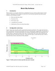
1 Introduction<br />
<strong>Rapid</strong> Drawdown <strong>with</strong> Multi-Stage<br />
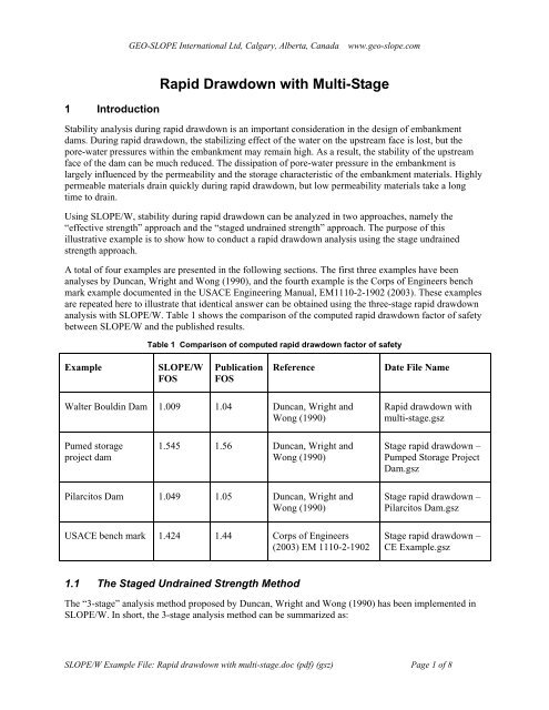
Stability analysis during rapid <strong>drawdown</strong> is an important consideration in the design of embankment<br />
dams. During rapid <strong>drawdown</strong>, the stabilizing effect of the water on the upstream face is lost, but the<br />
pore-water pressures <strong>with</strong>in the embankment may remain high. As a result, the stability of the upstream<br />
face of the dam can be much reduced. The dissipation of pore-water pressure in the embankment is<br />
largely influenced by the permeability and the storage characteristic of the embankment materials. Highly<br />
permeable materials drain quickly during rapid <strong>drawdown</strong>, but low permeability materials take a long<br />
time to drain.<br />
Using <strong>SLOPE</strong>/W, stability during rapid <strong>drawdown</strong> can be analyzed in two approaches, namely the<br />
“effective strength” approach and the “<strong>stage</strong>d undrained strength” approach. The purpose of this<br />
illustrative example is to show how to conduct a rapid <strong>drawdown</strong> analysis using the <strong>stage</strong> undrained<br />
strength approach.<br />
A total of four examples are presented in the following sections. The first three examples have been<br />
analyses by Duncan, Wright and Wong (1990), and the fourth example is the Corps of Engineers bench<br />
mark example documented in the USACE Engineering Manual, EM1110-2-1902 (2003). These examples<br />
are repeated here to illustrate that identical answer can be obtained using the three-<strong>stage</strong> rapid <strong>drawdown</strong><br />
analysis <strong>with</strong> <strong>SLOPE</strong>/W. Table 1 shows the comparison of the computed rapid <strong>drawdown</strong> factor of safety<br />
between <strong>SLOPE</strong>/W and the published results.<br />
Table 1 Comparison of computed rapid <strong>drawdown</strong> factor of safety<br />
Example<br />
<strong>SLOPE</strong>/W<br />
FOS<br />
Publication<br />
FOS<br />
Reference<br />
Date File Name<br />
Walter Bouldin Dam 1.009 1.04 Duncan, Wright and<br />
Wong (1990)<br />
<strong>Rapid</strong> <strong>drawdown</strong> <strong>with</strong><br />
<strong>multi</strong>-<strong>stage</strong>.gsz<br />
Pumed storage<br />
project dam<br />
1.545 1.56 Duncan, Wright and<br />
Wong (1990)<br />
Stage rapid <strong>drawdown</strong> –<br />
Pumped Storage Project<br />
Dam.gsz<br />
Pilarcitos Dam 1.049 1.05 Duncan, Wright and<br />
Wong (1990)<br />
USACE bench mark 1.424 1.44 Corps of Engineers<br />
(2003) EM 1110-2-1902<br />
Stage rapid <strong>drawdown</strong> –<br />
Pilarcitos Dam.gsz<br />
Stage rapid <strong>drawdown</strong> –<br />
CE Example.gsz<br />
1.1 The Staged Undrained Strength Method<br />
The “3-<strong>stage</strong>” analysis method proposed by Duncan, Wright and Wong (1990) has been implemented in<br />
<strong>SLOPE</strong>/W. In short, the 3-<strong>stage</strong> analysis method can be summarized as:<br />
<strong>SLOPE</strong>/W Example File: <strong>Rapid</strong> <strong>drawdown</strong> <strong>with</strong> <strong>multi</strong>-<strong>stage</strong>.doc (<strong>pdf</strong>) (gsz) Page 1 of 8
<strong>GEO</strong>-<strong>SLOPE</strong> <strong>International</strong> <strong>Ltd</strong>, Calgary, Alberta, Canada www.geo-slope.com<br />
The first <strong>stage</strong> involves the stability analysis of the embankment before <strong>drawdown</strong> when the water level is<br />
high and the pore-water pressure in the materials is at steady state condition. Both the effective normal<br />
stress and shear stress along the slip surface are used to determine the undrained shear strength for<br />
materials that do not drain freely.<br />
The second <strong>stage</strong> involves the stability analysis of the embankment after <strong>drawdown</strong> when the water level<br />
is low and the pore-water pressure in the materials is at steady state condition. The effective normal stress<br />
obtained from <strong>stage</strong> two, together <strong>with</strong> the effective strength parameters, are used to compute the drained<br />
strength along the slip surface.<br />
Both the drained and undrained strength at the slice base along the slip surface are compared, and the<br />
smaller strength is chosen as the computed shear strength to be used in the third <strong>stage</strong>. This is needed in<br />
order to avoid using undrained strengths higher than drained strengths which cannot be mobilized if<br />
cavitation or drainage occurs (Duncan, Wright and Wong (1990).<br />
The third <strong>stage</strong> involves the stability analysis using the computed shear strength and the final <strong>drawdown</strong><br />
water level. The computed factor of safety from the first and second <strong>stage</strong>s are ignored, and only the<br />
factor of safety computed from the third <strong>stage</strong> analysis is used to represent the stability after rapid<br />
<strong>drawdown</strong>.<br />
To use the <strong>stage</strong>d rapid <strong>drawdown</strong> method in <strong>SLOPE</strong>/W, the following must be specified:<br />
• A Mohr-Coulomb soil strength model<br />
• Effective c’ and φ’ parameters<br />
• Total c and φ parameters for non-freeely drained material<br />
• A piezometric line pore-water pressure condition<br />
• The positions of the piezometric lines before rapid <strong>drawdown</strong><br />
• The amount of <strong>drawdown</strong><br />
1.2 Example 1 – The Walter Bouldin Dam<br />
The Walter Bouldin dam failed on February 10, 1975 during an extremely rapid <strong>drawdown</strong> of 32 feet in<br />
5.5 hours that occurred as a result of a piping failure in another section of the dam. The dam is a rolled<br />
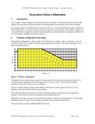
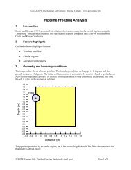
earthfill embankment. As shown in Figure 1, the dam is approximately 60 feet high. The lower portion of<br />
the dam is clayey sandy gravel that was not involved in the slide. Overlaying the gravel are a layer of<br />
clay, a zone of silt and a clayey silty sand layer that blankets the slope. The upper portion of the upstream<br />
slope is blanketed <strong>with</strong> riprap. The upstream slope is 2 on 1 above Elevation 245 and 2.5 on 1 below.<br />
<strong>SLOPE</strong>/W Example File: <strong>Rapid</strong> <strong>drawdown</strong> <strong>with</strong> <strong>multi</strong>-<strong>stage</strong>.doc (<strong>pdf</strong>) (gsz) Page 2 of 8
<strong>GEO</strong>-<strong>SLOPE</strong> <strong>International</strong> <strong>Ltd</strong>, Calgary, Alberta, Canada www.geo-slope.com<br />
Elevation (feet)<br />
280<br />
270<br />
260<br />
250<br />
240<br />
230<br />
220<br />
210<br />
Before Drawdown - El. 252 ft<br />
After - El. 220 ft<br />
200<br />
0 20 40 60 80 100 120 140 160 180 200 220<br />
Figure 1 The Geometry of the Walter Bouldin Dam<br />
Distance (feet)<br />
Figure 2 shows the slip surface and the <strong>SLOPE</strong>/W computed factor of safety using the 3-<strong>stage</strong> undrained<br />
strength method. The factor of safety is 1.009, which is essentially the same as the factor of safety<br />
obtained by Duncan, Wright and Wong (1990).<br />
Figure 2 <strong>SLOPE</strong>/W Computed Factor of Safety Using the 3-Stage Undrained Strength Method<br />
<strong>SLOPE</strong>/W Example File: <strong>Rapid</strong> <strong>drawdown</strong> <strong>with</strong> <strong>multi</strong>-<strong>stage</strong>.doc (<strong>pdf</strong>) (gsz) Page 3 of 8
<strong>GEO</strong>-<strong>SLOPE</strong> <strong>International</strong> <strong>Ltd</strong>, Calgary, Alberta, Canada www.geo-slope.com<br />
1.3 Example 2 – The Pumped Storage Project Dam<br />
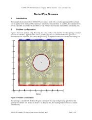
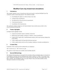
The geometry of the Pumped Storage Project Dam is shown in Figure 3. The dam is about 300 feet high.<br />
The embankment has a densely compacted silty clay core. The lower portion of the upstream slope is a<br />
random zone <strong>with</strong> the same strength properties as the core. The upper portion of the upstream slope and<br />
the downstream slope is free draining rockfill.<br />
The before <strong>drawdown</strong> water level is at 545, and the after <strong>drawdown</strong> water level is at 380, which is the<br />
elevation of the bench at the mid-height of the embankment. The <strong>drawdown</strong> results in complete<br />
dewatering of the upstream rockfill shell and a portion of the filter layer beneath the shell.<br />
700<br />
650<br />
Elevation (feet)<br />
600<br />
550<br />
500<br />
450<br />
400<br />
Before Drawdown El = 545<br />
Before Drawdown El = 380<br />
350<br />
300<br />
250<br />
0.0 0.1 0.2 0.3 0.4 0.5 0.6 0.7 0.8 0.9 1.0 1.1 1.2 1.3 1.4 1.5 1.6 1.7 1.8<br />
Distance (feet) (x 1000)<br />
Figure 3 The Geometry of the Pumped Storage Project Dam<br />
Figure 4 shows the slip surface and the <strong>SLOPE</strong>/W computed factor of safety using the 3-<strong>stage</strong> undrained<br />
strength method. The factor of safety is 1.545, which is almost identical to the factor of safety obtained<br />
by Duncan, Wright and Wong (1990).<br />
Figure 4 <strong>SLOPE</strong>/W Computed Factor of Safety Using the 3 Stage Undrained Strength Method<br />
<strong>SLOPE</strong>/W Example File: <strong>Rapid</strong> <strong>drawdown</strong> <strong>with</strong> <strong>multi</strong>-<strong>stage</strong>.doc (<strong>pdf</strong>) (gsz) Page 4 of 8
<strong>GEO</strong>-<strong>SLOPE</strong> <strong>International</strong> <strong>Ltd</strong>, Calgary, Alberta, Canada www.geo-slope.com<br />
1.4 Example 3 – The Pilarcitos Dam<br />
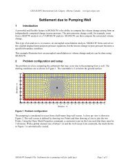
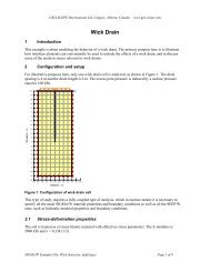
The Pilarcitos Dam is a homogeneous rolled earthfill embankment. The crest of the dam is about 78 feet<br />
above the upstream toe, as shown in Figure 5. The embankment failed when the water level was lowered<br />
from elevation 692 to 657 between Oct 7 and November 19, 1969.<br />
The material comprising the embankment is classified as a sandy clay (CL) <strong>with</strong> 60 to 70 percent passing<br />
the number 200 sieve and a saturated hydraulic conductivity of about 4x10 -6 m/s. The liquid limit is 45<br />
percent and the plastic limit is 23 percent. The effective and total strength parameters used in the analysis<br />
are:<br />
γ soil = 135 pcf,<br />
c ’ = 0 psf,<br />
φ ’ = 45 degrees,<br />
c T = 60 psf,<br />
φ T = 23 degrees<br />
720<br />
Elevation (feet)<br />
670<br />
Before <strong>drawdown</strong> El. 692 ft<br />
After <strong>drawdown</strong> El. 657 ft<br />
620<br />
0 100 200 300<br />
Figure 5 The Geometry of the Pilarcitos Dam<br />
Distance (feet)<br />
Figure 6 shows the slip surface and the <strong>SLOPE</strong>/W computed factor of safety using the 3-<strong>stage</strong> undrained<br />
strength method. The factor of safety is 1.049, which is essentially the same as the factor of safety<br />
obtained by Duncan, Wright and Wong (1990).<br />
<strong>SLOPE</strong>/W Example File: <strong>Rapid</strong> <strong>drawdown</strong> <strong>with</strong> <strong>multi</strong>-<strong>stage</strong>.doc (<strong>pdf</strong>) (gsz) Page 5 of 8
<strong>GEO</strong>-<strong>SLOPE</strong> <strong>International</strong> <strong>Ltd</strong>, Calgary, Alberta, Canada www.geo-slope.com<br />
Figure 6 <strong>SLOPE</strong>/W Computed Factor of Safety Using the 3 Stage Undrained Strength Method<br />
1.5 Example 4 – The USACE Benchmark Example<br />
Example 4 is the benchmark example used by the U.S. Army Corps of Engineers (2003) in the Appendix<br />
G of the Engineering Manual – EM 1110-2-1902. It is a simple homogenous embankment. The material<br />
properties are:<br />
γ soil = 135 pcf<br />
c ’ = 0 psf<br />
φ ’ = 30 degrees<br />
c T = 1200 psf<br />
φ T = 16 degrees<br />
The slip surface is established by a center located at x=169.5 feet, y =210 feet and a radius of 210 feet.<br />
Drawdown is from a maximum water level of 103 feet to a minimum level of 24 feet. The upstream slope<br />
is 3 to 1 up to elevation 74 and 2.5 to 1 above elevation 74.<br />
<strong>SLOPE</strong>/W Example File: <strong>Rapid</strong> <strong>drawdown</strong> <strong>with</strong> <strong>multi</strong>-<strong>stage</strong>.doc (<strong>pdf</strong>) (gsz) Page 6 of 8
<strong>GEO</strong>-<strong>SLOPE</strong> <strong>International</strong> <strong>Ltd</strong>, Calgary, Alberta, Canada www.geo-slope.com<br />
Figure 7 The Geometry of the USACE Bench Mark Example<br />
Figure 8 shows the slip surface and the <strong>SLOPE</strong>/W computed factor of safety using the 3-<strong>stage</strong> undrained<br />
strength method. The factor of safety is 1.424, which is almost identical to the factor of safety as<br />
presented in the Corps of Engineers (2003) engineering manual.<br />
Figure 8 <strong>SLOPE</strong>/W Computed Factor of Safety Using the 3 Stage Undrained Strength Method<br />
<strong>SLOPE</strong>/W Example File: <strong>Rapid</strong> <strong>drawdown</strong> <strong>with</strong> <strong>multi</strong>-<strong>stage</strong>.doc (<strong>pdf</strong>) (gsz) Page 7 of 8
1.6 Discussions<br />
<strong>GEO</strong>-<strong>SLOPE</strong> <strong>International</strong> <strong>Ltd</strong>, Calgary, Alberta, Canada www.geo-slope.com<br />
As illustrated in the above three examples, it is evident that the Duncan, Wright and Wong’s 3-Stage has<br />
been implemented correctly in <strong>SLOPE</strong>/W. The computed factors of safety in all three cases are identical<br />
to those presented by Duncan, Wright and Wong (1990) and the USACE Engineering Manual (2003).<br />
The 3-Stage method seems to provide a reasonable evaluation of the stability during rapid <strong>drawdown</strong>. The<br />
approach avoids the extra work of evaluating the pore-water pressure conditions in the embankment dam<br />
by using the undrained strengths. However, the hydraulic properties of the materials, such as<br />
permeability, cannot be considered, the element of time is missing, and the total strength parameters are<br />
used.<br />
References<br />
Corps of Engineers (1970) “Engineering and Design – Stability of Earth and Rock Fill Dams”.<br />
Engineering Manual, EM 1110-2-1902. Department of the U.S Army Corps of Engineers.<br />
Corps of Engineers (2003) “Appendix G - Procedures and Examples for <strong>Rapid</strong> Drawdown”. Engineering<br />
Manual, EM 1110-2-1902. Department of the U.S Army Corps of Engineers.<br />
Duncan, J.M.,Wright S.G. and Wong, K.S. (1990). “Slope Stability during <strong>Rapid</strong> Drawdown”.<br />
Proceedings of H. Bolton Seed Memorial Symposium. Vol. 2.<br />
Lowe, J and Karafiath, L., (1960) “Stability of Earth Dams Upon Drawdown”. Proceedings of 1 st PanAm<br />
Conference on Soil Mechanic and Foundation Engineering. Mexico City, Vol 2.<br />
<strong>SLOPE</strong>/W Example File: <strong>Rapid</strong> <strong>drawdown</strong> <strong>with</strong> <strong>multi</strong>-<strong>stage</strong>.doc (<strong>pdf</strong>) (gsz) Page 8 of 8