Belimo VRD2 - TROX
Belimo VRD2 - TROX Belimo VRD2 - TROX
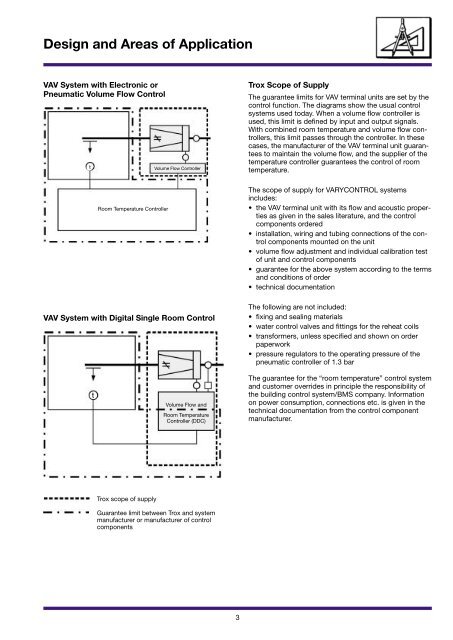
Design and Areas of Application VAV System with Electronic or Pneumatic Volume Flow Control t VAV System with Digital Single Room Control t Room Temperature Controller Trox scope of supply Volume Flow Controller Volume Flow and Room Temperature Controller (DDC) Guarantee limit between Trox and system manufacturer or manufacturer of control components 3 Trox Scope of Supply The guarantee limits for VAV terminal units are set by the control function. The diagrams show the usual control systems used today. When a volume flow controller is used, this limit is defined by input and output signals. With combined room temperature and volume flow controllers, this limit passes through the controller. In these cases, the manufacturer of the VAV terminal unit guarantees to maintain the volume flow, and the supplier of the temperature controller guarantees the control of room temperature. The scope of supply for VARYCONTROL systems includes: • the VAV terminal unit with its flow and acoustic properties as given in the sales literature, and the control components ordered • installation, wiring and tubing connections of the control components mounted on the unit • volume flow adjustment and individual calibration test of unit and control components • guarantee for the above system according to the terms and conditions of order • technical documentation The following are not included: • fixing and sealing materials • water control valves and fittings for the reheat coils • transformers, unless specified and shown on order paperwork • pressure regulators to the operating pressure of the pneumatic controller of 1.3 bar The guarantee for the “room temperature” control system and customer overrides in principle the responsibility of the building control system/BMS company. Information on power consumption, connections etc. is given in the technical documentation from the control component manufacturer.
Room Temperature Control Circuit Set point Effect on room temperature Volume Flow Control Circuit 3 2 Control deviation Variable volume flow ∆p w 5 M 4 1 Volume flow controller 2 Differential pressure sensor 3 Control damper blade 4 Differential pressure transducer 5 Actuator 6 Room temperature controller Room temperature controller Volume flow controller 1 6 Energy requirement Design and Areas of Application 4 Description of Function “Room Temperature” Control Circuit In a VAV system, the volume flow control circuit is governed by a room temperature-dependent signal. The room temperature is measured with a temperature sensor. The room temperature controller compares the actual value with the set value and provides an output signal corresponding to the resulting energy requirement which is used as a set point signal for the volume flow controller. If the room temperature rises, the cooling effect is increased by increasing the volume flow (with cold supply air) and the room temperature held at its set point. Volume Flow Cascade Control Circuit The volume flow control has a closed control circuit: measurement – comparison – adjustment. As volume measurement accuracy is essential for quality, an optimised differential pressure sensor was developed for the Trox VARYCONTROL VAV terminal units. Differential pressures are measured at the inlet to the multi point flow grid. The particular arrangement of the measurement points gives an amplifica-tion of the dynamic pressure as a mean value. The differential pressure thus measured is a function of the volume flow and is converted into an electrical or pneumatic signal by a transducer. The volume flow controller determines the volume flow from the transducer signal. Depending on the control deviation between actual and set values, the control damper blade is adjusted by the actuator until the actual value and set point are equal (P or Pl control depending on controller type). The volume flow controller maintains a constant volume flow over the specified pressure range within controller-dependent tolerances. Duct pressure fluctuations cannot therefore have a disruptive effect on the room temperature control.
- Page 1 and 2: VARYCONTROL Reference List Design a
- Page 3 and 4: Reference list VARYCONTROL KADEWE-B
- Page 5: TVZ · TVA TVM TVR TVRK TVJ/TVT Des
- Page 9 and 10: Single Duct System with Reheat Coil
- Page 11 and 12: Explanation of Order Codes The cont
- Page 13 and 14: Installation 1 Contents Subject Pag
- Page 15 and 16: Installation TVZ . TVA Delivery and
- Page 17 and 18: Installation TVJ with TX TVJ/TVT wi
- Page 19 and 20: Disengaging the Drive Function Test
- Page 21 and 22: TVRK Volume Flow Controller and Tra
- Page 23 and 24: Removing tubes Maintenance 1 Specia
- Page 25 and 26: VRD2 VRD2 Tube connection for trans
- Page 27 and 28: Pressure Independent Control Charac
- Page 29 and 30: Volume Flow Ranges TVZ, TVA, TVR, T
- Page 31 and 32: Volume Flow Ranges TVM Size V · mi
- Page 33 and 34: Override Controls RT Controller Ope
- Page 35 and 36: Function Test Fault Finding Check C
- Page 37 and 38: VRP � � � � Characteristic
- Page 39 and 40: VRP Adjustment Knobs � � �
- Page 41 and 42: Volume Flow Control Tolerances 1) V
- Page 43 and 44: Terminal Connections Plug connectio
- Page 45 and 46: Function Test Fault Finding Check C
- Page 47 and 48: VRP-STP Area of Application ��
- Page 49 and 50: Room Pressure Ranges Differential p
- Page 51 and 52: Parallel Differential Pressure Cont
- Page 53 and 54: Belimo VFP 1 Contents Subject Page
- Page 55 and 56: Belimo VFP Zero Point Adjustment
Design and Areas of Application<br />
VAV System with Electronic or<br />
Pneumatic Volume Flow Control<br />
t<br />
VAV System with Digital Single Room Control<br />
t<br />
Room Temperature Controller<br />
Trox scope of supply<br />
Volume Flow Controller<br />
Volume Flow and<br />
Room Temperature<br />
Controller (DDC)<br />
Guarantee limit between Trox and system<br />
manufacturer or manufacturer of control<br />
components<br />
3<br />
Trox Scope of Supply<br />
The guarantee limits for VAV terminal units are set by the<br />
control function. The diagrams show the usual control<br />
systems used today. When a volume flow controller is<br />
used, this limit is defined by input and output signals.<br />
With combined room temperature and volume flow controllers,<br />
this limit passes through the controller. In these<br />
cases, the manufacturer of the VAV terminal unit guarantees<br />
to maintain the volume flow, and the supplier of the<br />
temperature controller guarantees the control of room<br />
temperature.<br />
The scope of supply for VARYCONTROL systems<br />
includes:<br />
• the VAV terminal unit with its flow and acoustic properties<br />
as given in the sales literature, and the control<br />
components ordered<br />
• installation, wiring and tubing connections of the control<br />
components mounted on the unit<br />
• volume flow adjustment and individual calibration test<br />
of unit and control components<br />
• guarantee for the above system according to the terms<br />
and conditions of order<br />
• technical documentation<br />
The following are not included:<br />
• fixing and sealing materials<br />
• water control valves and fittings for the reheat coils<br />
• transformers, unless specified and shown on order<br />
paperwork<br />
• pressure regulators to the operating pressure of the<br />
pneumatic controller of 1.3 bar<br />
The guarantee for the “room temperature” control system<br />
and customer overrides in principle the responsibility of<br />
the building control system/BMS company. Information<br />
on power consumption, connections etc. is given in the<br />
technical documentation from the control component<br />
manufacturer.


