Belimo VRD2 - TROX
Belimo VRD2 - TROX
Belimo VRD2 - TROX

You also want an ePaper? Increase the reach of your titles
YUMPU automatically turns print PDFs into web optimized ePapers that Google loves.
Commissioning<br />
C-Values TVZ, TVS, TVR, TVM and TVA Transducer Curve<br />
Size TVZ/TVR/TVS TVM-cold TVM-tot. TVA<br />
10 6.11) 12 9.7 9.7 16.8 9.0<br />
16 15.9 15.9 29.1 15.2<br />
20 25.5 25.5 44 24.2<br />
25 39 39 61 38<br />
31 65 63<br />
40 106 103<br />
1) TVR only<br />
C-Values TVJ/TVT<br />
B x H<br />
mm<br />
C<br />
200 x 100 14.8<br />
300 x 100 21.2<br />
400 x 100 28.8<br />
500 x 100 35<br />
600 x 100 44<br />
200 x 200 30<br />
300 x 200 45<br />
400 x 200 60<br />
500 x 200 75<br />
600 x 200 90<br />
700 x 200 107<br />
800 x 200 120<br />
300 x 300 75<br />
400 x 300 100<br />
500 x 300 137<br />
600 x 300 147<br />
700 x 300 174<br />
800 x 300 207<br />
900 x 300 228<br />
1000 x 300 254<br />
B x H<br />
mm<br />
C<br />
400 x 400 146<br />
500 x 400 183<br />
600 x 400 212<br />
700 x 400 239<br />
800 x 400 281<br />
900 x 400 320<br />
1000 x 400 359<br />
500 x 500 207<br />
600 x 500 234<br />
700 x 500 284<br />
800 x 500 318<br />
900 x 500 361<br />
1000 x 500 409<br />
600 x 600 297<br />
700 x 600 344<br />
800 x 600 396<br />
900 x 600 461<br />
1000 x 600 508<br />
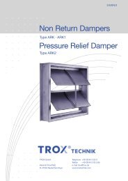
Measuring the Effectiv Pressure ∆p e<br />
1<br />
1 Remove test point cap and replace after<br />
measurement<br />
2 Manometer<br />
2<br />
B x H<br />
mm<br />
C<br />
700 x 700 415<br />
800 x 700 469<br />
900 x 700 535<br />
1000 x 700 597<br />
800 x 800 543<br />
900 x 800 636<br />
1000 x 800 681<br />
900 x 900 720<br />
1000 x 900 786<br />
1000 x 1000 904<br />
3<br />
The transducers are calibrated in the Trox works such<br />
that the transducer output signal shown on the curve<br />
agrees with the actual volume flows. This setting is<br />
sealed. If the transducers are tested, the differential<br />
pressure must be measured at the differential pressure<br />
sensor. If the measuring lines contain T-pieces, a manometer<br />
can be connected. If the transducer has no T-piece<br />
at the effectiv pressure sensor, parallel measurement is<br />
not possible. In this case, the actuator must be locked in<br />
position (release wiring, program manual operation etc).<br />
After measuring the transducer output voltage, the tubes<br />
are carefully removed from the transducer connections<br />
and the effectiv pressure measured. The volume flow is<br />
calculated according to the formula below.<br />
V · l/s = C . ∆p e<br />
V · m 3 /h =C . ∆p e . 3.6<br />
in l/s<br />
in m 3/h<br />
V ·<br />
: volume flow<br />
�pe : measured effectiv pressure in Pa<br />
C : constant for air density � = 1.2 kg/m3 The accuracy for the measurement is ± 7 % (for TVM total<br />
± 12 %).<br />
If the minimum requirements given in the leaflets for the<br />
flow conditions are not observed, this tolerance will be<br />
greater.<br />
Volume Flow Adjustment<br />
The volume flow limit value can be changed, depending<br />
on controller type, by adjusting setting knobs with percentage<br />
scales, manual operation devices or by computer.<br />
For analogue controllers, the adjustment accuracy<br />
can be increased if the transducer signal is measured<br />
and the volume flow set according to the voltage curve.<br />
Ensure that the controller will actually control at<br />
V · min or V · max and that the system pressure is adequate.<br />
The DDC controller parameters are reprogrammed using<br />
a laptop P.C. or through the network via the central computer.