

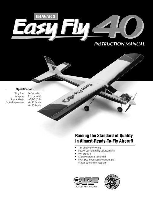
instruction manual - Hangar 9
instruction manual - Hangar 9
instruction manual - Hangar 9

You also want an ePaper? Increase the reach of your titles
YUMPU automatically turns print PDFs into web optimized ePapers that Google loves.
TM<br />
HANGAR 9<br />
INSTRUCTION MANUAL<br />
Specifications<br />
Wing Span<br />
Wing Area<br />
Approx. Weight<br />
Engine Requirements<br />
.64-3/4 inches<br />
.712-1/4 inch2<br />
.4-3/4-5 1/2 lbs.<br />
.40-.46 2-cycle<br />
.40-.50 4-cycle<br />
Raising the Standard of Quality<br />
in Almost-Ready-To-Fly Aircraft<br />
• True UltraCote covering<br />
• Positive self-righting flight characteristics<br />
• 90% pre-built<br />
• Extensive hardware kit included<br />
• Break away motor mount prevents engine<br />
damage during minor nose-overs<br />
90 %<br />
PRE-BUILT<br />
ALMOST READY-TO-FLY
TICKET TO FLY<br />
R/C Pilot Program<br />
The Total Training Package<br />
Congratulations on your selection of the <strong>Hangar</strong> 9 Easy Fly<br />
40! Your kit comes complete with the “TICKET TO FLY R/C<br />
Pilot Program,” a detailed video <strong>instruction</strong> guide designed<br />
to help beginners become successful pilots.<br />
This video guides you through every step of the learning<br />
process — from building tricks and tips through your first solo flights. The<br />
video shows in-depth procedures on radio setup, trimming the plane, and<br />
breaking-in and tuning your engine. It covers the basic flight concepts you<br />
need to know, like takeoffs, landings and, most importantly, how to find and<br />
work with a qualified instructor. You’ll find out just what to expect when<br />
you arrive at the flying field… before you even get there.<br />
When you use the video in conjunction with the complete, photo-illustrated<br />
<strong>instruction</strong> <strong>manual</strong>, you’ll gain the confidence and ability to successfully<br />
meet the challenge of R/C flight. This video is an invaluable teaching aid<br />
which will shorten the time it takes to properly learn to operate and fly the<br />
Easy Fly 40.<br />
Good Luck and Good Flying!<br />
TM<br />
2
Table Of Contents<br />
Introduction 3<br />
Contents Of Kit 4<br />
Equipment Required 5<br />
Tools And Supplies Required 5<br />
Field Equipment Required 6<br />
Optional Field Equipment 7<br />
Section 1: Assembling The Wings 8<br />
Section 2: Joining The Wing Halves 9<br />
Section 3: Hinging The Rudder And Elevator 12<br />
Section 4: Installing The Aileron Servo Trays 13<br />
Section 5: Assembling The Fuselage 16<br />
Section 6: Installing The Nose Gear 17<br />
Section 7: Installing The Wing Dowels 18<br />
Section 8: Assembling The Fuel Tank 19<br />
Section 9: Installing The Fuel Tank 21<br />
Section 10: Installing The Control Horns 22<br />
Section 11: Installing The Horizontal & Vertical Stabilizers 24<br />
Section 12: Installing The Engine 26<br />
Section 13: Installing The Radio 29<br />
Section 14: Installing The Linkages 32<br />
Section 15: Setting Up The Radio 38<br />
Section 16: Balancing The Model 39<br />
Pre-Flight Check 40<br />
Pre-Flight At The Field 41<br />
Flight Instructions 42<br />
AMA Safety Codes 43<br />
Glossary 44<br />
3
Introduction<br />
Congratulations!<br />
You are the proud owner of the highest quality almost-ready-to-fly (ARF) sport trainer available. The Easy Fly<br />
40 is professionally built and pre-covered by craftsmen using genuine UltraCote ® covering. The positive selfrighting<br />
flight characteristics and excellent slow-speed handling make the Easy Fly 40 one of the easiest-to-fly<br />
airplanes available. Beyond its positive, gentle flight mannerisms, the Easy Fly 40 also offers outstanding<br />
sport aerobatic capabilities. Loops, rolls, sustained inverted flight, and even outside maneuvers are all well<br />
within its flight envelope.<br />
In order for you to get the best performance and most enjoyment from your Easy Fly 40, it is important to<br />
carefully read and follow this <strong>manual</strong>. If you’re a first-time flier, we strongly suggest that you seek qualified<br />
help during your first flights. Your local hobby shop will be able to put you in touch with qualified pilots and a<br />
local club.<br />
ULTRACOTE®<br />
UltraCote is a registered trademark of Carl<br />
Goldberg Models<br />
The Easy Fly 40 is professionally built and<br />
pre-covered by craftsmen using genuine UltraCote®<br />
covering. UltraCote is completely reparable and can<br />
be found at your local hobby shop.<br />
Note: Due to temperature changes during shipping, the covering on your Easy Fly may be slightly wrinkled.<br />
The careful use of a heat gun or iron is recommended to shrink the UltraCote ® until its taut.<br />
Warning<br />
An R/C aircraft is not a toy! If misused, it can cause serious bodily harm and damage to property. Fly only in<br />
open areas, preferably AMA (Academy of Model Aeronautics) approved flying sites, and have an experienced<br />
modeler/pilot preflight your aircraft before its first flight and perform the aircraft’s first test flights. Please<br />
follow all <strong>instruction</strong>s included with your radio and engine. We cannot stress strongly enough the importance<br />
of having an experienced pilot preflight your aircraft and be present during your first test flights!<br />
4
Contents Of Kit<br />
B<br />
E<br />
C<br />
D<br />
A<br />
A. Fuselage (#HAN1401)<br />
B. Right wing half with aileron (#HAN1402)<br />
C. Left wing half with aileron (#HAN1402)<br />
D. Vertical stabilizer with rudder (#HAN1403)<br />
E. Horizontal stabilizer with elevator (#HAN1404)<br />
1<br />
7<br />
11<br />
3<br />
2<br />
4<br />
6<br />
9<br />
5<br />
8<br />
1. Pushrods<br />
2. Aileron servo mounts (2)<br />
3. Main landing gear<br />
4. Nose landing gear<br />
5. Spinner<br />
6. Motor mounts and hardware<br />
7. Wheels (3)<br />
8. Fuel tank and hardware<br />
9. Rubber bands (8)<br />
10. Control horns<br />
11. Wing joiner<br />
10<br />
5
Equipment Required<br />
R/C Radio System<br />
4 Channels (minimum)<br />
4 Standard Servos<br />
Standard 450-650 mAh Battery<br />
R/C Engine<br />
.40-.45 2-Cycle with Muffler<br />
Recommended JR Systems<br />
JR F400 FM<br />
JR XP642<br />
JR XP783<br />
JR XP8103<br />
Recommended Thunder Tiger Engine<br />
GP .42 with Muffler<br />
R/C Aircraft Propeller<br />
10-6 Prop with a .40-.46 Size Engine<br />
Tools And Supplies Required<br />
Adhesives<br />
CA (cyanoacrylate) Glue (instant/thin and medium viscosity)<br />
CA Remover (dissolve)<br />
5-Minute Epoxy<br />
30-Minute Epoxy<br />
Tools<br />
Clips (e.g. clothespins, binder clips)<br />
Cloth<br />
Drill and Assorted Drill Bits<br />
Heat Gun<br />
Heat Iron<br />
Hobby Knife<br />
Masking Tape<br />
Needle Nose Pliers<br />
Paper Towels<br />
Pencil<br />
#1 and #2 Phillips Screwdrivers<br />
Rubbing Alcohol<br />
Ruler (straight edge)<br />
Sandpaper<br />
Scissors<br />
Straight Screwdriver<br />
Thread Lock (e.g., Loc Tite Blue)<br />
Toothpicks<br />
90-Degree Triangle<br />
Wax Paper<br />
Z-Bender Pliers<br />
6
Field Equipment Required<br />
HAN3000 – 2-cycle Performance Plug MDC101 Glow Driver Model Airplane Fuel<br />
HAN 3005 – Extra Life Sport Plug<br />
HAN104 12V Super Starter HAN102 12V Battery HAN118 Fuel Pump<br />
HAN2510 Glow Plug Wrench<br />
7
Optional Field Equipment<br />
Extra Propellers Flight Box Power Panel<br />
Prop Wrench Miscellaneous Tools Paper Towels<br />
#64 Rubber Bands After Run Oil Extra Glow Plugs<br />
8
Section 1: Assembling The Wings<br />
Parts Needed<br />
Left Wing Panel with Aileron and Hinges<br />
Right Wing Panel with Aileron and Hinges<br />
Tools Needed<br />
CA Remover<br />
30-Minute Epoxy<br />
Thin Instant CA Glue<br />
Paper Towels<br />
Rubbing Alcohol<br />
Toothpicks<br />
❑ 1.<br />
Carefully remove the aileron from the right wing panel.<br />
Note where the hinges and the aileron torque rod fit into<br />
the aileron.<br />
❑ 5.<br />
Wipe off any excess epoxy using a paper towel and<br />
rubbing alcohol.<br />
❑ 2.<br />
Mix a small amount of 30-minute epoxy, carefully<br />
following the <strong>instruction</strong>s included with the epoxy.<br />
❑ 6.<br />
Deflect the aileron and apply a small amount of thin CA<br />
glue to each hinge. Make sure that the CA glue<br />
penetrates into the aileron and wing while maintaining a<br />
1/16” aileron gap.<br />
❑ 3.<br />
Using a toothpick, apply epoxy into the ailerons’ torque<br />
rod hole. Fill the hole 1/2 full.<br />
❑ 7.<br />
Wipe off any excess CA glue using CA remover and a<br />
paper towel.<br />
❑ 4.<br />
Replace the aileron on the right wing half. Make sure<br />
the hinges slide in place and the aileron torque rod<br />
inserts into its respective hole in the aileron. The gap<br />
between aileron and wing should be a constant 1/16”.<br />
❑ 8. Repeat this process for the left wing (Steps 1-7).<br />
Note:<br />
After the CA has dried completely, check to ensure that<br />
the hinges are secure by pulling firmly on the ailerons.<br />
Important:<br />
The ailerons are fitted in place but not glued in. They<br />
must be correctly glued prior to flying.<br />
9
Section 2: Joining The Wing Halves<br />
Parts Needed<br />
Aileron Servo Mounts (2)<br />
Dihedral Brace<br />
Left Wing Half from Section 1<br />
Right Wing Half from Section 1<br />
Standard Servo (1)<br />
Tools Needed<br />
30-Minute Epoxy<br />
Hobby Knife<br />
Masking Tape<br />
Paper Towels<br />
Pencil<br />
Rubbing Alcohol<br />
Ruler<br />
Wax Paper<br />
❑ 1.<br />
Using a pencil, mark both wing roots (the exposed<br />
wood end of the wing halves) as shown.<br />
❑ 2. Using a hobby knife, carefully cut out the marked<br />
section.<br />
Important:<br />
Do not cut into hard wood wing joiner section.<br />
10
Section 2: Joining The Wing Halves<br />
CONTINUED<br />
❑ 3.<br />
Locate the dihedral brace (also called the wing joiner).<br />
Using a ruler and pencil, mark the exact center of the<br />
brace as shown.<br />
❑ 5.<br />
Coat one half of the dihedral brace with epoxy up to the<br />
line. Note the orientation of the V of the dihedral<br />
brace. Install the epoxy-coated side of the dihedral<br />
brace into a wing half up to the line, making sure the V<br />
of the dihedral brace is positioned correctly as shown.<br />
❑ 4.<br />
Mix approximately 2 ounces of 30-minute epoxy. In<br />
this step, be sure to use plenty of epoxy. Using a scrap<br />
piece of wood, smear the epoxy into the wing joiner<br />
cavity of both wings. (Remember, use plenty of epoxy.)<br />
11
Section 2: Joining The Wing Halves<br />
❑ 6.<br />
Apply epoxy to the exposed area (other end) of the<br />
dihedral brace. Uniformly coat both wing roots with<br />
30-minute epoxy.<br />
❑ 7.<br />
CONTINUED<br />
Carefully slide the two wing halves together. Firmly<br />
press the two halves together, allowing the excess<br />
epoxy to run out. Using rubbing alcohol and a paper<br />
towel, clean off the excess epoxy.<br />
Important:<br />
Be sure the wings are pressed firmly together at the<br />
center section. Be sure that the leading and trailing<br />
edges line up properly. Use masking tape as necessary<br />
to hold the wing halves in position.<br />
❑ 8.<br />
Place a 12” x 12” sheet of wax paper on the edge of a<br />
flat table. Place the center section of the wing on the<br />
wax paper with the aileron torque rod hanging off the<br />
edge of the table. Prop up each wing tip 2-1/2 inches<br />
off the table as shown. Books work well for this.<br />
❑ 9.<br />
Wipe off any excess epoxy using rubbing alcohol and<br />
paper towels. Allow the wing to set undisturbed<br />
overnight to dry completely.<br />
12
Section 3: Hinging The Rudder And Elevator<br />
Parts Needed<br />
Horizontal Stabilizer with Elevator and Hinges<br />
Vertical Stabilizer with Rudder and Hinges<br />
Tools Needed<br />
CA Remover<br />
Paper Towels<br />
Thin Instant CA Glue<br />
❑ 1.<br />
Push the elevator and horizontal stabilizer together until<br />
there is a constant 1/16” gap between the two and the<br />
edges are lined up correctly.<br />
❑ 4.<br />
Wipe off any excess CA using CA remover and a paper<br />
towel. Set these assemblies aside for now.<br />
❑ 2.<br />
❑ 3.<br />
Deflect the elevator and apply thin CA glue at the<br />
hinges so that it absorbs both into the stabilizer and the<br />
elevator (4 places).<br />
Using the same technique, hinge the rudder to the<br />
vertical stabilizer.<br />
Note:<br />
After CA has dried completely, check to ensure that the<br />
hinges are secured by pulling firmly on the control<br />
surfaces.<br />
13
Section 4: Installing The Aileron Servo Trays<br />
Parts Needed<br />
Aileron Servo Trays (2)<br />
Wing Center Section Tape<br />
Tools Needed<br />
Clips (e.g., clothespins,<br />
binder clips) (4)<br />
5-Minute Epoxy<br />
Hobby Knife<br />
Masking Tape<br />
Paper Towels<br />
Pencil<br />
Ruler<br />
❑ 1.<br />
Mix a small amount of 5-minute epoxy as per the<br />
<strong>instruction</strong>s included with the epoxy. Remember, once<br />
this epoxy is mixed, you have only 5 minutes of<br />
working time until it dries.<br />
❑ 4.<br />
Using a ruler, measure the distance on the bottom of<br />
the wing at the center line 5-1/2 inches from the trailing<br />
edge and mark with a pencil.<br />
❑ 2.<br />
Spread a thin layer of epoxy over the entire surface of<br />
one side of an aileron tray.<br />
❑ 5.<br />
Next, measure 3-3/4 inches from the leading edge back<br />
to the center line and mark with a pencil.<br />
❑ 3.<br />
Join the two aileron trays as shown and clamp them<br />
together using four clips. Be sure the two trays are<br />
properly aligned. Wipe off any excess epoxy with a<br />
paper towel and set aside to dry for 15 minutes.<br />
14
Section 4: Installing The Aileron Servo Trays<br />
CONTINUED<br />
❑ 6.<br />
Unclamp the aileron tray when dry and position it on<br />
the center line so the two marks are visible on the<br />
inside of the aileron tray.<br />
❑ 9.<br />
Carefully remove the covering in the aileron tray area.<br />
This is necessary so that the tray will properly adhere to<br />
the wing.<br />
❑ 7.<br />
Carefully trace around the outside of the aileron tray<br />
using a pencil.<br />
❑ 10. Mix a small amount of 5-minute epoxy and spread it<br />
over the entire area of one side of the servo tray.<br />
❑ 8.<br />
Remove the aileron tray. Using a sharp hobby knife,<br />
carefully cut through the plastic covering. Be careful<br />
not to cut into the wood on the line you just made in<br />
Step 7.<br />
15
Section 4: Installing The Aileron Servo Trays<br />
❑ 11. Place the aileron tray, glue side down, on the exposed<br />
wood area on the bottom of the wing and gently press it<br />
into position. Use masking tape if necessary to hold in<br />
position until dry. Allow 15 minutes for the epoxy to<br />
cure.<br />
CONTINUED<br />
❑ 13. Locate the wing center tape (white adhesive-backed<br />
tape) and remove the adhesive backing. Starting at the<br />
edge of the aileron tray, apply the tape around the wing<br />
at the center section, ending at the other side of the<br />
tray. Use a hobby knife to trim the excess length of<br />
tape. Your wing is now complete.<br />
❑ 12. Using a sharp hobby knife, carefully cut out the balsa<br />
wood from the inside section of the aileron tray and<br />
remove.<br />
❑ 14. Locate the small blue decal (square in shape) on the<br />
decal sheet included with your kit. Apply this decal to<br />
the leading edge of the wing to cover the wing center<br />
tape that you have just applied. Press firmly to ensure<br />
that the decal adheres properly to the wing.<br />
16
Section 5: Assembling The Fuselage<br />
Parts Needed<br />
Fuselage<br />
Main Landing Gear (2 pcs)<br />
Main Landing Gear Hardware<br />
Wheels (2 pcs)<br />
Wheel Collars with Screws (2 pcs)<br />
Tools Needed<br />
Drill with 1/16” Drill Bit<br />
#1 and #2 Phillips Screwdrivers<br />
Thread Lock<br />
❑ 1.<br />
Locate the main landing gear slot in the bottom of the<br />
fuselage. Position the two landing gear straps across<br />
the slot as shown and drill four 1/16” holes using the<br />
straps as a guide. Remove the straps after all four holes<br />
are drilled.<br />
❑ 3.<br />
Reposition the landing gear straps over the 1/16” hole<br />
you drilled in Step 1. Screw into position with the four<br />
sheet metal screws provided.<br />
❑ 2.<br />
Locate the two main landing gear struts and insert them<br />
into the landing gear slot as shown. Make sure the ends<br />
fit into the holes in the edges of the slot.<br />
❑ 4.<br />
Place the wheels on the ends of the struts and secure<br />
them with the supplied wheel collars. Use thread lock<br />
on the collar screws.<br />
17
Section 6: Installing The Nose Gear<br />
Parts Needed<br />
Nose Gear Wheel (1)<br />
Spring Wheel Collar with Screws (2)<br />
Steering Arm<br />
Tools Needed<br />
#2 Phillips Screwdriver<br />
Thread Lock<br />
❑ 1.<br />
The nose gear mount is pre-assembled onto the front<br />
firewall of the fuselage. Locate the nose gear. On the<br />
straight end, first slide the steering arm onto the nose<br />
gear (note the orientation as shown in the photo). Use<br />
thread lock and a #2 Phillips screwdriver to secure the<br />
steering arm in place. Next, install a collar and secure it<br />
in place with the thread lock and a machine screw. Now<br />
slide the spring into position.<br />
❑ 3.<br />
Attach the nose wheel and hold it in place using a<br />
wheel collar and screw.<br />
❑ 2.<br />
Insert the nose gear assembly from Step 1 into the nose<br />
gear mount (attached to the front of the fuselage). Be<br />
sure the spring stays in position and rests against the<br />
nose gear mount. Install the collar on the top end of the<br />
landing gear flush with the landing gear, and secure it<br />
into position with a screw and the thread lock.<br />
18
Section 7: Installing The Wing Dowels<br />
Parts Needed<br />
Fuselage<br />
Wing Dowels (2)<br />
Tools Needed<br />
CA Remover<br />
Hobby Knife<br />
Paper Towel<br />
Thin Instant CA Glue<br />
❑ 1.<br />
Using a sharp hobby knife, carefully cut the covering<br />
around the four holes as shown, leaving a circle that the<br />
dowel will be pressed into.<br />
❑ 2.<br />
Install the two dowels and position them so that an<br />
equal amount of dowel extends from each side of the<br />
fuselage. Using thin CA glue, apply five drops around<br />
each side of the wing dowel (4 places) where the dowel<br />
touches the fuselage.<br />
❑ 3.<br />
If necessary, use a paper towel and CA remover to wipe<br />
off any excess CA glue.<br />
19
Section 8: Assembling The Fuel Tank<br />
Parts Needed<br />
Clunk (brass fuel pickup)<br />
Copper Tube, Long (vent)<br />
Copper Tube, Short (pickup)<br />
Fuel Line, Small<br />
Fuel Tank<br />
Plastic Cups (2)<br />
Rubber Stopper<br />
3mm Screw and 3mm Nut<br />
Tools Needed<br />
Hobby Knife<br />
#1 Phillips Screwdriver<br />
❑ 1.<br />
Locate the black rubber stopper. Insert the short copper<br />
tube into one of the open holes in the stopper so that an<br />
equal amount of tube extends from each side. This tube<br />
will be the fuel tank pickup tube.<br />
❑ 3.<br />
Slide this tube into the other open hole of the stopper,<br />
as shown.<br />
❑ 2.<br />
Locate the long copper tube and bend it using your<br />
fingers, as shown. This tube will be the fuel tank vent<br />
tube.<br />
❑ 4.<br />
Slide the two white plastic caps over the copper tubes<br />
as shown. Note the orientation of the caps. The small<br />
inside cap and the three “pegs” face away from the<br />
black rubber stopper. The large outside cap and the<br />
“raised center” go away from the black rubber stopper.<br />
20
Section 8: Assembling The Fuel Tank<br />
❑ 5. Locate the small diameter fuel tubing and cut it to 3”<br />
in length. This tubing will be used for the fuel pick-up<br />
inside the fuel tank. Insert the brass clunk into one end<br />
of the fuel tubing.<br />
❑ 7.<br />
CONTINUED<br />
Press the 3mm locknut between the three pegs on the<br />
inside white plastic cap as shown.<br />
❑ 6.<br />
Install the open tube end of the clunk and tubing<br />
assembly on the short copper tubing.<br />
❑ 8.<br />
Carefully insert the assembly into the fuel tank. Note the<br />
position of the vent tube. It must be at the top of the fuel<br />
tank to function properly.<br />
21
Section 8: Assembling The Fuel Tank<br />
❑ 9.<br />
Insert a 3mm screw into the center hole of the stopper<br />
and tighten.<br />
CONTINUED<br />
Important:<br />
Remember which tube is the fuel pick-up and which is<br />
the vent so that you can properly connect the fuel tank<br />
to the engine in Section 12.<br />
Section 9: Installing The Fuel Tank<br />
Parts Needed<br />
Fuel Tank Assembly (from Section 8)<br />
Fuselage<br />
Tools Needed<br />
None<br />
❑ 1.<br />
Note that the fuel stopper is mounted closer to one<br />
edge of the tank than the other. This “closer edge” is<br />
the top of the tank. Slide the tank into the fuselage<br />
stopper first. Make sure that the top of the tank is<br />
positioned towards the top of the fuselage.<br />
❑ 2.<br />
Press the tank into position until the stopper inserts<br />
into the hole in the firewall. The white plastic cap will<br />
be nearly flush with the firewall.<br />
22
Section 10: Installing The Control Horns<br />
Parts Needed<br />
Control Horn with Backplate (2)<br />
Horizontal Stabilizer with Elevator<br />
Small Phillips Screw (4)<br />
Vertical Stabilizer with Rudder<br />
Tools Needed<br />
Drill with 1/16” Drill Bit<br />
Pencil<br />
#1 Phillips Screwdriver<br />
Ruler<br />
❑ 1.<br />
Position one of the control horns on the bottom of the<br />
elevator as shown. The vertical section of the control<br />
horn must be positioned exactly in line with the cutaway<br />
portions of the covering, and the four holes must<br />
be in line with the hinge.<br />
❑ 3.<br />
Install the control horn using the two screws and the<br />
back plate and tighten the screws with a #1 Phillips<br />
screwdriver.<br />
❑ 2.<br />
Using a pencil, mark the position of the two screws on<br />
the elevator. Next, drill two 1/16” holes through the<br />
elevator where marked.<br />
❑ 4.<br />
Using a pencil, measure up 1/2” from the bottom of the<br />
rudder and mark.<br />
23
Section 10: Installing The Control Horns<br />
CONTINUED<br />
❑ 5.<br />
Position the rudder control horn as shown, with the<br />
mark just below the edge of the control horn.<br />
❑ 6.<br />
Now mark, drill, and install the horn as you did<br />
previously for the elevator.<br />
24
Section 11: Installing The Horizontal & Vertical Stabilizers<br />
Parts Needed<br />
Fuselage<br />
Horizontal Stabilizer Assembly<br />
Vertical Stabilizer Assembly<br />
Tools Needed<br />
Hobby Knife<br />
Ruler<br />
30-Minute Epoxy<br />
90-Degree Triangle<br />
Pencil<br />
Rubbing Alcohol<br />
Paper Towels<br />
❑ 1.<br />
Using a hobby knife, carefully cut out the covering at<br />
the front of the horizontal stabilizer slot as shown. The<br />
vertical stabilizer will later be inserted into this slot.<br />
❑ 3.<br />
Position the horizontal stabilizer in place on the<br />
fuselage and trial fit the vertical stabilizer in place.<br />
Using a pencil, mark where the horizontal stabilizer and<br />
vertical stabilizer meet on the vertical fin on both sides.<br />
❑ 2.<br />
Using a hobby knife, carefully cut out the openings on<br />
the top rear of the fuselage. Also, cut out the plywood<br />
section in the rear-most slot. The rear-most cutout is<br />
where the vertical fin will fit; the forward cutout is for<br />
the rudder pushrod exit.<br />
❑ 4.<br />
Remove the vertical stabilizer and cut away the covering<br />
below the marked section. Be careful not to cut into the<br />
wood. A ruler is helpful in making a straight cut.<br />
25
Section 11: Installing The Horizontal & Vertical Stabilizers<br />
CONTINUED<br />
❑ 5.<br />
Mix approximately 1 ounce of 30-minute epoxy. Apply<br />
a generous amount of epoxy to the rear fuselage section<br />
where the horizontal stabilizer mounts. Also apply<br />
epoxy to the exposed balsa wood on the bottom of the<br />
horizontal stabilizer.<br />
❑ 7.<br />
Apply 30-minute epoxy to the area on the vertical<br />
stabilizer wood section from which you cut the covering<br />
in Step 4.<br />
❑ 6.<br />
Install the horizontal stabilizer by pressing it into<br />
position. Carefully align the horizontal stabilizer to the<br />
fuselage.<br />
❑ 8.<br />
Carefully insert the vertical stabilizer into the horizontal<br />
stabilizer as shown. Be sure that it fully seats. Wipe<br />
away the excess epoxy with rubbing alcohol and a<br />
paper towel.<br />
❑ 9.<br />
Using a 90-degree triangle, align the vertical stabilizer<br />
exactly perpendicular to the horizontal stabilizer.<br />
APPLYING THE DECALS<br />
Using the box cover as a guide, simply apply the decals<br />
to their proper locations.<br />
26
Section 12: Installing The Engine<br />
Parts Needed<br />
Engine (not included)<br />
Engine Mounts (2)<br />
Engine Screws, Nuts, Washers (8)<br />
Fuel Tubing<br />
Fuselage<br />
Tools Needed<br />
Drill with 1/8” Drill Bit<br />
Pencil<br />
#2 Phillips Screwdriver<br />
❑ 1.<br />
Locate the two engine mounts. Note that they are cut on<br />
an angle. They are designed to put right thrust into the<br />
engine.<br />
❑ 3.<br />
Remove the mounts and drill four 1/8” holes at the<br />
points you marked.<br />
❑ 2.<br />
Place the engine mounts, as shown, in the front of the<br />
fuselage, noting the angled edges. Position the engine<br />
to the right (right thrust). Trial fit the engine in place.<br />
Using a pencil, mark the position of the four holes that<br />
secure the mounts to the fuselage, as shown.<br />
❑ 4.<br />
Reposition the engine mounts and engine on the<br />
fuselage, making sure right thrust is achieved, and<br />
mark through the holes in the engine mount with a<br />
pencil.<br />
Note:<br />
Motor mount in fuselage is designed with 8° of<br />
downthrust.<br />
27
Section 12: Installing The Engine<br />
❑ 5. Remove the engine and mounts and drill four 1/8”<br />
holes through the fuselage where marked.<br />
❑ 7.<br />
CONTINUED<br />
Place the engine and the motor mounts in the desired<br />
position. It is helpful to have the prop and spinner<br />
installed at this time to check the clearance. Using a<br />
pencil, carefully mark the engine mount through the<br />
holes in the engine mount flange. Remove the engine<br />
and drill four 1/8” holes where marked.<br />
❑ 6.<br />
Place the motor mounts back into the fuselage and<br />
fasten them into place with four of the screws, washers,<br />
and nuts provided.<br />
❑ 8.<br />
Secure the engine in place using the four remaining<br />
screws, nuts, and washers.<br />
28
Section 12: Installing The Engine<br />
CONTINUED<br />
❑ 9.<br />
Install the muffler per the <strong>instruction</strong>s included with the<br />
engine. Now install the fuel tubing. Connect the vent<br />
tube from the fuel tank to the muffler nipple and the<br />
other tube from the fuel tank to the carburetor nipple.<br />
Special Instructions for Installing a 4-Cycle<br />
Engine<br />
The Easy Fly 40 is designed to also accept .40-.65<br />
4-cycle engines. The installation is similar to the<br />
2-cycle engine installation except that it may be<br />
necessary to trim away some of the plywood in the<br />
nose of the fuselage in order to allow the wider 4-cycle<br />
engine ease of clearance.<br />
29
Section 13: Installing The Radio<br />
Parts Needed<br />
4-Channel Radio System with 4 Standard Servos and<br />
Hardware (not included)<br />
Fuselage<br />
Radio Packing Foam (not included)<br />
Wing<br />
Tools Needed<br />
Drill with 1/16” Drill Bit<br />
Hobby Knife<br />
Pencil<br />
#1 Phillips Screwdriver<br />
Installing the Aileron Servo<br />
❑ 3.<br />
Place the aileron servo back in its mount and secure it<br />
in place with the four screws included with the servo.<br />
❑ 1.<br />
Locate the wing and one of the standard servos. Put<br />
the servo grommets and eyelets in the servo and place<br />
the servo in the aileron mount. Using a pencil, mark the<br />
four places to be drilled.<br />
❑ 2.<br />
Remove the aileron servo and drill four 1/16” holes<br />
where marked.<br />
30
Section 13: Installing The Radio<br />
Installing the Rudder, Elevator, and Throttle<br />
Servos<br />
❑ 1.<br />
Locate the other three servos and install the grommets<br />
and eyelets in all three per the <strong>instruction</strong>s included<br />
with the radio. Place the servos in the servo tray in the<br />
fuselage as shown, noting the position of the output<br />
horns. Using a pencil, mark the 12 servo mounting hole<br />
positions.<br />
Installing the Receiver and Battery<br />
❑ 1.<br />
CONTINUED<br />
Radio packing foam (available at your local hobby<br />
shop) should be used to install the receiver and battery.<br />
With a sharp hobby knife, cut a layer of foam the size of<br />
the compartment in front of the servo tray and place it<br />
in the bottom of the fuselage. Then, cut out another<br />
layer of foam and cut out the center section to match<br />
your battery pack.<br />
❑ 2.<br />
Cut out another layer of foam and place it on top of the<br />
battery. Cut out the next layer so that it clears the<br />
receiver. You then have a solid top layer over the top of<br />
the receiver.<br />
Important:<br />
Run the antenna through the fuselage and out the rear.<br />
❑ 2.<br />
Remove the servos and drill twelve 1/16” holes where<br />
marked. Install the servos, noting the position of the<br />
output horns. Screw in place with the 12 screws<br />
included with the servos.<br />
31
Section 13: Installing The Radio<br />
Installing the Switch<br />
CONTINUED<br />
❑ 1.<br />
The switch should be mounted on the left side of the<br />
fuselage, away from the exhaust gases. Place the<br />
switch plate against the side of the fuselage, as shown,<br />
and mark the position of the holes and square.<br />
❑ 2.<br />
Using a sharp hobby knife, cut out the marked area and<br />
drill holes to allow the switch to be mounted. Mount<br />
the switch using the hardware provided.<br />
32
Section 14: Installing The Linkages<br />
Parts Needed<br />
Tools Needed<br />
Aileron Horn (2)<br />
Balsa Dowel (2)<br />
Fuselage and Wing<br />
Heat Shrink Tubing<br />
1/16” Plain Rod, Long (2)<br />
1/16” Plain Rod, Short (2)<br />
Plastic Clevis (4)<br />
1/16” Threaded Rod (4)<br />
Drill with 1/16“ Drill Bit<br />
Heat Gun<br />
Hobby Knife or Scissors<br />
Needle Nose Pliers<br />
Thick CA Glue<br />
Z-Bender Pliers<br />
Installing the Aileron Linkage<br />
❑ 3.<br />
Select an X servo horn and trim the long arms off as<br />
shown.<br />
❑ 1.<br />
Locate the wing, two aileron horns, two threaded rods,<br />
and two clevis. Using the Z-Bender pliers, make a z-<br />
bend 4-1/8 inches from the threaded end of both rods<br />
and cut off the extra length of rod.<br />
❑ 4.<br />
Install the servo horn on the aileron servo, as shown.<br />
Install the z-bends in the second, outermost hole from<br />
the center of the servo horn, as shown.<br />
❑ 2.<br />
Screw a clevis onto the threaded portion of both rods.<br />
33
Section 14: Installing The Linkages<br />
❑ 5.<br />
Screw both aileron horns onto the aileron torque rods<br />
until the threaded portion is flush with the aileron horn.<br />
Assembling the Pushrods<br />
❑ 1.<br />
CONTINUED<br />
Locate the two balsa dowels, the two remaining<br />
threaded rods, two short plain rods, and the black heat<br />
shrink tubing. Cut the heat shrink tubing into four<br />
equal pieces with a knife or scissors.<br />
❑ 6.<br />
Center the servo horn and adjust the aileron torque rod<br />
length by screwing in or out until the aileron is exactly<br />
in the neutral position when the servo is centered and<br />
the clevis is in the aileron horn. Adjust both sides.<br />
❑ 2.<br />
Using a pencil, make a mark two inches from each end<br />
of both balsa dowels.<br />
34
Section 14: Installing The Linkages<br />
❑ 3.<br />
Drill four 1/16” holes through the balsa dowel at the<br />
marks, as shown.<br />
❑ 5.<br />
CONTINUED<br />
Locate one balsa dowel and insert the 90-degree end of<br />
one threaded rod into the previously drilled 1/16” hole.<br />
Cover the portion of the rod that touches the dowel with<br />
thick CA glue.<br />
❑ 4.<br />
Locate the two remaining threaded rods. Using a pair of<br />
needle nose pliers, bend a 90-degree angle 1/4" from<br />
the unthreaded end of the rod. Repeat this procedure for<br />
the other rod. Now locate the two short plain rods.<br />
Using needle nose pliers bend a 90-degree angle 1/4”<br />
from one end of the rods. Repeat this procedure for the<br />
other rod.<br />
❑ 6.<br />
Slide a piece of the heat shrink tubing over the end of<br />
the balsa dowel and shrink it into place using a heat gun.<br />
35
Section 14: Installing The Linkages<br />
❑ 7.<br />
Locate the short plain rod and insert the 90-degree<br />
angle into the opposite end of the balsa dowel. Using<br />
thick CA glue, adhere and heat shrink it into place.<br />
Installing the Pushrods<br />
❑ 1.<br />
CONTINUED<br />
Insert one of the pushrods, threaded rod first, into the<br />
tail of the fuselage so that the threaded rod exits the<br />
rudder pushrod exit hole.<br />
❑ 8.<br />
Repeat Steps 5-7 to complete the other pushrod.<br />
❑ 2.<br />
Screw on a clevis for 20 full turns. Fasten the clevis in<br />
the third hold from the inside of the rudder control<br />
horn.<br />
36
Section 14: Installing The Linkages<br />
❑ 3.<br />
Center the rudder and the rudder servo so that the servo<br />
arm is perpendicular to the fuselage. Mark the plain<br />
rod where it crosses the holes in the servo horn. Using<br />
Z-Bender pliers, make a z-bend at the marked location<br />
and cut off the excess plain rod.<br />
❑ 5.<br />
CONTINUED<br />
Use the same procedure to install the elevator pushrod,<br />
noting that the elevator pushrod exits the rear opening<br />
of the fuselage.<br />
❑ 4.<br />
Insert the z-bend in the second hole out on the servo<br />
horn. Center the servo so that the horn is exactly<br />
perpendicular to the fuselage and adjust the clevis on<br />
the rudder horn by screwing it in or out until the rudder<br />
is exactly neutral when the servo is centered.<br />
❑ 6.<br />
The two remaining long plain rods are for the throttle<br />
and nose wheel linkage. Using a sharp knife, cut out<br />
the opening just behind the nose wheel where the nose<br />
wheel pushrod exits.<br />
37
Section 14: Installing The Linkages<br />
CONTINUED<br />
❑ 7.<br />
Using the same technique as above with the rudder,<br />
make a z-bend at both ends of the plain rod with one<br />
end attached to the steering arm and the other attached<br />
to the opposite side of the rudder servo horn. With the<br />
servo horn centered, adjust the nose wheel so it’s<br />
straight. Tighten the Phillips screw in the steering arm.<br />
❑ 8.<br />
A 1/16” hole is pre-drilled through the fire wall. This is<br />
for the throttle linkage. Insert the remaining plain rod<br />
through the fire wall and make a z-bend at both ends as<br />
before, being especially careful that the length is correct<br />
so that when the servo is centered, the throttle is half<br />
open.<br />
38
Section 15: Setting Up The Radio<br />
Parts Needed<br />
Control Throw Gauges<br />
Tools Needed<br />
#1 Phillips Screwdriver<br />
❑ 1.<br />
Carefully hook up your servos to the receiver as shown<br />
in the <strong>instruction</strong>s included with your radio. Also hook<br />
up your battery and switch. If you haven’t already done<br />
so, charge your batteries (both transmitter and receiver)<br />
per the radio <strong>instruction</strong>s.<br />
❑ 4.<br />
Cut out the control throw gauges in the back of this<br />
<strong>manual</strong>. Then place the elevator gauge on the elevator.<br />
Give a full up elevator command and notice how far the<br />
elevator moves. It should move up 1/4” and down<br />
1/4”. If necessary, move the clevis in on the elevator to<br />
achieve more throw, or out to achieve less throw.<br />
❑ 2.<br />
Remove all four servo horns from the servos. Center<br />
the trims on the transmitter and move the throttle to the<br />
middle position. Turn on the transmitter and then the<br />
receiver. Now reinstall the servo horns with the radio<br />
on, making sure each is perpendicular to the fuselage<br />
or wing. Reinstall the servo horn screws and make any<br />
minor adjustments necessary to the length of the<br />
pushrods so that all the control surfaces are neutral<br />
when the trims on the transmitter are centered.<br />
ELEVATOR THROW GAUGE<br />
EASY FLY 40<br />
HINGE<br />
LINE<br />
AILERON THROW GAUGE<br />
EASY FLY 40<br />
HINGE<br />
LINE<br />
RUDDER THROW GAUGE<br />
EASY FLY 40<br />
HINGE<br />
LINE<br />
1/4”<br />
Neutral<br />
1/4”<br />
1/4”<br />
Neutral<br />
1/4”<br />
1/4”<br />
Neutral<br />
1/4”<br />
❑ 3.<br />
Check the throttle stroke. At full throttle the carburetor<br />
barrel should be fully open but not binding. At low<br />
throttle, middle trim position, the carburetor barrel<br />
should be open 1/16”. Adjust the linkage until this is<br />
achieved. If you need a longer stroke, move the push<br />
rod one hole out on the screw. If less stroke is needed,<br />
move the push rod in one hole.<br />
❑ 5.<br />
The control throw gauges are located on page 47.<br />
Do the same with the aileron gauge and the rudder<br />
gauge. Adjust the control throw to the indicated values:<br />
aileron 1/4” up, 1/4” down; rudder 1/4” right, 1/4” left.<br />
Important:<br />
It may be necessary to reverse the throttle reversing<br />
switch if the carburetor works in reverse (e.g., full<br />
throttle closes the carburetor).<br />
39
Section 16: Balancing The Model<br />
Parts Needed<br />
Rubber Bands<br />
Tools Needed<br />
Pencil<br />
Ruler<br />
❑ 1.<br />
Measure back 3-1/4” from the wing’s leading edge and<br />
put a mark on the bottom of the wing, (approximately 6”<br />
out from the center section).Repeat this procedure for<br />
the opposite wing half.<br />
❑ 2.<br />
Install the wing with rubber bands and place your two<br />
index fingers on the marks on the bottom of the wing.<br />
The model should balance level. If not, add weight to<br />
the tail or nose as necessary until the model balances<br />
perfectly level. Stick-on weights are available at your<br />
local hobby shop and work well for this purpose.<br />
40
Pre-Flight Check<br />
❑ 1.<br />
Check that all control functions move in the correct<br />
direction. If not, use the respective reversing switch to<br />
correct the direction.<br />
CARBURETOR<br />
ELEVATOR<br />
1/16”<br />
THROTTLE<br />
ELEVATOR<br />
RUDDER<br />
AILERON<br />
AILERON<br />
AILERON<br />
❑ 2.<br />
❑ 3.<br />
RUDDER<br />
Check that each clevis is securely snapped into<br />
position.<br />
Check that all servo horn screws are tight.<br />
❑ 4.<br />
Charge the transmitter and receiver battery per the<br />
<strong>instruction</strong>s included with the radio system.<br />
❑ 5.<br />
Read and follow all the <strong>instruction</strong>s included with the<br />
engine and follow the recommended break-in<br />
procedure.<br />
41
Pre-Flight At The Field<br />
Range Test Your Radio<br />
❑ 1.<br />
Before each flying session range check your radio. This<br />
is accomplished by turning on your transmitter with the<br />
antenna collapsed. Turn on the radio in your airplane.<br />
With your airplane on the ground, you should be able<br />
to walk 30 paces away from your airplane and still have<br />
complete control of all functions. If not, don't attempt to<br />
fly! Have your radio equipment checked out by the<br />
manufacturer.<br />
❑ 2.<br />
Double check that all controls (aileron, elevator, throttle,<br />
rudder) move in the correct direction. See page 40.<br />
❑ 3.<br />
Be sure that your batteries are fully charged per the<br />
<strong>instruction</strong>s included with your radio.<br />
Adjusting the Engine<br />
❑ 1.<br />
Completely read the <strong>instruction</strong>s included with your<br />
engine and follow the recommended break-in<br />
procedure. At the field adjust the engine to a slightly<br />
rich setting at full throttle and adjust the idle and low<br />
speed needle so that a consistent idle is achieved.<br />
Before you fly be sure that your engine idles, transitions<br />
and runs at all throttle settings reliably. Only when this<br />
is achieved should any plane be considered ready for<br />
flight.<br />
42
Flight Instructions<br />
For first time pilots the thought of flying their Easy Fly 40<br />
through loops, rolls and perfect three-point landings can be<br />
thrilling. Learning to fly, however, takes time, patience and most<br />
importantly, a good instructor. If you’re a first time pilot don't try<br />
to fly your Easy Fly 40 alone. Seek an experienced instructor.<br />
Your local hobby shop can put you in touch with an instructor in<br />
your area who can fly and trim your Easy Fly 40 and then give<br />
you your first chance on the “sticks" with very little risk of<br />
damage to the airplane. We cannot overemphasize the<br />
importance of having a qualified instructor to help you through<br />
your first flight. Don't try it alone!<br />
Experienced pilots will find the Easy Fly 40 to be a confidence<br />
inspiring airplane. Super stable and slow flight characteristics<br />
make pinpoint landings a breeze. At full throttle with a strong<br />
.40 engine, the Easy Fly is more than capable of most sport<br />
aerobatic maneuvers. The self righting stability of the Easy Fly<br />
40, helps to make it one of the easiest airplanes you'll ever fly.<br />
43
AMA Safety Code<br />
1994 Official AMA National Model Aircraft Safety Code<br />
Effective January 1, 1994<br />
Model flying must be in accordance with this Code in<br />
order for AMA liability protection to apply<br />
General<br />
1. I will not fly my model aircraft in sanctioned events, air shows, or<br />
model flying demonstrations until it has been proven to be airworthy<br />
by having been previously, successfully flight tested.<br />
2. I will not fly my model higher than approximately 400 feet within 3<br />
miles of an airport without notifying the airport operator. I will give<br />
right-of-way and avoid flying in the proximity of full-scale aircraft.<br />
Where necessary, an observer shall be utilized to supervise flying to<br />
avoid having models fly in the proximity of full-scale aircraft.<br />
3. Where established, I will abide by the safety rules for the flying site I<br />
use, and I will not willfully and deliberately fly my models in a<br />
careless, reckless and/or dangerous manner.<br />
4. At all flying sites a straight or curved line(s) must be established in<br />
front of which all flying takes place with the other side for spectators.<br />
Only those persons essential to the flight operations are to be<br />
permitted on the flying side of the line; all others must be on the<br />
spectator side. Flying over the spectator side of the line is prohibited,<br />
unless beyond the control of the pilot(s). In any case, the maximum<br />
permissible takeoff weight of the models is 55 pounds.<br />
5. At air shows or model flying demonstrations a single straight line<br />
must be established, one side of which is for flying, with the other<br />
side for spectators. Only those persons accredited by the contest<br />
director or other appropriate official as necessary for flight operations<br />
or as having duties or functions relating to the conduct of the show or<br />
demonstration are to be permitted on the flying side of the line. The<br />
only exceptions which my be permitted to the single straight line<br />
requirements, under special circumstances involving consideration of<br />
side conditions and model size, weight, speed, and power, must be<br />
jointly approved by the AMA President and the Executive Director.<br />
6. Under all circumstances, if my model weighs over 20 pounds, I will<br />
fly it in accordance with paragraph 5 of this section of the AMA Safety<br />
Code.<br />
7. I will not fly my model unless it is identified with my name and<br />
address or AMA number, on or in the model. Note: This does not<br />
apply to models flown indoors.<br />
9. I will not operate models with pyrotechnics (any device that explodes,<br />
burns, or propels a projectile of any kind) including, but not limited<br />
to, rockets, explosive bombs dropped from models, smoke bombs,<br />
all explosive gases (such as hydrogen-filled balloons), ground<br />
mounted devices launching a projectile. The only exceptions<br />
permitted are rockets flown in accordance with the National Model<br />
Rocketry Safety Code or those permanently attached (as per JATO<br />
use); also those items authorized for Air Show Team use as defined<br />
by AST Advisory Committee (document available from AMA HQ). In<br />
any case, models using rocket motors as primary means of<br />
propulsion are limited to a maximum weight of 3.3 pounds and a G<br />
series motor. Note: A model aircraft is defined as an aircraft with or<br />
without engine, not able to carry a human being.<br />
10. I will not operate any turbo jet engine (axial or centrifugal flow)<br />
unless I have obtained a special waiver for such specific operations<br />
from the AMA President and Executive Director and I will abide by<br />
any restriction(s) imposed for such operation by them. (Note: This<br />
does not apply to ducted fan models using piston engines or electric<br />
motors.)<br />
11. I will not consume alcoholic beverages prior to, nor during,<br />
participation in any model operations.<br />
Radio Control<br />
1. I will have completed a successful radio equipment ground range<br />
check before the first flight of a new or repaired model.<br />
2. I will not fly my model aircraft in the presence of spectators until I<br />
become a qualified flier, unless assisted by an experienced helper.<br />
3. I will perform my initial turn after takeoff away from the pit or<br />
spectator areas, and I will not thereafter fly over pit or spectator areas,<br />
unless beyond my control.<br />
4. I will operate my model using only radio control frequencies currently<br />
allowed by the Federal Communications Commission. (Only properly<br />
licensed Amateurs are authorized to operate equipment on Amateur<br />
Band frequencies.) Further, any transmitters that I use at a sanctioned<br />
event must have a certified R/CMA-AMA gold sticker affixed<br />
indicating that it was manufactured or modified for operation at 20<br />
kHz frequency separation (except 27 MHz and 53 MHz).<br />
5. I will not knowingly operate an R/C system within 3 miles of a preexisting<br />
model club flying site without a frequency sharing agreement<br />
with that club.<br />
8. I will not operate models with metal-bladed propellers or with<br />
gaseous boosts, in which gases other than air enter their internal<br />
combustion engine(s); nor will I operate models with extremely<br />
hazardous fuels such as those containing tetranitromethane or<br />
hydrazine.<br />
44
Glossary<br />
Adverse Yaw. Some airplanes, especially high-wing airplanes<br />
with flat-bottom airfoils, have a tendency to yaw in the opposite<br />
direction of the bank. This is most common when flying at low<br />
speeds with high angles. Adjusting the ailerons can help reduce<br />
the yaw.<br />
Ailerons. Each side of this airplane has a hinged control<br />
surface, called an aileron, located on the trailing edge of the<br />
wing. Move the left aileron up and the right aileron down, and<br />
the airplane will turn or roll to the right. Perform the opposite<br />
actions, and the airplane will roll to the left. This is how you<br />
control the airplane's direction in flight.<br />
Carburetor. By adjusting the needle valve in the carburetor,<br />
you control the engine’s lean/rich fuel mixture and determine the<br />
airplane's speed.<br />
Charger. This is the device used to charge/recharge batteries.<br />
If NiCad batteries are provided with the radio, a charger is<br />
usually provided as well.<br />
Clevis. The clevis connects the wire end of the pushrod to the<br />
control horn of the control surface. A small clip, the clevis has<br />
fine threads so that you can adjust the length of the pushrod.<br />
Clunk. Located in the fuel tank, a clunk is weighted and<br />
ensures that the intake line has a steady supply of fuel.<br />
Computer Radio. By using the advanced programming<br />
functions of the transmitter, you can adjust the airplane without<br />
changing any mechanical structures.<br />
Control Horn. This arm connects the control surface to the<br />
clevis and pushrod.<br />
Dead Stick. When the airplane is in flight gliding, without the<br />
engine running, it is called “dead stick.”<br />
Dihedral. The degree of angle (V-shaped bend) at which the<br />
wings intersect the plane is called dihedral. More dihedral gives<br />
an airplane more aerodynamic stability. Some sailplanes and<br />
trainer planes with large dihedral dispense with ailerons and use<br />
only the rudder to control the roll and yaw.<br />
Electric Starter. This is the small motor commonly used to<br />
start the airplane's engine.<br />
Elevator. The hinged control surface functions as an elevator,<br />
which you adjust to control the airplane's pitch axis. Pulling the<br />
transmitter's control stick toward the bottom of the transmitter<br />
adjusts the elevator upward, and the airplane begins to climb.<br />
Push the control stick forward, and the airplane begins to dive.<br />
Expanded Scale Voltmeter (ESV). This device is used to<br />
check the voltage of the battery pack.<br />
Flight Box. The box in which you store and transport your<br />
flying equipment is called a flight box.<br />
Flight Pack or Airborne Pack. These interchangeable terms<br />
describe the radio equipment that is installed on the airplane.<br />
Foam Rubber. Material that is used to dampen the airplane's<br />
vibrations and protect the airplane's battery and receiver.<br />
Fuel Overflow Line (Vent). This line pressures the fuel tank<br />
and provides an even fuel flow to the engine. It also functions<br />
as an overflow line when the fuel tank is full.<br />
Fuel Pickup Line. This line connects the fuel tank to the<br />
carburetor, usually with a clunk on the tank end to keep the fuel<br />
flowing while the aircraft is in flight.<br />
Fuselage. The main body of an airplane.<br />
Glow Plug Clip/Battery. A 1.2-volt battery with a clip which<br />
is connected to your engine’s glow plug used to start the engine.<br />
You remove it once the engine is running smoothly.<br />
High Wing. This term describes an airplane that has its wings<br />
mounted on the top of the fuselage.<br />
Hinge. The hinges are the moving blades on the control<br />
surface that allow you to control the airplane's movement. All<br />
hinges must be glued properly and securely to prevent the<br />
airplane from crashing.<br />
Horizontal Stabilizer. The horizontal surface of the tail gives<br />
the airplane stability while in flight.<br />
Main Landing Gear. The wheel and gear assembly the<br />
airplane uses to land. It is attached to the bottom of the<br />
fuselage.<br />
Muffler. This device muffles engine noise and increases the<br />
back pressure from the engine’s exhaust stack, which can<br />
improve the airplane's performance at low speeds. Mufflers are<br />
usually required by R/C Clubs.<br />
Needle Valve. This mechanism within the carburetor adjusts<br />
the fuel mixture and throttle. Refer to your engine’s<br />
manufacturer <strong>instruction</strong>s for directions on how to adjust the<br />
needle valve.<br />
45
Glossary<br />
NiCad. This abbreviation stands for Nickel Cadmium, the<br />
chemical compound used in rechargeable batteries.<br />
Nitro. Short for nitromethane, a fuel additive that improves an<br />
airplane's high-speed performance. Check your engine’s<br />
<strong>instruction</strong>s to determine the ideal nitro content for your engine.<br />
Nose Gear. The part of the landing gear that is attached to the<br />
nose of the fuselage. The nose gear is usually connected to the<br />
rudder servo to help you steer the airplane on the ground.<br />
Pitch Axis. The horizontal plane on which the airplane's nose<br />
is raised or lowered. By adjusting the elevator, you can raise the<br />
airplane's nose above the pitch axis (climb) or lower it below the<br />
pitch axis (dive).<br />
Pushrod. The rigid mechanism that transfers movement from<br />
the servo to the control surface.<br />
Receiver (RX). The receiver unit in the airplane receives your<br />
signals from the ground transmitter and passes the <strong>instruction</strong>s<br />
along to the airplane's servos.<br />
Roll Axis. The horizontal plane on which the airplane's wings<br />
are raised or lowered. By adjusting the ailerons, you can drop a<br />
wing tip below the roll axis and cause the airplane to bank or<br />
roll.<br />
Rudder. The hinged control surface on the vertical stabilizer<br />
that controls the airplane's yaw. Moving the rudder to the left<br />
causes the airplane to yaw left; moving the rudder to the right<br />
causes it to yaw right.<br />
Servo. The servo transforms your ground commands into<br />
physical adjustments of the airplane while it’s in the air.<br />
Servo Output Arm. A removable arm or wheel that connects<br />
the servo to the pushrod.<br />
Single Stick. A special kind of transmitter that has only one<br />
stick, with special movements to control the airplane's flight.<br />
Not common.<br />
Spinner. Term describing the nose cone that covers the<br />
propeller hub.<br />
CONTINUED<br />
Switch Harness. This switch is commonly located on the<br />
fuselage and governs the on/off mechanism for the flight pace.<br />
Tachometer. A device the measures the engine’s RPM<br />
(rotations per minute) by counting light impulses that pass<br />
through the spinning propeller.<br />
Torque Rods. Inserted into ailerons, these rigid wire rods run<br />
along the wings’ trailing edge, then bend downward and connect<br />
to the pushrods.<br />
Trainer Airplane. Designed to fly with high stability at low<br />
speeds, a trainer model airplane allows new users some extra<br />
reaction time as they learn to control the airplane's movements.<br />
Transmitter (Tx). The device used on the ground to transmit<br />
<strong>instruction</strong>s to the airplane. Three transmitter modes are used<br />
in model airplanes. The most common is Mode II, where the left<br />
stick controls the throttle and rudder and the right stick controls<br />
the elevator and aileron.<br />
Vertical Stabilizer. The vertical surface of the tail gives the<br />
airplane stability while in flight.<br />
Wheel Collar. The round retaining piece that anchors wheels<br />
in place on the axle.<br />
Wing. Because wings provide the primary lift force on an<br />
airplane, adjustments to the wings affect the airplane's<br />
movements while in flight.<br />
Yaw Axis. The vertical plane through which the airplane's<br />
nose passes as it yaws to the left or to the right. The rudder<br />
controls the yaw axis.<br />
Z-Bend. The wire ends of pushrods have Z-shaped bends,<br />
which attach to the servo.<br />
Z-Bend Pliers. Used for crimping wire ends into Z bends.<br />
46
ELEVATOR THROW GAUGE<br />
EASY FLY 40<br />
HINGE<br />
LINE<br />
1/4”<br />
1/4”<br />
Neutral<br />
AILERON THROW GAUGE<br />
EASY FLY 40<br />
HINGE<br />
LINE<br />
1/4”<br />
1/4”<br />
Neutral<br />
RUDDER THROW GAUGE<br />
EASY FLY 40<br />
HINGE<br />
LINE<br />
1/4”<br />
1/4”<br />
Neutral
© Copyright 1994, Horizon Hobby Distributors, Inc.


