Planning and Design of the Bay Tunnel - Jacobs Associates
Planning and Design of the Bay Tunnel - Jacobs Associates
Planning and Design of the Bay Tunnel - Jacobs Associates

Create successful ePaper yourself
Turn your PDF publications into a flip-book with our unique Google optimized e-Paper software.
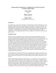
PLANNING AND DESIGN OF THE BAY TUNNEL<br />
R. John Caulfield<br />
<strong>Jacobs</strong> <strong>Associates</strong><br />
Victor S. Romero<br />
<strong>Jacobs</strong> <strong>Associates</strong><br />
Johanna I. Wong<br />
San Francisco Public Utilities Commission<br />
ABSTRACT<br />
The existing Hetch Hetchy water system, owned <strong>and</strong> operated by <strong>the</strong> San Francisco<br />
Public Utilities Commission (SFPUC), serves 2.4 million people within <strong>the</strong> San<br />
Francisco <strong>Bay</strong> Area. The system has existing 1920s-era pipelines crossing under <strong>the</strong><br />
<strong>Bay</strong> that are vulnerable to seismic damage from <strong>the</strong> nearby San Andreas <strong>and</strong> Hayward<br />
fault zones.<br />
The SFPUC plans to replace <strong>the</strong> pipelines with <strong>the</strong> first TBM-driven tunnel underneath<br />
<strong>the</strong> San Francisco <strong>Bay</strong>. The tunnel will be constructed using an Earth Pressure<br />
Balance machine. The new tunnel will pass under environmentally sensitive habitats<br />
<strong>and</strong> will be approximately eight kilometers (five miles) long with no intermediate shafts.<br />
The project challenges will include tunneling through a prominent buried bedrock ridge<br />
that transects <strong>the</strong> alignment <strong>and</strong> through s<strong>of</strong>t soils under <strong>the</strong> <strong>Bay</strong>. Seismic performance<br />
criteria include maintaining service flows after a large earthquake on one <strong>of</strong> <strong>the</strong><br />
active faults in close proximity to <strong>the</strong> project site.<br />
BACKGROUND<br />
The San Francisco Public Utilities Commission (SFPUC) manages a large water<br />
supply system <strong>of</strong> reservoirs, tunnels, pipelines, <strong>and</strong> treatment systems that stretches<br />
about 320 km (200 mi.) from <strong>the</strong> Hetch Hetchy Reservoir in Yosemite National Park to<br />
<strong>the</strong> City <strong>of</strong> San Francisco. The water comes from a protected watershed in <strong>the</strong> Sierra<br />
Nevada Mountains, <strong>and</strong> is some <strong>of</strong> <strong>the</strong> purest in <strong>the</strong> United States. The system is also<br />
economical, as it is almost entirely gravity-fed.<br />
The SFPUC is <strong>the</strong> third-largest municipal utility in <strong>the</strong> State <strong>of</strong> California <strong>and</strong> serves<br />
2.4 million residential, commercial, <strong>and</strong> industrial customers in <strong>the</strong> greater San Francisco<br />
<strong>Bay</strong> Area. Approximately one-third <strong>of</strong> <strong>the</strong> SFPUC’s delivered water goes to retail<br />
customers in <strong>the</strong> City <strong>of</strong> San Francisco, while wholesale deliveries to numerous o<strong>the</strong>r<br />
suburban agencies in Alameda, Santa Clara, <strong>and</strong> San Mateo counties comprise <strong>the</strong><br />
o<strong>the</strong>r two-thirds <strong>of</strong> deliveries. In November 2002, <strong>the</strong> SFPUC launched a $4.3 billion<br />
Water System Improvement Program (WSIP) to repair, replace, <strong>and</strong> seismically<br />
upgrade <strong>the</strong> system’s aging pipelines, tunnels, reservoirs, pump stations, storage tanks,<br />
<strong>and</strong> dams. The WSIP is funded by a bond measure approved by San Francisco voters.<br />
The program will achieve key service <strong>and</strong> operational goals related to seismic recovery,<br />
water quality, drought reliability, <strong>and</strong> sustainability. More than 75 projects in San Francisco<br />
<strong>and</strong> <strong>the</strong> surrounding region will be completed by <strong>the</strong> end <strong>of</strong> 2015.<br />
The SFPUC found two major pipeline arteries in <strong>the</strong> system to be particularly vulnerable<br />
in a seismic event. The replacement or upgrade <strong>of</strong> <strong>the</strong>se pipelines is a key<br />
685
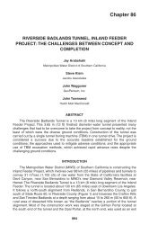
686 2007 RETC PROCEEDINGS<br />
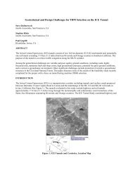
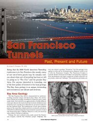
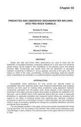
Figure 1.<br />
Schematic diagram <strong>of</strong> SFPUC’s water distribution system<br />
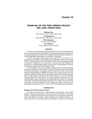
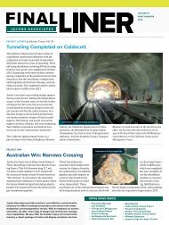
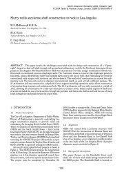
Figure 2.<br />
<strong>Bay</strong> Division Pipelines 1 <strong>and</strong> 2 at shoreline in East Palo Alto<br />
element <strong>of</strong> <strong>the</strong> WSIP. The two important pipelines are <strong>Bay</strong> Division Pipelines 1 <strong>and</strong> 2.<br />
These aging pipelines travel from <strong>the</strong> City <strong>of</strong> Newark, under <strong>the</strong> sou<strong>the</strong>rn portion <strong>of</strong><br />
<strong>the</strong> San Francisco <strong>Bay</strong>, up into <strong>the</strong> Western <strong>Bay</strong> mudflats, <strong>and</strong> <strong>the</strong>n across a pilesupported<br />
trestle into <strong>the</strong> City <strong>of</strong> East Palo Alto. (see Figure 2)<br />
The SFPUC commissioned initial engineering studies to evaluate various<br />
replacement <strong>and</strong> upgrade options. Options included upgrading <strong>the</strong> existing pipelines,<br />
replacing <strong>the</strong>m with cut <strong>and</strong> cover <strong>and</strong> submarine pipelines, <strong>and</strong> building a new tunnel.<br />
The studies showed that <strong>the</strong> preferred solution was to construct a new tunnel<br />
under <strong>the</strong> <strong>Bay</strong>.<br />
The tunnel will be constructed while <strong>the</strong> existing pipelines remain in service. The<br />
existing pipelines, <strong>and</strong> a new pipeline to be constructed, will be tied in to <strong>the</strong> tunnel at<br />
ei<strong>the</strong>r end during short outage windows. The shorter windows will limit system disruption<br />
<strong>and</strong> avoid customer supply issues.
PLANNING AND DESIGN OF THE BAY TUNNEL 687<br />
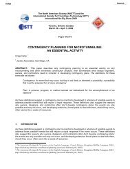
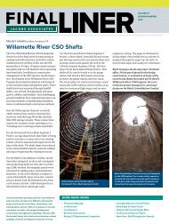
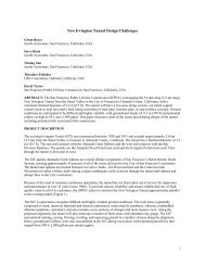
Figure 3.<br />
Proposed <strong>Bay</strong> <strong>Tunnel</strong> horizontal alignment<br />
FACILITY LAYOUT<br />
The <strong>Bay</strong> <strong>Tunnel</strong> will be located between two shafts. The presence <strong>of</strong> environmentally-sensitive<br />
habitats on <strong>the</strong> <strong>Bay</strong> margins resulted in <strong>the</strong> need for an 8 km (5 mi)-long<br />
tunnel with only launching <strong>and</strong> receiving shafts <strong>and</strong> no intermediate construction<br />
shafts. These two shafts will be located on properties owned by SFPUC in <strong>the</strong> City <strong>of</strong><br />
Newark (Newark shaft) <strong>and</strong> <strong>the</strong> City <strong>of</strong> East Palo Alto (Ravenswood shaft), as shown<br />
on Figure 3. The shafts are expected to be constructed using diaphragm slurry wall<br />
construction methods with tremied structural concrete slabs tied into <strong>the</strong> shaft bottoms.<br />
The TBM launching <strong>and</strong> construction shaft located at <strong>the</strong> Ravenswood site will be<br />
approximately 17.7m (58 ft) in diameter <strong>and</strong> 33.5m (110 ft) deep. The receiving shaft<br />
located at <strong>the</strong> Newark site will be approximately 8.5m (28 ft) in diameter <strong>and</strong> 22.5m<br />
(74 ft) deep.<br />
The preferred horizontal alignment was chosen to meet identified design <strong>and</strong> constructability<br />
criteria. Criteria included providing straight departures from <strong>the</strong> shaft sites<br />
<strong>and</strong> maintaining minimum 305m (1,000-ft) radius curves. Pile supported structures<br />
planned along <strong>the</strong> shoreline <strong>of</strong> <strong>the</strong> adjacent rail corridor made it desirable to cross this<br />
corridor onshore <strong>and</strong> at some distance from <strong>the</strong> shoreline on <strong>the</strong> Ravenswood side <strong>of</strong><br />
<strong>the</strong> <strong>Bay</strong>. In <strong>the</strong> Newark area, a horizontal curve was placed in <strong>the</strong> alignment to avoid<br />
schedule delays that might be caused by passing under a parcel owned by a private<br />
party that was unwilling to grant an underground easement. The total length <strong>of</strong> <strong>the</strong> preferred<br />
alignment is 7,994m (26,226 ft).<br />
The preferred vertical alignment was based upon a number <strong>of</strong> different design <strong>and</strong><br />
constructability criteria, including maintaining minimum clearances under <strong>the</strong> bottom <strong>of</strong><br />
<strong>the</strong> San Francisco <strong>Bay</strong> <strong>and</strong> keeping <strong>the</strong> tunnel as shallow as possible to reduce construction<br />
costs. It was also necessary to keep <strong>the</strong> tunnel alignment under <strong>the</strong> Young<br />
<strong>Bay</strong> Mud deposits to avoid negative impacts to seismic performance.
688 2007 RETC PROCEEDINGS<br />
Table 1.<br />
Description <strong>of</strong> anticipated geologic units<br />
Formation<br />
Young <strong>Bay</strong> Mud<br />
San Antonio Formation (also described as <strong>the</strong><br />
Merritt-Posey-San Antonio Formation)<br />
Old <strong>Bay</strong> Clay<br />
Franciscan Complex<br />
Description<br />
S<strong>of</strong>t to medium silty clay<br />
Interlayered medium stiff to hard silt <strong>and</strong> clay,<br />
with loose to dense s<strong>and</strong> lenses<br />
Stiff to hard silty clay with dense s<strong>and</strong> lenses<br />
Sedimentary <strong>and</strong> low-grade metamorphic rock,<br />
highly wea<strong>the</strong>red<br />
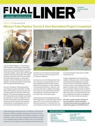
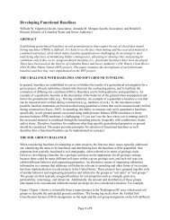
Figure 4.<br />
Geologic pr<strong>of</strong>ile along <strong>the</strong> proposed <strong>Bay</strong> <strong>Tunnel</strong> alignment<br />
GEOLOGIC CONDITIONS<br />
Site Geology<br />
The initial phase <strong>of</strong> <strong>the</strong> field geotechnical investigation was completed in 2006.<br />
The field investigations included a series <strong>of</strong> marine-based borings across <strong>the</strong> San<br />
Francisco <strong>Bay</strong>, <strong>and</strong> l<strong>and</strong>-based borings <strong>and</strong> cone penetrometers on <strong>the</strong> Newark <strong>and</strong><br />
Ravenswood site locations. In addition to <strong>the</strong> conventional exploration, an extensive<br />
marine- <strong>and</strong> l<strong>and</strong>-based geophysics program was performed along <strong>the</strong> majority <strong>of</strong> <strong>the</strong><br />
proposed alignment corridor to help <strong>the</strong> design team make interpretations between<br />
boreholes. Suspension logging was also performed in selected boreholes at <strong>the</strong><br />
Ravenswood <strong>and</strong> Newark sites. As a result <strong>of</strong> <strong>the</strong> field investigation program, four primary<br />
geologic units were identified as underlying <strong>the</strong> proposed tunnel alignment corridor.<br />
These geologic units are summarized in Table 1.<br />
After <strong>the</strong> initial geotechnical investigation <strong>and</strong> associated laboratory testing were<br />
complete, a long section plot was generated showing <strong>the</strong> stratigraphy <strong>of</strong> <strong>the</strong> proposed<br />
alignment. The anticipated geology based on <strong>the</strong> results <strong>of</strong> this stratigraphy plot is<br />
summarized on Figure 4.<br />
Groundwater<br />
The geotechnical l<strong>and</strong>-based investigation included <strong>the</strong> installation <strong>of</strong> multilevel,<br />
vibrating-wire piezometers to monitor groundwater pressures near <strong>the</strong> two shaft sites.<br />
Piezometer readings indicate that <strong>the</strong> groundwater pressures are generally consistent<br />
at 1 to 3.4m (3 to 11 ft) below <strong>the</strong> ground surface <strong>and</strong> are influenced by tidal variations.
PLANNING AND DESIGN OF THE BAY TUNNEL 689<br />
Figure 5.<br />
Distribution <strong>of</strong> USCS soil types along <strong>the</strong> proposed tunnel alignment<br />
Readings between piezometer levels indicate that <strong>the</strong>re is some hydraulic conductivity<br />
between <strong>the</strong> individual geologic units.<br />
Anticipated <strong>Tunnel</strong>ing Conditions<br />
Geotechnical evaluations resulted in <strong>the</strong> tunnel being situated in <strong>the</strong> San Antonio<br />
Formation to optimize tunneling conditions, depth, <strong>and</strong> seismic performance. The tunnel<br />
section was superimposed on <strong>the</strong> geologic pr<strong>of</strong>ile such that it was possible to<br />
locate localized intersections <strong>of</strong> <strong>the</strong> stratigraphy within <strong>the</strong> tunnel envelope. Using <strong>the</strong><br />
tunnel envelope stratigraphy, including one tunnel diameter above <strong>and</strong> below, it was<br />
possible to develop a preliminary assessment <strong>of</strong> <strong>the</strong> distribution <strong>of</strong> soil types anticipated<br />
to be encountered along <strong>the</strong> alignment. This allowed <strong>the</strong> design team to make a<br />
recommendation about what tunneling methods would be most appropriate.<br />
Laboratory testing, including sieve analyses <strong>and</strong> hydrometer testing, was done on<br />
selected soil samples to determine <strong>the</strong> gradation curves for <strong>the</strong> various soil types sampled<br />
in <strong>the</strong> borings. This data, along with Atterberg Limits testing <strong>and</strong> visual/manual<br />
soil classification were used to classify soil with <strong>the</strong> Unified Soil Classification System<br />
(USCS).<br />
The San Antonio Formation consists <strong>of</strong> interbedded clays, silts <strong>and</strong> s<strong>and</strong>s. The<br />
entire tunnel alignment is under <strong>the</strong> water table, subject to approximately 3.2 bars<br />
(48 psi) <strong>of</strong> hydrostatic pressure. To select <strong>and</strong> specify a TBM, it was important to quantify<br />
<strong>the</strong> amount <strong>of</strong> soil with a high fines content (clays <strong>and</strong> silts) <strong>and</strong> <strong>the</strong> amount <strong>of</strong> soil<br />
comprised <strong>of</strong> coarse materials (s<strong>and</strong>s <strong>and</strong> gravels). It was also important to characterize<br />
<strong>the</strong> stratigraphic distribution <strong>of</strong> <strong>the</strong> soil types, particularly for poorly-graded s<strong>and</strong>s<br />
<strong>and</strong> gravels, which can create problems for some TBMs if <strong>the</strong>y are encountered in<br />
excessively thick or laterally continuous layers ra<strong>the</strong>r than isolated lenses.<br />
Some basic statistical analysis was performed to syn<strong>the</strong>size <strong>the</strong> data <strong>and</strong> draw<br />
some preliminary conclusions regarding soil type distributions. Figure 5 summarizes<br />
<strong>the</strong> results <strong>of</strong> <strong>the</strong> statistical analysis. This table includes data from one tunnel diameter<br />
above <strong>and</strong> one diameter below <strong>the</strong> proposed tunnel alignment in order to provide a
690 2007 RETC PROCEEDINGS<br />
Table 2. Review <strong>of</strong> squeezing conditions in clay <strong>and</strong> silt deposits along <strong>the</strong> proposed tunnel<br />
alignment<br />
Degree <strong>of</strong> Squeezing<br />
Probability <strong>of</strong> Occurrence Based on<br />
Number <strong>of</strong> Test Samples<br />
Minor 29%<br />
Moderate 52%<br />
Severe 13%<br />
Extreme 6%<br />
more complete picture <strong>of</strong> <strong>the</strong> kinds <strong>of</strong> soils expected <strong>and</strong> <strong>the</strong> variability which may exist<br />
within <strong>the</strong> tunnel horizon.<br />
Within <strong>and</strong> near <strong>the</strong> tunnel envelope, <strong>the</strong> majority <strong>of</strong> materials are low to high plasticity<br />
clays. Smaller amounts <strong>of</strong> silty <strong>and</strong> s<strong>and</strong>y materials are present. The percentage<br />
<strong>of</strong> fine grained material (relative to coarse grained material) tends to increase with tunnel<br />
depth. However, within <strong>the</strong> tunnel envelope a significant amount <strong>of</strong> coarser s<strong>and</strong>s<br />
are also present. Stratigraphic thicknesses were also analyzed <strong>and</strong> it was concluded<br />
that when <strong>the</strong> excavation does encounter <strong>the</strong> coarser grained materials, much <strong>of</strong> <strong>the</strong><br />
time it will encounter a full-face <strong>of</strong> coarse materials, as opposed to a mixed-face <strong>of</strong><br />
coarse <strong>and</strong> fine materials.<br />
The stability behavior <strong>of</strong> clay <strong>and</strong> silt deposits was reviewed by computing <strong>the</strong><br />
overload factor (also known as <strong>the</strong> stability factor) along <strong>the</strong> proposed alignment<br />
depth. The overload factor (OF) was calculated using <strong>the</strong> following equation:<br />
P<br />
OF z – P<br />
= ------------------- a<br />
S u<br />
Where<br />
P z = <strong>the</strong> total vertical pressure at tunnel depth<br />
P a = assumed to be atmospheric pressure (for an unsupported face)<br />
S u = <strong>the</strong> undrained strength from unconsolidated-undrained triaxial tests<br />
A breakdown <strong>of</strong> <strong>the</strong> degree <strong>of</strong> squeezing behavior within <strong>the</strong> clay <strong>and</strong> silt deposits<br />
is summarized in Table 2.<br />
It should be noted that <strong>the</strong> above analysis assumed an unsupported face, which<br />
will not be <strong>the</strong> case with <strong>the</strong> <strong>Bay</strong> <strong>Tunnel</strong>, since pressure-face methods will be specified.<br />
However, this analysis illustrates why pressure-face methods are required for most <strong>of</strong><br />
<strong>the</strong> excavation. Because approximately 70% <strong>of</strong> <strong>the</strong> tunnel could experience moderate<br />
to extreme squeezing conditions, it was recommended that control <strong>and</strong> regulation <strong>of</strong><br />
face pressure be maintained through pressurized mode excavation. The majority <strong>of</strong><br />
extreme squeezing <strong>and</strong> severe squeezing behavior occurs at shallower depths <strong>and</strong> <strong>the</strong><br />
degree <strong>of</strong> squeezing tends to decrease with depth. This is because <strong>the</strong> shear strength<br />
<strong>of</strong> <strong>the</strong> material increases significantly with depth, <strong>and</strong> governs <strong>the</strong> degree <strong>of</strong> squeezing.<br />
The pressurized-face TBM h<strong>and</strong>les squeezing ground conditions better than o<strong>the</strong>r<br />
methods since face pressures are balanced, preventing <strong>the</strong> soil at <strong>the</strong> face from<br />
squeezing. However, <strong>the</strong> main area <strong>of</strong> concern in <strong>the</strong> <strong>Bay</strong> <strong>Tunnel</strong> is along <strong>the</strong> body <strong>of</strong><br />
<strong>the</strong> TBM, where high friction forces may occur due to <strong>the</strong> relaxation <strong>of</strong> <strong>the</strong> material into<br />
<strong>the</strong> steering gap created by <strong>the</strong> cutterhead overcut. Solutions for <strong>the</strong>se conditions<br />
include using shield lubrication with bentonite, limiting work stops in high risk areas,<br />
making provisions for sufficient overcut on <strong>the</strong> cutterhead <strong>and</strong> providing additional<br />
thrust capacity.
PLANNING AND DESIGN OF THE BAY TUNNEL 691<br />
In addition to <strong>the</strong> potential squeezing behavior <strong>of</strong> <strong>the</strong> cohesive fine grained materials,<br />
<strong>the</strong> silts <strong>and</strong> s<strong>and</strong>s present along <strong>the</strong> alignment could present running or flowing<br />
ground conditions if <strong>the</strong> face is not pressurized during excavation.<br />
In addition to <strong>the</strong> San Antonio Formation, <strong>the</strong> tunnel excavation is expected to<br />
encounter a short section <strong>of</strong> highly wea<strong>the</strong>red Franciscan Formation bedrock. The<br />
bedrock is expected to consist <strong>of</strong> highly wea<strong>the</strong>red s<strong>and</strong>stone, shale, serpentinite, <strong>and</strong><br />
o<strong>the</strong>r rock types typically associated with <strong>the</strong> Franciscan Formation.<br />
SEISMIC CHARACTERIZATION<br />
Characterizing <strong>the</strong> potential seismic impacts on <strong>the</strong> facility <strong>and</strong> developing seismic<br />
design parameters were critical activities in <strong>the</strong> design process. The SFPUC expects<br />
<strong>the</strong> water system to be fully operational following a major seismic event.<br />
The proposed <strong>Bay</strong> <strong>Tunnel</strong> is located in a seismically active area—central coastal<br />
California. Although <strong>the</strong> proposed alignment does not cross any identified active faults,<br />
it is situated between <strong>the</strong> San Andreas <strong>and</strong> Hayward faults, which are capable <strong>of</strong> generating<br />
large (M [moment magnitude] ≥7) earthquakes. There are also numerous<br />
smaller active faults within 50 km (30 mi) <strong>of</strong> <strong>the</strong> proposed alignment. A total <strong>of</strong> 15<br />
earthquakes <strong>of</strong> M ≥ 6.0 have occurred in <strong>the</strong> San Francisco <strong>Bay</strong> region between 1850<br />
<strong>and</strong> <strong>the</strong> present. These include <strong>the</strong> 1906 M7.9 San Francisco earthquake <strong>and</strong> <strong>the</strong><br />
1989 M6.9 Loma Prieta earthquake. The <strong>Bay</strong> <strong>Tunnel</strong> project is expected to experience<br />
significant ground shaking during its design life <strong>of</strong> 100 years.<br />
As required by <strong>the</strong> SFPUC’s general seismic design requirements, <strong>the</strong> <strong>Bay</strong> <strong>Tunnel</strong><br />
will be designed for ground motions that will have a 5% probability <strong>of</strong> exceedance in<br />
50 years (975-year approximate return period).<br />
As part <strong>of</strong> preliminary design studies, a probabilistic seismic hazard analysis<br />
(PSHA) for ground shaking along <strong>the</strong> alignment was performed. The purpose <strong>of</strong> this<br />
evaluation was to estimate <strong>the</strong> levels <strong>of</strong> ground motions at a specified exceedance<br />
probability. Deterministic scenario ground motions were also calculated <strong>and</strong> compared<br />
to <strong>the</strong> probabilistic ground motions. An evaluation <strong>of</strong> liquefaction was also performed.<br />
ENVIRONMENTAL CONSTRAINTS<br />
The San Francisco <strong>Bay</strong> margins consist <strong>of</strong> environmentally sensitive mudflats, salt<br />
marshl<strong>and</strong>, <strong>and</strong> vernal pool habitat. The Don Edwards Wildlife Refuge, <strong>the</strong> first urban<br />
National Wildlife Refuge established in <strong>the</strong> United States, is located along <strong>the</strong> eastern<br />
portion <strong>of</strong> <strong>the</strong> project site. Many endangered species, like <strong>the</strong> California clapper rail<br />
<strong>and</strong> salt marsh harvest mouse, live in <strong>the</strong> wildlife refuge. One <strong>of</strong> <strong>the</strong> key motivations for<br />
<strong>the</strong> proposed tunnel system was <strong>the</strong> benefit <strong>of</strong> putting <strong>the</strong> system underground so that<br />
environmentally-sensitive areas would not be disrupted. In fact, <strong>the</strong> geologic investigations<br />
for <strong>the</strong> project were very difficult to permit <strong>and</strong> to obtain access for field work.<br />
Only specific windows <strong>of</strong> opportunity were available for <strong>the</strong> investigations <strong>and</strong> many<br />
constraints were placed upon <strong>the</strong> work operations.<br />
Ano<strong>the</strong>r environmental issue at <strong>the</strong> project site is hazardous waste contamination.<br />
Within <strong>the</strong> area surrounding <strong>the</strong> Newark receiving shaft, elevated levels <strong>of</strong> chlorinated<br />
volatile organic compounds in <strong>the</strong> groundwater have been identified. The groundwater<br />
in this area will require pretreatment <strong>and</strong> special h<strong>and</strong>ling prior to discharge. The soil<br />
will require special h<strong>and</strong>ling <strong>and</strong> disposal.<br />
Elevated levels <strong>of</strong> chrysotile asbestos were also found in some <strong>of</strong> <strong>the</strong> samples<br />
from <strong>the</strong> Franciscan Complex bedrock materials that were encountered. Portions <strong>of</strong><br />
<strong>the</strong> materials excavated from this area will require disposal as hazardous waste.
692 2007 RETC PROCEEDINGS<br />
SHAFT AND TUNNEL CONSTRUCTION METHODOLOGY<br />
The <strong>Bay</strong> <strong>Tunnel</strong> will be constructed as a two-pass system. The first pass will<br />
involve a TBM-excavated tunnel, with initial ground support consisting <strong>of</strong> a bolted <strong>and</strong><br />
gasketed, precast concrete segmental lining erected immediately behind <strong>the</strong> TBM. The<br />
final lining will consist <strong>of</strong> ei<strong>the</strong>r a welded steel pipe or reinforced concrete cylinder pipe,<br />
ei<strong>the</strong>r 2.74 or 3.05m (108 or 120 in) in finished diameter. Once <strong>the</strong> final lining is<br />
installed inside <strong>the</strong> tunnel, <strong>the</strong> annular space between <strong>the</strong> outside <strong>of</strong> <strong>the</strong> pipe <strong>and</strong> <strong>the</strong><br />
initial support will be backfilled with cellular concrete.<br />
The shafts on this project are required to be watertight to reduce <strong>the</strong> risk, particularly<br />
at <strong>the</strong> Newark site, <strong>of</strong> disturbing contaminated groundwater plumes. Excavation<br />
support systems that were identified as potential alternatives included secant piles,<br />
slurry walls, <strong>and</strong> ground freezing. Each alternative was evaluated for construction cost<br />
<strong>and</strong> schedule, constructability <strong>of</strong> <strong>the</strong> wall to <strong>the</strong> required depth, water-tightness, <strong>and</strong><br />
continuity <strong>of</strong> <strong>the</strong> wall. The diaphragm slurry wall option is best suited for construction <strong>of</strong><br />
<strong>the</strong> Ravenswood <strong>and</strong> Newark Shafts. Diaphragm slurry walls provide maximum safety<br />
against leakage through <strong>the</strong> wall <strong>and</strong> can be constructed without any “windows.” The<br />
stiffness <strong>of</strong> <strong>the</strong> wall also helps to reduce adjacent ground settlements resulting from<br />
wall deflection. Once tunnel excavation <strong>and</strong> final lining installation are complete, a<br />
steel riser pipe will be installed in <strong>the</strong> shafts <strong>and</strong> <strong>the</strong> annular space backfilled with a<br />
combination <strong>of</strong> concrete <strong>and</strong> controlled low strength material.<br />
Due to <strong>the</strong> large percentage <strong>of</strong> silts <strong>and</strong> clays <strong>and</strong> <strong>the</strong> cohesive nature <strong>of</strong> <strong>the</strong> soils,<br />
an EPB TBM is <strong>the</strong> most appropriate mechanical excavation method for <strong>the</strong> tunnel. As<br />
can be noted in Table 2, <strong>the</strong> majority <strong>of</strong> materials encountered within <strong>the</strong> borings at<br />
tunnel level are fine grained <strong>and</strong> cohesive material. The remainder will represent ei<strong>the</strong>r<br />
a full-face or mixed face <strong>of</strong> s<strong>and</strong>y soil. In conditions where s<strong>and</strong> <strong>and</strong> clay are present in<br />
<strong>the</strong> face, <strong>the</strong> cutterhead will tend to mix <strong>the</strong> soils <strong>and</strong> prevent s<strong>and</strong> under groundwater<br />
pressure from becoming uncontrollable. The coarser grained s<strong>and</strong>y materials are<br />
expected to require ground conditioners in some combination <strong>of</strong> foam, polymers <strong>and</strong><br />
bentonite. In most cases it is expected that ground conditioning injected from <strong>the</strong> TBM<br />
cutterhead will cope with most, if not all, <strong>of</strong> <strong>the</strong> materials expected. The highly wea<strong>the</strong>red<br />
bedrock materials are also expected along a short section <strong>of</strong> <strong>the</strong> alignment. The<br />
TBM cutterhead will be outfitted with appropriate excavation tools to h<strong>and</strong>le <strong>the</strong>se<br />
materials when <strong>the</strong>y are encountered.<br />
PROJECT SCHEDULE<br />
The final design for <strong>the</strong> <strong>Bay</strong> <strong>Tunnel</strong> is currently underway <strong>and</strong> is expected to be<br />
complete in November 2007. The project environmental documentation is being performed<br />
in parallel with <strong>the</strong> design <strong>and</strong> is expected to be completed in 2008. The project<br />
is expected to go to construction in July 2009, with an anticipated completion date <strong>of</strong><br />
August 2013.<br />
SUMMARY AND CONCLUSIONS<br />
The proposed 8 kilometer (5 mile) long <strong>Bay</strong> <strong>Tunnel</strong> is a critical lifeline water supply<br />
facility for <strong>the</strong> City <strong>of</strong> San Francisco <strong>and</strong> <strong>the</strong> San Francisco peninsula communities. It<br />
will be <strong>the</strong> first tunnel excavated by a TBM under <strong>the</strong> San Francisco <strong>Bay</strong>. The proposed<br />
tunnel is located in an area <strong>of</strong> high seismicity <strong>and</strong> will need to remain serviceable after<br />
a large earthquake on nearby active faults. It is expected to encounter s<strong>of</strong>t sediments,<br />
primarily s<strong>and</strong>y <strong>and</strong> silty clays, that will be well suited to <strong>the</strong> Earth Pressure Balance<br />
excavation methodology.
PLANNING AND DESIGN OF THE BAY TUNNEL 693<br />
ACKNOWLEDGMENTS<br />
The authors wish to acknowledge <strong>the</strong> support provided by <strong>the</strong> San Francisco Public<br />
Utilities Commission <strong>and</strong> <strong>Jacobs</strong> <strong>Associates</strong> for <strong>the</strong> preparation <strong>of</strong> this publication.<br />
REFERENCES<br />
<strong>Jacobs</strong> <strong>Associates</strong> <strong>and</strong> Fugro West, December, 2006. <strong>Bay</strong> Division Pipeline Reliability<br />
Upgrade (CUW36801), <strong>Bay</strong> <strong>Tunnel</strong> Project, Draft Geotechnical Interpretive<br />
Technical Memor<strong>and</strong>um.<br />
<strong>Jacobs</strong> <strong>Associates</strong> <strong>and</strong> URS Corporation, November, 2006. <strong>Bay</strong> Division Pipeline<br />
Reliability Upgrade (CUW36801), <strong>Bay</strong> <strong>Tunnel</strong> Project, Draft Geotechnical Data<br />
Report.<br />
San Francisco Public Utilities Commission. May, 2006. <strong>Bay</strong> Division Pipeline Reliability<br />
Upgrade, Phase 3, Conceptual Engineering Report. Prepared by Engineering<br />
Management Bureau <strong>and</strong> Project Management Bureau <strong>and</strong> Parsons, Project<br />
CUW36801, Control No. 201441.