Premier Electric Projection Screen by Draper - AVsuperstore.com
Premier Electric Projection Screen by Draper - AVsuperstore.com
Premier Electric Projection Screen by Draper - AVsuperstore.com

Create successful ePaper yourself
Turn your PDF publications into a flip-book with our unique Google optimized e-Paper software.
Installation Instructions<br />
<strong>Premier</strong> <strong>Electric</strong> <strong>Projection</strong> <strong>Screen</strong> <strong>by</strong> <strong>Draper</strong><br />
Caution<br />
➀ Read instructions through <strong>com</strong>pletely before proceeding.<br />
➁ Follow instructions carefully. Installation con trary to instructions in val i-<br />
dates warranty.<br />
➂ <strong>Screen</strong> should be accessible for <strong>com</strong>plete removal should fabric<br />
be<strong>com</strong>e damaged or should other ser vice be required.<br />
➃ <strong>Screen</strong> should be installed level (using a carpenter’s level).<br />
➄ Nothing should be fastened to screen dowel or viewing surface.<br />
➅ Operating switch(es) packed separately in screen carton. Do not<br />
discard with packing material.<br />
➆ <strong>Screen</strong> operates on 110-120V, 60 Hz. current.<br />
NOTE: <strong>Screen</strong> has been thoroughly inspected and tested at factory and<br />
found to be operating properly prior to shipment.<br />
Hanging <strong>Screen</strong><br />
General:<br />
When locating viewing surface and checking clear ance for screen’s op er a tion,<br />
remember surface is centered in case. Handle case care ful ly to protect fi nish.<br />
Regardless of mounting method, screen should be positively and securely<br />
supported so that vibration or even abusive pulling on the viewing surface will<br />
not cause case to work loose or fall. Installer must insure that fas ten ers used<br />
are of adequate strength and suitable for the mounting sur face chosen.<br />
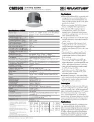
Suspended Installation:<br />
Suspend screens from holes in endcaps as shown. “S” hooks are included,<br />
but chains (or cable) and turn buck les should be provided <strong>by</strong> installer. Chains<br />
should be attached to beams or other struc tur al mem bers. Turn buck les should<br />
be adjusted so screen hangs level.<br />
Wall Installation:<br />
Mount screen through holes in back of endcaps as shown. Installer should<br />
furnish screws, toggle bolts, molly bolts, nylon or lead anchors as required.<br />
Recessed Installation:<br />
Recess should permit access for removal of screen if necessary. <strong>Screen</strong> may<br />
be mounted as in suspended or wall installation. Optional Ceiling Opening<br />
Trim Kit also available; see diagram on page 2 and separate instruction sheet<br />
(included with Ceiling Opening Trim Kit).<br />
Elec tri cal Con nec tions<br />
<strong>Screen</strong> operates on 110-120V, 60 Hz. current. Junction box is located inside<br />
left endcap and cover plate is secured to endcap with two screws. Junc tion<br />
box contains terminal strip, per wiring diagram on reverse.<br />
<strong>Screen</strong> Case<br />
Back<br />
Ceiling Tile<br />
(By others)<br />
Copyright © 2005 <strong>Draper</strong> Inc. Form <strong>Premier</strong>_Inst05-R Printed in U.S.A.<br />
<strong>Screen</strong> is shipped with internal wiring <strong>com</strong>plete and control switch(es) fully<br />
boxed. Wire connecting screen to switch(es) and switch(es) to power supply<br />
should be furnished <strong>by</strong> installer. Connections should be made in ac cor dance<br />
with wiring diagram sup plied, and wiring should <strong>com</strong>ply with na tion al and local<br />
elec tri cal codes.<br />
All operating switches should be “Off” before power is connected.<br />
Operation<br />
CAUTION—Important Instructions: Shipping support brackets must be<br />
removed from each end of dowel during initial operation, before screen is<br />
operated in UP direction. After screen is installed, lower viewing surface to<br />
access screws holding brackets to dowel. Loosen hex head screw, remove<br />
bracket and retighten screw at each end of dowel. Raise and lower viewing<br />
Dowel<br />
Shipping<br />
Bracket<br />
surface several times to confirm satisfactory op er a tion. If viewing surface does<br />
not operate properly, turn power off and check electrical con nec tions.<br />
110-120V Single Station Control—3-position up-off-down switch per mits<br />
operation to be stopped at any point. Factory adjusted limit switches<br />
automatically stop screen when fully down or fully up.<br />
110-120V Multiple Station Control—Switches are similar in ap pear ance<br />
to 110-120V Single Station Control. <strong>Screen</strong> stops when switch is re leased<br />
and may be re start ed in either direction. Factory adjusted limit switch es stop<br />
screen au to mat i cal ly when fully up or fully down.<br />
24V Control—Three-button up-stop-down switch(es) stop at any point<br />
desired, operate in any sequence. Factory adjusted limit switches<br />
au to mat i cal ly stop screen when fully up or fully down.<br />
Key Operated Switching—Two kinds of key-operated switches are op tion al ly<br />
available with this unit. ➀ The key-operated power sup ply switch controls<br />
power to the screen and switches. When it is “off”, the switches will not<br />
operate screen. Key may be removed from the switch in either “on” or “off”<br />
position. ➁ A three-po si tion key switch per mits the screen to be operated<br />
directly <strong>by</strong> key. In this case, the screen’s operator must always have a key.<br />
RS232/Ethernet—Serial <strong>com</strong>munication and network <strong>com</strong>munication<br />
optionally available with wall switches, RF or IR remote.<br />
Adjustments<br />
<strong>Screen</strong> has been factory set and should not nor mal ly require further<br />
ad just ment. However, if you desire to change the “up” and “down” stop ping<br />
positions, proceed as follows:<br />
CAUTION: Be sure all switches are in “off” position before ad just ing limit<br />
switches. Always be pre pared to shut screen off man u al ly when new<br />
ad just ment is being tested. <strong>Screen</strong> may be se vere ly dam aged if viewing<br />
surface is al lowed to run too far up or too far down.<br />
Adjusting “fully up” position — “Up” stopping position may be ad just ed <strong>by</strong><br />
turning the yellow limit switch adjustment socket. The yellow socket is located<br />
on left end of screen roller and is ac ces si ble to a screw driv er/Allen wrench<br />
(4mm or 5 /32"). Turn ing the socket coun ter clock wise will allow the view ing<br />
surface to retract farther into the case. Turn ing it clockwise will cause the<br />
sur face to stop farther out of the case. One full revolution of the socket will<br />
alter the stopping position of the view ing surface <strong>by</strong> ap prox i mate ly 1 1 /2".<br />
Adjusting “fully down” position — “Down” stopping position may be<br />
adjusted <strong>by</strong> turning the white limit switch adjustment socket. The white socket<br />
is located on the left end of screen roller and is ac ces si ble to a screw driv er/<br />
Allen wrench (4mm or 5 /32"). Turning the socket coun ter clock wise will allow the<br />
viewing surface to run farther down. Turning it clockwise will shorten viewing<br />
surface, causing it to stop in a less extended position. At no time should<br />
viewing surface be unrolled enough to expose any part of screen roller.<br />
Please Note: Instructions for adjusting <strong>Draper</strong>’s Tab-Tension<br />
System are on page 2.<br />
If you encounter any difficulties installing or ser vic ing<br />
your <strong>Premier</strong> screen, call your dealer or <strong>Draper</strong>, Inc.<br />
Spiceland, In di ana, U.S.A., (765) 987-7999; fax (765)<br />
987-7142; or e-mail draper@draperinc.<strong>com</strong>.
<strong>Premier</strong> <strong>by</strong> <strong>Draper</strong><br />
Types of Installation<br />
Suspended<br />
1 13 /16"<br />
5 1 /4"<br />
Case Dimensions<br />
Mounting<br />
hole<br />
Page 2 of 2<br />
Appropriate hardware<br />
provided <strong>by</strong> installer.<br />
5 7 /8"<br />
Wall<br />
Appropriate hardware<br />
provided <strong>by</strong> installer.<br />
1"<br />
15/16"<br />
Single Station Control<br />
7 /8" dia.<br />
electrical<br />
connection<br />
hole<br />
21/8"<br />
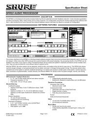
Wiring Diagrams<br />
Multiple Station Control<br />
Optional Ceiling Opening Trim Kit<br />
(Dims-Side View)<br />
Dashed wiring<br />
<strong>by</strong> electrician<br />
Internal <strong>Screen</strong> Wiring<br />
White (Common)<br />
Black (Down)<br />
Red (Up)<br />
Green (Ground)<br />
Internal <strong>Screen</strong> Wiring<br />
White (Common)<br />
Black (Down)<br />
Red (Up)<br />
Green (Ground)<br />
Cap off with wire<br />
nut and tape<br />
Blue<br />
Control<br />
switch<br />
Single gang box <strong>by</strong> others<br />
Min. 4" x 2 1 /8" x 1 7 /8" deep<br />
Red<br />
Blue<br />
Red<br />
Black<br />
Black<br />
Dashed wiring<br />
<strong>by</strong> electrician<br />
Tab-Tension Adjustment<br />
Procedure for <strong>Premier</strong><br />
➀ Determine which side requires adjustment.<br />
➁ Secure dowel with one hand.<br />
Caution: Do not touch or bend surface.<br />
➂ Using Philips-head screwdriver, depress springloaded<br />
adjustment screw (see drawing below) and<br />
slowly turn clockwise to tighten tension, or<br />
counterclockwise to loosen tension. The screw<br />
adjusts in ¼ turn increments. Adjust only one<br />
increment (¼ turn).<br />
➃ If problem is not corrected, leave screen in position<br />
for 24 hours to allow surface material to stretch into<br />
position.<br />
➄ If problem still is not corrected, repeat steps 2 and 3.<br />
Dowel<br />
8"<br />
2 1 /8"<br />
4"<br />
Tensioning<br />
Cable<br />
6 3 /4"<br />
Adjustment<br />
Screw<br />
1 1 /16"<br />
2 1 /16"<br />
See separate Serial Communication-RS232<br />
Instruction<br />
sheet for enabling<br />
RS232 with the MC1.<br />
To 110-120V Line<br />
Location of key<br />
operated on-off<br />
switch if furnished<br />
Red<br />
Red<br />
To 110-120V Line<br />
Black<br />
Black<br />
Location of key<br />
operated on-off<br />
switch if furnished<br />
Blue<br />
Blue<br />
White-Common to screen & 110-120V AC Neutral<br />
Red-to screen (directional)<br />
Brown-to screen (directional)<br />
Yellow-to 110-120V AC-Hot<br />
Black-to 110-120V AC-Hot<br />
Green-Ground<br />
Dashed wiring <strong>by</strong> electrician<br />
Low voltage wiring <strong>by</strong> others<br />
Eye Port for IR Eye, RF Receiver or LED<br />
Wall Switch. For more than one of<br />
these, a splitter is required.<br />
3 Button Wall Switch<br />
DOWN - Black<br />
COM - White<br />
UP - Red<br />
Aux Port for connecting additional LVC-III<br />
modules (up to six total can be linkedconnect<br />
from Aux to Eye).<br />
Single gang box <strong>by</strong> others<br />
Min. 4" x 2 1 /8" x 1 7 /8" deep.<br />
3 shown. More or less equally<br />
feasible.<br />
Two-Way Serial Communication (RS232) with MC1<br />
Fuse<br />
Low Voltage & Wireless Control<br />
Program LED<br />
MC1<br />
White-Common to screen & 110-120V AC Neutral<br />
Red-to <strong>Screen</strong> (directional)<br />
Brown-to <strong>Screen</strong> (directional)<br />
Black-Hot to 110-120V AC<br />
Green/Yellow-Ground<br />
Low Voltage Wiring <strong>by</strong> others<br />
AC Wiring <strong>by</strong> electrician<br />
RS232 Data FROM Control System<br />
RS232 Data TO Control System<br />
Signal Ground & Manual Switch Common<br />
Manual Switch Down<br />
Manual Switch Up<br />
Eye Port for IR Eye. For RF Receiver or LED<br />
Wall Switch, a Splitter and a Power Supply<br />
is required. Plug RF Receiver or LED Wall<br />
Switch and Power Supply into splitter, then<br />
run cable from Splitter to MC1 Eye Port.<br />
To 110-120V Line<br />
To 110-120V Line<br />
Internal <strong>Screen</strong> Wiring<br />
Location of key<br />
operated on-off<br />
switch if furnished<br />
Location of key<br />
operated on-off<br />
switch if furnished<br />
White (Common)<br />
Red (Up)<br />
Black (Down)<br />
Green (Ground)<br />
Internal <strong>Screen</strong> Wiring<br />
White (Common)<br />
Red (Up)<br />
Black (Down)<br />
Green (Ground)<br />
www.draperinc.<strong>com</strong> (765) 987-7999