Crystal Structure 1 3.1 Some Basic Concepts of Crystal Structure ...
Crystal Structure 1 3.1 Some Basic Concepts of Crystal Structure ...
Crystal Structure 1 3.1 Some Basic Concepts of Crystal Structure ...

Create successful ePaper yourself
Turn your PDF publications into a flip-book with our unique Google optimized e-Paper software.
<strong>Crystal</strong> <strong>Structure</strong><br />
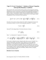
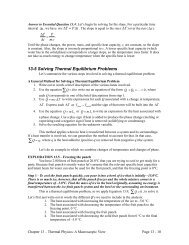
Rotating <strong>Crystal</strong> Method<br />
This method uses a monochromatic beam <strong>of</strong> x-ray from a source that is fixed. The<br />
incident angle, , is variable by rotating the crystal orientation. (Note that is the angle<br />
between the incident x-ray and the crystal plane, not the sample surface (Fig. 3.23)) The<br />
detector is moved (by rotating the detector arm) to intercept the diffracted beam. Once<br />
the diffracted beam is found, is determined to be a half <strong>of</strong> the angle between the<br />
incident x-ray and the detector orientation, in accordance to the Bragg diffraction law.<br />
The single crystal is rotated by a precision goniometer to bring sets <strong>of</strong> atomic planes into<br />
positions for the Bragg diffraction during the measurement. The axis <strong>of</strong> rotation <strong>of</strong> the<br />
detector arm is perpendicular to both the incident and reflected beams. A diffraction spot<br />
is detected when a set <strong>of</strong> crystal planes with the appropriate inter-planar separation, d,<br />
satisfies the Bragg condition. The Ewald construction <strong>of</strong> Fig. 3.23 illustrates the principle<br />
<strong>of</strong> operation.<br />
To detector<br />
(rotatable)<br />
<br />
collimator<br />
<br />
2<br />
collimator<br />
Sample (rotatable)<br />
Fig. 3.22 Schematic diagram for the setup <strong>of</strong> the rotating crystal method.<br />
Fig. 3.23 The Ewald construction for the<br />
rotating-crystal method. For simplicity a case is<br />
shown in which the incident wavevector lies in a<br />
lattice plane. The concentric circles are the orbits<br />
swept out under the rotation by the reciprocal<br />
lattice vectors lying in the plane perpendicular to<br />
the axis containing k. Each intersection <strong>of</strong> such a<br />
circle with the Ewald sphere gives the<br />
wavevector <strong>of</strong> a Bragg reflected ray.<br />
(Additional) Bragg reflected wavevectors<br />
associated with reciprocal lattice vectors in other<br />
planes are not shown. (From A&M)<br />
17
![arXiv:1303.7274v2 [physics.soc-ph] 27 Aug 2013 - Boston University ...](https://img.yumpu.com/51679664/1/190x245/arxiv13037274v2-physicssoc-ph-27-aug-2013-boston-university-.jpg?quality=85)