The Nordic IFRA CLASS RULES FOR THE IF-BOAT 1997 Issue ...
The Nordic IFRA CLASS RULES FOR THE IF-BOAT 1997 Issue ...
The Nordic IFRA CLASS RULES FOR THE IF-BOAT 1997 Issue ...

Create successful ePaper yourself
Turn your PDF publications into a flip-book with our unique Google optimized e-Paper software.
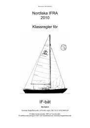
<strong>The</strong> <strong>Nordic</strong> <strong><strong>IF</strong>RA</strong><br />
<strong>CLASS</strong> <strong>RULES</strong> <strong>FOR</strong> <strong>THE</strong> <strong>IF</strong>-<strong>BOAT</strong> <strong>1997</strong><br />
<strong>Issue</strong> 1998-02-18<br />
Translated by Marek Janiec on 1999-01-07<br />
Authority: <strong>The</strong> Swedish Sailing Federation, af Pontins väg 6, S-115 21<br />
STOCKHOLM<br />
<strong>The</strong> <strong>IF</strong>-boat was designed 1967 by Tord Sundén and it was adopted as a national<br />
One Design Class in 1970 by <strong>The</strong> Swedish Sailing Federation.<br />
SECTION A - FUNDAMENTAL <strong>RULES</strong><br />
A.1 One Design Clause<br />
A.2 Abbreviations<br />
A.3 Authority<br />
A.4 Language<br />
A.5 Class Rules and their Interpretations<br />
SECTION B - ORGANISATION<br />
B.1 Administration of the class<br />
B.2 Sail Numbers<br />
B.3 Measurers<br />
B.4 Measurement Certificates<br />
B.5 Change of Ownership<br />
B.6 Amendments to Class Rules<br />
SECTION C - CONDITIONS <strong>FOR</strong> RACING<br />
C.1 Equipment<br />
C.2 Total weight<br />
C.3 Sails and Setting of Sails<br />
C.4 Crew<br />
C.5 Advertising<br />
C.6 Certificate<br />
C.7 Membership<br />
SECTION D - HULL<br />
D.1 Builders<br />
D.2 Measurement and Certification<br />
D.3 Hull Shell<br />
D.4 Deck<br />
D.5 Hull Additions<br />
D.6 Complete Hull<br />
D.7 Accommodations<br />
SECTION E - RUDDER AND TILLER<br />
E.1 Manufacturers<br />
E.2 Measurement and Certification<br />
E.3 Design<br />
E.4 Additional Rules<br />
No license: PDF produced by PStill (c) F. Siegert - http://www.this.net/~frank/pstill.html
SECTION F - RIG<br />
F.1 Manufacturers<br />
F.2 Measurement and Certification<br />
F.3 Mast<br />
F.4 Boom<br />
F.5 Spinnaker Pole<br />
F.6 Standing Rig<br />
F.7 Running Rig<br />
F.8 Additional Rules<br />
SECTION G - SAILS<br />
G.1 Sailmakers<br />
G.2 Measurement and Certification<br />
G.3 Mainsail<br />
G.4 Foresail Genoa<br />
G.5 Foresail Jib<br />
G.6 Spinnaker<br />
G.7 Identification Marks<br />
SECTION H - DRAWINGS<br />
No license: PDF produced by PStill (c) F. Siegert - http://www.this.net/~frank/pstill.html
SECTION A - FUNDAMENTAL <strong>RULES</strong><br />
A.1 One Design Clause<br />
A.1.1<br />
Anything not specifically permitted by these class rules is PROHIBITED.<br />
A.2 Abbreviations<br />
SSF<br />
ISAF<br />
MNA<br />
N<strong>IF</strong><br />
MF<br />
MC<br />
RRS<br />
<strong><strong>IF</strong>RA</strong><br />
Swedish Sailing Federation<br />
International Sailing Federation<br />
ISAF Member National Authority<br />
National <strong>IF</strong>-boat association<br />
Measurement Form<br />
Measurement Certificate<br />
Racing Rules of Sailing<br />
<strong>Nordic</strong> <strong>IF</strong>-boat Racing Association, an organisation for cooperation<br />
between the N<strong>IF</strong>s in Denmark, Norway and Sweden<br />
A.3 Authority<br />
A.3.1<br />
A.3.2<br />
<strong>The</strong> highest authority for interpretation of these class rules is the<br />
SSF, which, via the Swedish <strong>IF</strong>-boat Association, shall co-operate<br />
with the <strong><strong>IF</strong>RA</strong> in all class rule matters.<br />
Neither an MNA, through an MNA recognised measurer, the N<strong>IF</strong> or the <strong><strong>IF</strong>RA</strong> is<br />
under any legal responsibility in respect of these class rules or<br />
measurements performed, and no claims arising from those will be<br />
accepted.<br />
A.3.3 <strong>The</strong>se class rules shall be approved by the corresponding MNA to be valid in a country.<br />
A.4 Language<br />
A.4.1<br />
A.4.2<br />
<strong>The</strong> official language of the class is Swedish, and in case of dispute<br />
over translations the Swedish text shall prevail.<br />
<strong>The</strong> word "shall" is mandatory and the word "may" is permissible.<br />
A.5 Class Rules and their Interpretations<br />
A.5.1<br />
A.5.2<br />
A.5.3<br />
Whenever the words "class rules" are used in these rules, they shall<br />
be understood as including the approved drawings and the MF.<br />
In case of any discrepancy between the text of the class rules,<br />
approved drawings and building specifications, in the first instance<br />
the text shall prevail. Secondarily the matter shall be referred to the SSF.<br />
All interpretations shall be made by the SSF, which shall ask the<br />
<strong><strong>IF</strong>RA</strong> for advise. <strong>The</strong> only exception is the interpretation at an<br />
event, made by a Racing Authority regarding a measurement protest.<br />
Such interpretations shall be forwarded to the SSF as soon as<br />
possible.<br />
No license: PDF produced by PStill (c) F. Siegert - http://www.this.net/~frank/pstill.html
SECTION B - ORGANISATION<br />
B.1 Administration of the Class<br />
B.1.1<br />
B.1.2<br />
<strong>The</strong> MNA may delegate its functions, as stated in these class rules, to a N<strong>IF</strong>.<br />
In countries, where there is no MNA, its functions as stated in these<br />
class rules, shall be carried out by the Swedish <strong>IF</strong>-boat Association,<br />
which may delegate the administration to the N<strong>IF</strong>.<br />
B.2 Sail Numbers<br />
B.2.1<br />
B.2.2<br />
Sail numbers shall be issued by the MNA in co-operation with the<br />
N<strong>IF</strong>.<br />
<strong>The</strong> sail number shall be permanently marked on the mast bulkhead.<br />
B.3 Measurers<br />
B.3.1<br />
B.3.2<br />
B.3.3<br />
A measurer shall be recognised by his or her MNA.<br />
A measurer shall not measure any part owned, designed or built by<br />
himself, or in which he is an interested party or has a vested<br />
interest, except where permitted by these class rules.<br />
If a measurer is in any doubt as to conformity with the class<br />
rules, he shall consult the SSF before signing an MF or attaching an<br />
official certification mark.<br />
B.4 Measurement Certificate<br />
B.4.1<br />
B.4.2<br />
B.4.3<br />
In order to receive an MC , the owner shall send a completed MF to<br />
the MNA together with the registration fee, if any. <strong>The</strong> completed MF<br />
shall be signed by a recognised measurer who fulfils paragraph B.3.<br />
Upon receipt of a correctly completed and signed MF, the MNA may<br />
issue an MC. A copy of the MC shall be kept by the MNA.<br />
Notwithstanding anything contained in these class rules, the MNA may<br />
withdraw an MC. Upon request an owner is obliged to return the MC to<br />
the MNA.<br />
B.5 Change of Ownership<br />
B.5.1<br />
Change of ownership invalidates the MC, but it is not necessary to<br />
re-measure the boat. <strong>The</strong> new owner shall apply to the MNA for a new<br />
MC, returning the old MC together with the re-registration fee, if<br />
any. <strong>The</strong>n a new MC may be issued to the new owner.<br />
B.6 Amendments to Class Rules<br />
B.6.1<br />
B.6.2<br />
Amendments or additions to the class rules shall be proposed to <strong><strong>IF</strong>RA</strong><br />
by a N<strong>IF</strong>. After adoption of the proposal by the <strong><strong>IF</strong>RA</strong>, the amendments<br />
or additions shall be passed to SSF for approval, and then the decision<br />
is taken in the different N<strong>IF</strong>s respectively.<br />
To be valid in a country in which the <strong>IF</strong>-boat is adopted as a<br />
national One design Class, amendments and additions to these class<br />
rules shall be approved by the corresponding MNA.<br />
No license: PDF produced by PStill (c) F. Siegert - http://www.this.net/~frank/pstill.html
SECTION C - CONDITIONS <strong>FOR</strong> RACING<br />
C.1 Equipment<br />
C.1.1<br />
C.1.2<br />
GENERAL<br />
Only such equipment that is clearly permitted in these class rules may be<br />
used.<br />
MANDATORY EQUIPMENT<br />
.a 1 anchor with a minimum weight of 7.5 kg<br />
.b 1 anchor rope, a minimum length of 30m and with a minimum diameter of 12mm or<br />
equivalent properties and of sufficient strength for a sailboat of 2.3 tonnes.<br />
.c 1 paddle, length about 1200 mm.<br />
.d 2 towing ropes, each with the minimum length of 10 m and a minimum diameter<br />
of 10 mm, strong enough for a sailboat of 2.3 tons.<br />
.e Life jackets for all crew members.<br />
.f 1 bucket or hand operated bilge pump.<br />
.g 1 stove with one- or two burners.<br />
.h 1 cutlery box, size about 250 x 300 mm.<br />
.i Cushions for the berths. <strong>The</strong> cushions are to be designed for use on board an <strong>IF</strong>-boat.<br />
C.1.3<br />
OPTIONAL INSTRUMENTS<br />
.a Radio receivers<br />
.b Binoculars<br />
.c Clocks and watches<br />
.d Non-electronic wind direction indicator<br />
.e Magnetic compasses<br />
C.1.4<br />
O<strong>THE</strong>R OPTIONAL EQUIPMENT<br />
.a Battery<br />
.b Tools<br />
.c Outboard motor<br />
.d Other loose equipment, e.g. personal equipment, camping<br />
equipment etc.<br />
C.1.5<br />
LIMITATIONS<br />
.a In a One Design "race round the buoys" (Translator's remark: i.e. the<br />
rounding marks are movable and the race is directed in the<br />
wind direction) not more than 2 mainsails, 2 foresails and 2<br />
spinnakers shall be on board. <strong>The</strong> two spinnakers shall be clearly<br />
different in colour or pattern.<br />
Only one spinnaker and one mainsail shall be used in one<br />
single race.<br />
Maximum 2 sets of sails (= 2 mainsails +2 foresails + 2<br />
spinnakers) may be brought for measurement and no other<br />
sails shall be used during the regatta.<br />
.b During a "race round the buoys" an optional outboard motor<br />
shall not be fitted to the stern.<br />
.c Any electronic and hydraulic equipment is prohibited.<br />
.d In handicap races to the DH-rule (Danish Handicap Rule) it is,<br />
notwithstanding the provisions of paragraph D.6.5.b, fitted toe<br />
straps are not permitted.<br />
No license: PDF produced by PStill (c) F. Siegert - http://www.this.net/~frank/pstill.html
C.1.6<br />
ADDITIONAL <strong>RULES</strong><br />
.a In a One Design "race round the buoys" no other equipment is allowed to<br />
be used except of equipment mentioned in paragraphs C.1.2 to C.1.5 . If<br />
there is other equipment on board, it shall be made inoperable or out of<br />
function in a way that cannot be questioned.<br />
.b For other types of racing (distance, passage and/ore handicap racing)<br />
the use of equipment and sails are only regulated by the racing<br />
instructions, the regulations of the current handicap rule and<br />
the RRS.<br />
.c Equipment and sails may be stored where desired.<br />
C.2 Total Weight<br />
C.2.1<br />
<strong>The</strong> total weight of the boat including accommodation and permanent<br />
fittings but excluding sails, towing and anchoring equipment, sheets<br />
and loose fittings shall not be less than 2150 kg. Corrector weights,<br />
if any, shall be permanently fitted onto the underside of the deck<br />
with 2/3 of the total weight forward and 1/3 aft of the cabin<br />
bulkhead, situated at the forward end of the cockpit.<br />
C.3 Sails and Setting of Sails<br />
C.3.1<br />
C.3.2<br />
C.3.3<br />
C.3.4<br />
C.3.5<br />
When the mainsail is set, its highest visible point at the head shall<br />
be lower than the lower edge of the mast upper spar band, and the<br />
leech or its extension shall cut the upper side of the boom inside<br />
the inner edge of the boom spar band.<br />
When a furling foresail is set, it is to be used either wholly rolled<br />
out or wholly rolled in.<br />
A foresail that is not a spinnaker or furling sail shall be attached<br />
to the forestay along the length of the luff by only hooks or thin<br />
bands. A profile or similar device may not be used for attaching the sail to<br />
the forestay.<br />
A mainsail shall not be used with a loose foot.<br />
Only such sails that have been fundamentally measured as per rule<br />
B.3.1 or G.2.2 may be used when racing.<br />
C.4 Crew<br />
C.4.1 In a One Design "course race" the crew shall consist of 2 or 3<br />
persons. <strong>The</strong> number of crew shall remain the same throughout a<br />
regatta.<br />
C.4.2<br />
For any other type of race the number of crew is optional.<br />
C.5 Advertising<br />
C.5.1<br />
Advertising as per RRS is permitted.<br />
C.6 Certificate<br />
C.6.1<br />
<strong>The</strong> boat shall have an MC, issued in the name of the owner.<br />
No license: PDF produced by PStill (c) F. Siegert - http://www.this.net/~frank/pstill.html
C.7 Membership<br />
C.7.1<br />
In championship races the owner or the owner's representative shall<br />
be a member of the N<strong>IF</strong>, or if there is no N<strong>IF</strong> in the country, a<br />
member of the Swedish <strong>IF</strong>-boat Association.<br />
SECTION D - HULL<br />
D.1 Builders<br />
D.1.1<br />
A boat builder shall be licensed by the SSF.<br />
D.2 Measurement and Certification<br />
D.2.1<br />
.a <strong>The</strong> hull and permanently fitted accommodation shall be in<br />
accordance with the rules in force at the time for the first<br />
fundamental measurement of the boat with the exception that<br />
amendments and repairs shall be in accordance with current<br />
rules.<br />
.b <strong>The</strong> hull form shall not be altered in any case, and intentional<br />
variations within the given tolerances are prohibited.<br />
.c <strong>The</strong> hull form is checked by official hull templates or by a<br />
hull measuring machine. <strong>The</strong> N<strong>IF</strong> or the MNA may order check<br />
dimensions of hull, deck and rudder.<br />
D.2.2<br />
D.2.3<br />
Dimensions shall be measured in accordance with the ISAF¨s (IYRU´s)<br />
measurement instructions 1986, except where mentioned otherwise in<br />
this section.<br />
If a hull has been significantly changed by rebuilding or repair, the<br />
measurement certificate automatically becomes invalid. A new<br />
measurement certificate may be issued after fundamental remeasurement<br />
of the relevant parts.<br />
D.3 Hull Shell<br />
D.3.1<br />
D.3.2<br />
MATERIAL<br />
Manually laminated Glass-fibre Reinforced Polyester (GRP).<br />
DIMENSIONS<br />
.a See drawings 1223A, 1223B and 1460<br />
.b Tolerances:<br />
Length over all<br />
+/- 10 mm<br />
Design Water Line<br />
+/- 10 mm<br />
Beam section 1 -- 16 +/- 1 %<br />
Freeboard +/- 1 %<br />
Draft +/- 1 %<br />
Radius grater than 25mm +/- 2 mm<br />
Radius less than 25 mm +/- 1 mm<br />
D.3.3<br />
WEIGHT<br />
See drawing 1460<br />
No license: PDF produced by PStill (c) F. Siegert - http://www.this.net/~frank/pstill.html
D.4 Deck<br />
D.4.1<br />
D.4.2<br />
D.4.3<br />
MATERIAL<br />
Water resistant marine plywood as sandwich material in reinforcements.<br />
DIMENSIONS<br />
See drawings 1223A, 1229B and 1460<br />
WEIGHT<br />
See drawing 1460<br />
D.5 Hull Additions<br />
D.5.1<br />
D.5.2<br />
BULKHEADS<br />
See drawing 1460<br />
BALLAST KEEL<br />
.a Cast iron built into the hull.<br />
.b <strong>The</strong> weight of the cast iron shall be 1250 kg +/- 10 kg.<br />
.c <strong>The</strong> dimensions shall be in accordance with an official mould.<br />
See drawings 1460, 1223A and 1223B.<br />
D.6 Complete Hull<br />
D.6.1<br />
D.6.2<br />
D.6.3<br />
MOTOR WELL<br />
<strong>The</strong> motor well is optional. If the motor well is missing, a corrector<br />
weight of minimum 3.75 kg shall be fitted onto the lazarette floor at<br />
the place corresponding to centre of the motor well, i.e. 200 mm from<br />
centre line to port side and 700 mm forward the centre of the stern<br />
at deck height.<br />
COCKPIT<br />
<strong>The</strong> cockpit is to be self-draining.<br />
REIN<strong>FOR</strong>CEMENTS<br />
.a <strong>The</strong> reinforcements at the stem, the berth fittings, the<br />
forestay fitting, for fitting the accommodation and inside the<br />
shell and the deck shall be in accordance with drawing 1460.<br />
.b Reinforcements at the chain plates, so called "knees",<br />
constructed as per drawing 1965-2, are permitted. <strong>The</strong>y shall be<br />
fundamentally measured and a new MC including a special note<br />
shall be issued.<br />
D.6.4<br />
FITTINGS<br />
Fittings are optional with the exception that the stem plate and the<br />
stem rail is always to be present.<br />
No license: PDF produced by PStill (c) F. Siegert - http://www.this.net/~frank/pstill.html
D.6.5<br />
O<strong>THE</strong>RS<br />
.a Hand holds on deck are permitted<br />
.b Toe straps may be used. <strong>The</strong>y shall be fitted to the inside<br />
of the cockpit and shall not be possible for them to be stretched<br />
outside the cockpit coaming<br />
.c No other equipment than in position .b above shall be used<br />
for keeping the weight of the crew outside the boat.<br />
.d Epoxy plastics and vinyl-esters may be used as glue, for the purposes of<br />
repair and for exterior hull layer.<br />
.e Filling up or grinding down the outboard parts of the self<br />
drain hull fittings is prohibited, as well as mounting of "flaps"<br />
over the slot between rudder and hull.<br />
D.7 Accommodations<br />
D.7.1<br />
MINIMUM STANDARD ACCOMMODATIONS<br />
.a <strong>The</strong> minimum standard for accommodations is as follows:<br />
4 solid berths. Length each min.1800 mm. Maximum width min. 600 mm.<br />
1 galley, length min 575 mm.<br />
1 hanging locker with door or solid front, length min 350 mm.<br />
4 lockers under the side decks. Total length min 2000 mm,<br />
height min 200 mm.<br />
Floor in the cabin and in the space underneath the cockpit.<br />
.b Materials for the accommodations shall be homogenous wood or<br />
water resistant marine plywood, min thickness 6 mm. Materials<br />
for decor and the exterior layer are optional.<br />
.c Any accommodations exceeding the minimum, specified in position<br />
.a above is permitted.<br />
D.7.2<br />
MOD<strong>IF</strong>IED STANDARD ACCOMMODATIONS<br />
a. <strong>The</strong> accommodations as per D.7.1.a may be modified, but the<br />
modification shall not be made with the purpose of changing the<br />
boat´s weight, weight distribution or change the boat's character of a<br />
cruiser/racer, and shall not considerably detract from the possibility for a<br />
racing crew to live on board.<br />
.b All modifications of the minimum accommodations in accordance<br />
with D.7.1.a shall be approved by the N<strong>IF</strong>. <strong>The</strong> modification<br />
shall be described on an MF, which shall be signed by an<br />
official measurer. A new MC shall be issued by the MNA,<br />
containing a short description of the modifications made.<br />
No license: PDF produced by PStill (c) F. Siegert - http://www.this.net/~frank/pstill.html
SECTION E - RUDDER AND TILLER<br />
E.1 Manufacturers<br />
E.1.1<br />
<strong>The</strong> choice of a rudder manufacturer is optional.<br />
E.2 Measurement and Certification<br />
E.2.1<br />
E.2.2<br />
E.2.3<br />
E.2.4<br />
E.2.5<br />
<strong>The</strong> rudder shall be in accordance with the rules in force at the time<br />
for the first fundamental measurement of the boat with the exception<br />
that amendments and repairs shall be in accordance with current<br />
rules.<br />
Official moulds for rudder manufacturing shall be fundamentally<br />
measured by an official measurer and shall be approved by the <strong><strong>IF</strong>RA</strong>.<br />
A rudder shall only be fundamentally measured by an official<br />
measurer.<br />
An official certification mark shall, where it is applicable, be<br />
applied, showing the date for the fundamental measurement.<br />
A rudder, which has been significantly modified or repaired, shall be<br />
re-measured, and the measurer shall apply a new official<br />
certification mark, which shows the new date for fundamental<br />
measurement.<br />
E.3 Design<br />
E.3.1<br />
MATERIAL AND CONSTRUCTION<br />
.a <strong>The</strong> rudder shall be made from GRP sandwich. <strong>The</strong> filling<br />
material shall be divinycell, termanto or similar, or marine<br />
plywood. <strong>The</strong> rudder shall not include any greater empty<br />
hollows.<br />
.b <strong>The</strong> tiller shall be made from homogenous or laminated wood.<br />
E.3.2<br />
DIMENSIONS<br />
.a See drawing 1231-2. <strong>The</strong> radius of the trailing edge shall not,<br />
at any position, be less than 5 mm. <strong>The</strong> tolerance for the rudder's<br />
width dimensions are +/- 5 mm. <strong>The</strong> axis of the tiller shall be<br />
placed 2720 +/- 25 mm above the lower edge of the rudder.<br />
.b Rudders shall be manufactured in an official mould, that has been<br />
previously verified by an official measurer and<br />
approved by the <strong><strong>IF</strong>RA</strong>. A rudder manufactured in such a way shall<br />
be identified by markings inside the mould and on the<br />
rudder.<br />
.c Rudders may also be manufactured in other ways than described i .b, but in<br />
accordance with drawing and material description on drawing<br />
1231-2. In such cases the rudder shall be fundamentally<br />
measured by an official measurer, and the measurer shall apply<br />
an official certification mark or stamp, that shows the date<br />
for the fundamental measurement.<br />
.d <strong>The</strong> dimensions of the tiller are optional.<br />
No license: PDF produced by PStill (c) F. Siegert - http://www.this.net/~frank/pstill.html
E.3.3<br />
FITTINGS<br />
.a <strong>The</strong> rudder pintails shall be made from brass, bronze or steel.<br />
<strong>The</strong>ir positions shall be adjusted to fit the gudgeons mounted to<br />
the boat.<br />
.b <strong>The</strong> rudder plates shall be made from steel or brass. <strong>The</strong><br />
dimensions of the plates are optional.<br />
.c <strong>The</strong> tiller extension is optional.<br />
E.3.4<br />
WEIGHT<br />
<strong>The</strong> weight including permanent fittings but excluding tiller shall be<br />
minimum 22.0 kg.<br />
E.4 Additional Rules<br />
E.4.1<br />
Epoxy plastics and vinyl-esters may be used as glue, for the purpose of<br />
repair and for the exterior layer.<br />
SECTION F - RIG<br />
F.1 Manufacturers<br />
F.1.1<br />
<strong>The</strong> choice of manufacturer for spars and rig is optional.<br />
F.2 Measurement and Certification<br />
F.2.1<br />
F.2.2<br />
F.2.3<br />
F.2.4<br />
F.2.5<br />
F.2.6<br />
F.2.7<br />
<strong>The</strong> spars and rig shall be in accordance with the rules in force at<br />
the time for the first fundamental measurement of the boat with the<br />
exception that amendments and repairs shall be in accordance with<br />
current rules.<br />
A manufacturer may be issued a certification license from the <strong><strong>IF</strong>RA</strong>.<br />
A manufacturer holding a certification license is allowed to<br />
fundamentally measure own manufactured spars. Other spars shall be<br />
fundamentally measured by an official measurer.<br />
Dimensions shall be measured in accordance with the ISAF's (IYRU's)<br />
measurement instructions 1986, except when mentioned otherwise in<br />
this section<br />
On the mast and the boom there shall be applied the manufacturer's<br />
mark and serial number, alternatively an official measurers sticker,<br />
showing the date for the fundamental measurement<br />
Significantly modified or repaired spars shall be re-measured, and the<br />
measurer shall apply a new official certification mark, which shows<br />
the new date for fundamental measurement.<br />
Existing spar bands shall be well contrasting against the spar and<br />
have minimum with of 20 mm.<br />
No license: PDF produced by PStill (c) F. Siegert - http://www.this.net/~frank/pstill.html
F.3 Mast<br />
F.3.1<br />
F.3.2<br />
MATERIAL<br />
Aluminium alloy<br />
CONSTRUCTION<br />
.a <strong>The</strong> cross section shape shall be oval or drop formed.<br />
.b <strong>The</strong> mast shall have a permanent track for the luff of the<br />
mainsail. <strong>The</strong> track shall be a part of the mast section. An<br />
external sail track is only permitted for original masts on<br />
older boats (year of building 1967).<br />
.c <strong>The</strong> cross section shape shall be the same along the entire<br />
length of the mast.<br />
.d Permanently bent or rotating masts are prohibited, but due to<br />
distortion a curvature between the upper and lower spar bands<br />
of max. 25 mm is permitted<br />
.e Dimensions Min mm Max mm<br />
Transverse cross section 75 92<br />
Longitudinal cross section 120 127<br />
<strong>The</strong> upper edge of the lower<br />
Spar band above the coach roof 695 705<br />
<strong>The</strong> lower edge of the middle<br />
spar band above the upper edge<br />
of the lower spar band ---- 7160<br />
<strong>The</strong> lower edge of the upper<br />
spar band above the upper edge<br />
of the lower spar band ---- 8750<br />
Spinnaker hoist height above the<br />
lower edge of the middle spar band ---- 470<br />
Extension of the permanent fitting<br />
for the spinnaker halyard block<br />
forward the fore edge of the mast ---- 50<br />
<strong>The</strong> height of the fitting for the<br />
spinnaker pole above the coach roof 1) ---- 1540<br />
1) <strong>The</strong> dimension is to be measured to the centre of the fitting<br />
F.3.3<br />
FITTINGS<br />
.a <strong>The</strong>re shall be a permanent stop preventing the boom from being<br />
positioned in such a way that its upper edge is below the upper<br />
edge of the lower spar band.<br />
.b A rail for a movable fitting for the spinnaker pole is<br />
permitted, but if it is fitted, there shall be a permanent stop preventing<br />
the fitting from moving higher than permissible.<br />
No license: PDF produced by PStill (c) F. Siegert - http://www.this.net/~frank/pstill.html
F.3.4<br />
WEIGHTS AND CENTRES OF GRAVITY<br />
.a <strong>The</strong> spar weight shall be minimum 2.2 kg/m<br />
.b <strong>The</strong> total weight including all normal permanent fittings,<br />
excluding standing and running rigging shall be minimum 23.0<br />
kg, and the centre of gravity position shall be minimum 3500 mm<br />
above the upper edge of the lower spar band.<br />
F.3.5<br />
POSITION<br />
.a <strong>The</strong> mast shall stand on the centre line and on a permanent<br />
fitting. <strong>The</strong> fitting shall have sufficient bearing area and<br />
stiffness so that the compression of the mast will not cause<br />
any local deformation of the coach roof.<br />
.b <strong>The</strong> distance from the most forward<br />
point of the stem to the intersection<br />
point between the coach roof and the<br />
line along the forward edge of the<br />
mast. Min mm Max mm<br />
2935 2955<br />
(<strong>The</strong> extreme forward point is defined as the forward point of an undamaged stem fitting)<br />
F.4 Boom<br />
F.4.1<br />
F.4.2<br />
MATERIAL<br />
Aluminium alloy<br />
CONSTRUCTION<br />
.a <strong>The</strong> shape of the cross section is optional.<br />
.b <strong>The</strong> boom shall have a permanent track for the foot of the<br />
mainsail.<br />
.c <strong>The</strong> cross section shall be the same along the entire length of<br />
the boom.<br />
.d A permanently bent boom is prohibited, but due to form change a<br />
curvature between the fore end of the boom and the boom spar<br />
band of max. 15 mm is permitted<br />
.e Dimensions<br />
Min mm Max mm<br />
Transverse 55 70<br />
Vertical 75 95<br />
<strong>The</strong> forward edge of the spar<br />
band from the aft edge of the mast ---- 3400<br />
F.4.3<br />
FITTINGS<br />
Optional except that a solid boom vang with a function to lift the boom<br />
and a roller reef is prohibited.<br />
No license: PDF produced by PStill (c) F. Siegert - http://www.this.net/~frank/pstill.html
F.4.5<br />
WEIGHTS<br />
.a <strong>The</strong> spar weight shall be minimum 1.30 kg/m.<br />
.b <strong>The</strong> total weight including all normal permanent fittings shall<br />
be minimum 5.0 kg.<br />
F.5 Spinnaker Pole<br />
F.5.1<br />
F.5.2<br />
MATERIAL<br />
Aluminium alloy , steel or wood.<br />
DIMENSIONS<br />
.a With its end fitting attached to the mast and when<br />
extended maximally in any direction, the outermost<br />
point of the spinnaker pole is to be max. 2550 mm<br />
from the line along the fore edge of the mast.<br />
.b <strong>The</strong> spar cross section dimensions and section shape are<br />
optional.<br />
F.5.3<br />
F.5.5<br />
FITTINGS<br />
Optional<br />
WEIGHT<br />
Optional<br />
F.6 Standing Rigging<br />
F.6.1<br />
MATERIAL<br />
.a Steel wire for shrouds and stays.<br />
.b Steel or aluminium for spreaders.<br />
F.6.2<br />
CONSTRUCTION<br />
.a <strong>The</strong> standing rigging shall consist of:<br />
-1 pair of upper shrouds, min 5 mm diameter<br />
-1 pair of lower shrouds, min 4 mm diameter<br />
-1 permanent forestay, min 5 mm diameter<br />
-1 adjustable backstay, min 3 mm diameter<br />
-1 pair of spreaders of swinging type, swept backwards<br />
No license: PDF produced by PStill (c) F. Siegert - http://www.this.net/~frank/pstill.html
.b Dimensions<br />
Mountings onto the mast above the upper edge of the lower spar<br />
band:<br />
Min mm Max mm<br />
Spreaders 3125 3175<br />
Upper shrouds 7125 7225<br />
Lower shrouds 3038 3138<br />
<strong>The</strong> extension of the forestay shall intersect the mast below<br />
the lower edge of the middle spar band.<br />
(All dimensions shall be measured in direction along the mast<br />
to the intersection point between the mast and a line through<br />
the centre of stay, shroud and spreader)<br />
Mountings onto the deck in longitudinal direction<br />
Min mm Max mm<br />
Foresail fitting, extended to deck<br />
parallel to the forestay, forward<br />
of the line along the forward edge of<br />
the mast ---- 2525 *)<br />
Upper shrouds ( in positions marked<br />
for the purpose) aft of the line along<br />
the forward edge of the mast 445 475<br />
Lower shrouds (in positions marked for<br />
the purpose) aft of the line along the<br />
forward edge of the mast 345 375<br />
<strong>The</strong> distance between the upper and<br />
lower shroud fittings 90 110<br />
<strong>The</strong> distance between the forestay and<br />
foresail fittings and with:<br />
Min mm Max mm<br />
-the foresail attached to the<br />
forestay by piston hanks or similar ---- 35<br />
-a furling foresail with only the top<br />
swivel attached to the forestay ---- 75<br />
(All dimensions are projections on the centre line of the boat<br />
and are referred to an imaginary line through the centre of the<br />
fitting respectively)<br />
*) This dimension may be checked by measuring to the intersection<br />
point between the coach roof and the imaginary line along the forward<br />
edge of the mast. This point shall be at a distance of max. 2530 mm<br />
from the measured point.<br />
No license: PDF produced by PStill (c) F. Siegert - http://www.this.net/~frank/pstill.html
Mountings onto the deck in transverse direction:<br />
- <strong>The</strong> foresail fitting shall be placed on the centre line of the boat<br />
- <strong>The</strong> fittings for the upper shrouds shall be placed in positions<br />
marked for the purpose just inside the toerail.<br />
- <strong>The</strong> fittings for the lower shrouds shall be placed in<br />
positions marked for the purpose at 35 mm +/- 5mm inside the rail.<br />
Min mm<br />
Max mm<br />
<strong>The</strong> length of the spreaders from the side of the mast 755 765<br />
<strong>The</strong> distance from the imaginary line<br />
between the spreader shroud fittings<br />
and the back edge of the mast and with:<br />
-both spreaders locked in their forward<br />
position 80 170<br />
-both spreaders locked in their aft<br />
position 260 400<br />
F.7 Running Rigging<br />
F.7.1<br />
F.7.2<br />
MATERIAL<br />
Optional<br />
DIMENSIONS<br />
Optional<br />
F.8 Additional Rules<br />
F.8.1<br />
F.8.2<br />
F.8.3<br />
F.8.4<br />
Devices for the purpose of sail trimming purpose and fittings for standing and<br />
running rigging are optional.<br />
Deck and hull penetrations for standing and running rigging are only<br />
permitted for furling jib fitting, foresail cunningham and backstay.<br />
Adjustments and trimming of the rig shall only be performed by use of<br />
turnbuckle for shroud and forestay, by use of pulley and tackle for<br />
backstay and use of kicking strap/boom vang.<br />
A mast support pillar below the deck is only permitted for older<br />
boats (year of building 1967) which do not have the mast bulkhead and the<br />
forward hatch in the original shape.<br />
No license: PDF produced by PStill (c) F. Siegert - http://www.this.net/~frank/pstill.html
SECTION G - SAILS<br />
G.1 Sailmakers<br />
G.1.1<br />
<strong>The</strong> choice of sailmaker is optional.<br />
G.2 Measurement and Certification<br />
G.2.1<br />
G.2.2<br />
G.2.3<br />
G.2.4<br />
G.2.5<br />
G.2.6<br />
A sail shall be in accordance with the rules in force at the time<br />
for the first fundamental measurement except that modified sails<br />
shall be in accordance with current rules.<br />
A sailmaker holding a certification license from his MNA is allowed<br />
to fundamentally measure sails manufactured by himself and is in this<br />
respect equalised with an official measurer. Fundamental measurement<br />
of other sails shall be performed by an official measurer.<br />
Sails shall be manufactured and measured in accordance with the<br />
ISAF's EQUIPMENT <strong>RULES</strong> OF SAILING <strong>1997</strong> - 2000 (ERS) if nothing else<br />
is mentioned. Bold writing means that the dimension or item is<br />
defined in ERS.<br />
On Sails there shall, at the head or the tack, be attached a<br />
certification mark in accordance with the regulations of the MNA. <strong>The</strong><br />
date for the fundamental measurement and the signature of the<br />
official measurer, alternatively the sailmaker (who fulfils the requirements of G.2.2) shall be written<br />
on or near the certification mark.<br />
<strong>The</strong> sailmaker shall, at the head or the tack, in a non-removable way,<br />
write the weight in g/m² of the body of the sail and date and sign<br />
the sail.<br />
A sail, which is significantly modified shall be re-measured, and the<br />
official measurer or the sailmaker (who fulfils the requirements of G.2.2) shall apply a new<br />
certification mark on the sail, which shows the new date for fundamental measurement.<br />
G.3 Mainsail<br />
G.3.1<br />
CONSTRUCTION.<br />
.a <strong>The</strong> construction shall be soft sail, single ply sail.<br />
.b <strong>The</strong> body of the sail shall only consist of woven ply of the<br />
same ply weight except for an area within a distance of max.<br />
250 mm from the foot, which may have different ply weight than<br />
the rest of the sail. <strong>The</strong> ply fibres shall be of polyester.<br />
.c <strong>The</strong> sail shall have 4 batten pockets. <strong>The</strong> batten pockets shall<br />
intersect the leech of the sail in approximately equal parts.<br />
.d <strong>The</strong> following are permitted: stitching, glues, tapes, bolt<br />
ropes, corner eyes, headboard with fixings, Cunningham eye/<br />
pulley, batten pocket elastic, batten pocket end caps, batten<br />
pocket "burr" bands, mast and boom slides, leech line with<br />
cleat, windows, sailmaker label, guarantee label, royalty<br />
label, sail button, tell tales, reef eyes, sail shape indicator<br />
stripes.<br />
No license: PDF produced by PStill (c) F. Siegert - http://www.this.net/~frank/pstill.html
G.3.2<br />
DIMENSIONS<br />
Minimum<br />
Maximum<br />
Leech length ----- 9330 mm<br />
Quarter width ----- free<br />
Half width ----- 2020 mm<br />
Three-quarter width ----- 1120 mm<br />
Top width ----- 140 mm<br />
Headboard width ----- 120 mm<br />
Weight of the ply of the body of the sail *) 250 g/m² -----<br />
Primary reinforcements ----- 600 mm<br />
Secondary reinforcements ----- free<br />
Tabling widths ----- free<br />
Seam widths ----- free<br />
Number of windows ----- 2<br />
Window area ----- 0,65 m²/each<br />
Distance from window to sail edges 150 mm -----<br />
Batten pocket lengths inside :<br />
-uppermost batten pocket (may be "long") ----- free<br />
-intermediate batten pockets ----- 1050 mm<br />
-lowermost batten pocket ----- 800 mm<br />
Batten pocket widths inside ---- 70 mm<br />
*) Within the area 250 mm from the foot the weight of the ply is<br />
optional.<br />
G.4 Foresail Genoa<br />
G.4.1<br />
CONSTRUCTION<br />
.a <strong>The</strong> construction shall be soft sail, single ply sail .<br />
.b <strong>The</strong> body of the sail shall only consist of woven ply of the<br />
same ply weight. <strong>The</strong> ply fibres shall be of polyester.<br />
.c <strong>The</strong> sail shall not have batten pockets.<br />
.d <strong>The</strong> following are permitted: stitching, glues, tapes, corner<br />
eyes, forestay hanks or bands, leech line with cleat, windows,<br />
sailmaker label, guarantee label, royalty label, sail button,<br />
tell tales, Cunningham eye, sail shape indicator stripes.<br />
.e A convex leech is prohibited.<br />
G.4.2<br />
DIMENSIONS<br />
Minimum<br />
Maximum<br />
Luff length 7600 mm 7800 mm<br />
Leech length ----- free<br />
Foot length 3800 mm 3900 mm<br />
Foot median ----- free<br />
Top with ----- 50 mm<br />
Weight of the ply of the body of the sail 190 g/m² ----<br />
Primary reinforcements ----- 600 mm<br />
Secondary reinforcements ----- free<br />
Tabling widths ----- free<br />
Seam widths ----- free<br />
Number of windows ----- 2<br />
Window area - ---- 0,65 m²/each<br />
Distance from window to sail edges 150 mm -----<br />
No license: PDF produced by PStill (c) F. Siegert - http://www.this.net/~frank/pstill.html
G.5 Foresail jib<br />
G.5.1<br />
CONSTRUCTION<br />
.a <strong>The</strong> construction shall be soft sail, single ply sail .<br />
.b <strong>The</strong> body of the sail shall only consist of woven ply of the<br />
same ply weight. <strong>The</strong> ply fibres shall be of polyester.<br />
.c <strong>The</strong> sail may have 3 batten pockets. <strong>The</strong> batten pockets shall<br />
intersect the leech of the sail in approximately equal parts.<br />
.d <strong>The</strong> following are permitted: stitching, glues, tapes, corner<br />
eyes, forestay hanks, batten pocket elastic, batten pocket end<br />
caps, batten pocket "burr" bands, leech line with cleat,<br />
windows, sailmaker label, guarantee label, royalty label, sail<br />
button, tell tales, Cunningham eye, sail shape indicator<br />
stripes.<br />
.e A convex leech is permitted.<br />
G.5.2<br />
DIMENSIONS<br />
Minimum<br />
Maximum<br />
Luff length ----- 7800 mm<br />
Leech length ----- 7150 mm<br />
Foot length ----- 2820 mm<br />
Half width ----- 1550 mm<br />
Foot median ----- free<br />
Top with ----- 50 mm<br />
Weight of the ply of the body of the sail 240 g/m² -----<br />
Primary reinforcements ----- free<br />
Secondary reinforcements ----- free<br />
Tabling widths ----- free<br />
Seam widths ----- free<br />
Number of windows ----- 2<br />
Window area ----- 0,65 m²/each<br />
Distance from window to sail edges 150 mm -----<br />
Batten pocket lengths inside 350 mm -----<br />
Batten pocket widths inside 70 mm ----<br />
G.6 Spinnaker<br />
G.6.1<br />
CONSTRUCTION<br />
.a <strong>The</strong> construction shall be soft sail, single ply sail .<br />
.b <strong>The</strong> body of the sail shall only consist of woven ply of the<br />
same ply weight. <strong>The</strong> ply fibres shall be of polyester of<br />
polyamide.<br />
.c <strong>The</strong> following are permitted: stitching, glues, tapes, corner<br />
eyes, recovery line eyes, sailmaker label, guarantee label,<br />
royalty label, sail button, tell tales, sail shape indicator<br />
stripes.<br />
No license: PDF produced by PStill (c) F. Siegert - http://www.this.net/~frank/pstill.html
G.6.2<br />
DIMENSIONS<br />
Minimum<br />
Maximum<br />
Leech length ---- 8270 mm<br />
Foot length ---- 4550 mm<br />
Foot median ---- free<br />
Half width ---- 4540 mm<br />
Weight of the ply of the body of the sail 35 g/m² -----<br />
Primary reinforcements ---- free<br />
Secondary reinforcements ---- free<br />
Tabling widths ---- free<br />
Seam widths ---- free<br />
G.7 Identification Marks<br />
G.7.1<br />
G.7.2<br />
G.7.3<br />
G.7.4<br />
<strong>The</strong> class insignia, sail numbers and national letters shall be<br />
in accordance with the RRS except when others is mentioned<br />
<strong>The</strong> class insignia shall conform to dimensions and requirements which<br />
appear on drawing 1996.<br />
National letters shall be displayed on the mainsail and spinnaker.<br />
National letters and sail number shall not be displayed on the Genoa<br />
foresail.<br />
SECTION H - DRAWINGS<br />
H.1 Enclosed Drawings<br />
Drawing Item Dated<br />
No<br />
1223A Hull drawing 15/6 1966<br />
1229B Deck drawing 19/8 1966<br />
1231-2 Rudder 10/10 1966<br />
1996 Drawing of Class Insignia 10/10 1996<br />
1460 Glass fibre armouring and deck reinforcement 11/11 1979<br />
1965-2 "Knee" reinforcement at chainplate 10/10 1996<br />
H.2 Drawings kept by <strong><strong>IF</strong>RA</strong><br />
Drawing Item Dated<br />
No<br />
1223B Hull offsets table 20/6 1966<br />
1224 Keel drawing 10/8 1966<br />
1228 Dimensional drawing of keel section 28/6 1966<br />
1230 Deck section 9/8 1966<br />
1324-1 Fore triangle base dimensions 3/3 1979<br />
1328-4 Sail drawing 9/1 1979<br />
1423-1 Rig drawing 3/3 1979<br />
No license: PDF produced by PStill (c) F. Siegert - http://www.this.net/~frank/pstill.html