3DSS128G16VB2434 - 3D Plus
3DSS128G16VB2434 - 3D Plus
3DSS128G16VB2434 - 3D Plus

You also want an ePaper? Increase the reach of your titles
YUMPU automatically turns print PDFs into web optimized ePapers that Google loves.
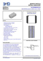
16GB µSSD MEMORY MODULE<br />
<strong><strong>3D</strong>SS128G16VB2434</strong><br />
PATA / CF / PCMCIA interface<br />
Features<br />
Storage Capacity: 16 GBytes<br />
ATA/IDE, PCMCIA 2.1 and CF 4.1 standard<br />
compatible<br />
Supports up to PIO Mode-6<br />
Supports up to Multi-Word DMA Mode-4<br />
Supports up to Ultra DMA mode-4<br />
Endurance : 2 millions W/E<br />
Hardware ECC : 4 Bytes in a 512 bytes sector<br />
Wear levelling<br />
Bad block management<br />
Flash Single-level cell technology :<br />
- Data retention : 10 years<br />
- Endurance : 100,000 W/E<br />
Data transfer to flash<br />
- Sustained read : 40 MB/s<br />
- Sustained write : 35 MB/s<br />
Power down data protection<br />
Flash write protect control<br />
SLC Nand Flash Technology<br />
5V or 3.3Vsingle power supply<br />
<br />
<br />
<br />
224 PBGA, pitch 1.27mm<br />
Operating temperature:<br />
- 0°C to +70°C<br />
- -40°C to +85°C<br />
- -55°C to +125°C<br />
Storage temperature:<br />
- -65°C to +150°C<br />
Size: 22 x 26 mm<br />
Height: 3.7 mm<br />
Mass: 4.4gr +/- 0,05<br />
Application<br />
Mass storage solution for industrial<br />
products<br />
General Description<br />
The <strong><strong>3D</strong>SS128G16VB2434</strong> is a high-density, high-performance, fully integrated, embedded flash Solid State<br />
Drive. It combines a Controller and two SLC Nand Flash integrated in a compact BGA package. This product is<br />
tolerant to shocks and supports industrial temperature for applications requiring high reliability.<br />
The endurance of the SLC FLASH is extended with controller functions of wear levelling, bad block<br />
management and hardware error correction.<br />
This product is fully compatible with the standard ATA/IDE, PCMCIA 2.1 and CF 4.1. Operation Modes<br />
supported are PC Card Memory Mode, PC Card IO Mode and True IDE Mode.<br />
Bypass capacitors and pull-up resistors are integrated inside the package, only few external components are<br />
required for a typical CF or IDE application.<br />
Thanks to the high density patented technology the memories are embedded in a small form factor package<br />
without compromising electrical or thermal performance. The <strong><strong>3D</strong>SS128G16VB2434</strong> is packaged in a BGA 224<br />
and available in commercial, industrial and military temperature range.<br />
µSSD Memory Module<br />
<strong><strong>3D</strong>SS128G16VB2434</strong><br />
<strong>3D</strong> <strong>Plus</strong> SA reserves the right to cancel product or specifications without notice<br />
<strong>3D</strong>DS-0434-REV 1- JULY 2011<br />
Page: 1/ 8
16GB µSSD MEMORY MODULE<br />
<strong><strong>3D</strong>SS128G16VB2434</strong><br />
PATA / CF / PCMCIA interface<br />
Bloc Diagram<br />
Controller<br />
32 bits RISC core<br />
RAM : 32 kBytes<br />
ROM : 20 kBytes<br />
Flash<br />
Control &<br />
ECC<br />
Flash<br />
Control &<br />
ECC<br />
Nand Flash<br />
SLC<br />
Nand Flash<br />
SLC<br />
IDE / PC card / CF interface<br />
UDMA / ATA register<br />
2.5- 3.3V<br />
Regulator<br />
Standard ATA/PC Card<br />
3.3V or 5V<br />
SSD NAND<br />
BGA Pin Configuration<br />
µSSD Memory Module<br />
<strong><strong>3D</strong>SS128G16VB2434</strong><br />
<strong>3D</strong> <strong>Plus</strong> SA reserves the right to cancel product or specifications without notice<br />
<strong>3D</strong>DS-0434-REV 1- JULY 2011<br />
Page: 2/ 8
16GB µSSD MEMORY MODULE<br />
<strong><strong>3D</strong>SS128G16VB2434</strong><br />
PATA / CF / PCMCIA interface<br />
Signal Description<br />
Signal Name Status* Description<br />
CS1#/CE2# I/PU True-IDE: Address range select for task file<br />
PC Card: Card Enable 1<br />
CSO#/CE1# I/PU True-IDE: Select Alternate Status and Device Control Registers.<br />
PC Card: Card Enable 2<br />
DMACK#/REG# I DMA Acknowledge when DMA is activated<br />
Register Select<br />
WE# I/PU True-IDE: Not used. Should be connected to VCC<br />
PC Card: Memory Write Enable,<br />
SELATA#/OE# I/PU True-IDE: Should be connected to ground<br />
PC Card: Output Enable<br />
IOWR# I/PU I/O Write Enable.<br />
STOP when DMA is activated<br />
IORD# I/PU I/O Read Enable.<br />
HSTROBE when DMA is activated<br />
CSEL# I/pu True-IDE: Cable Select. Grounded for master, Open for slave<br />
PC Card: Not used, should be connected to A25 or grounded<br />
RESET# I True-IDE: Reset active low signal<br />
PC Card: Reset active high signal<br />
A10..A0 I Address Bus. In True IDE, only A2, A1, A0 are used.<br />
The remaining address lines could be left unconnected<br />
D15..D0 I/O Data Bus<br />
IOIS16#/WP O 16-bit I/O Transfer<br />
PC Card memory mode: Write Protect<br />
DMARQ/INPACK# O True-IDE: DMA Request<br />
PC Card: Input Acknowledge<br />
INTRQ/IREQ# O True IDE: Interrupt Request, active high<br />
PC Card : Interrupt Request, active low<br />
DIAG#/STSCHG# I/O/PU True-IDE: Pass Diagnostics<br />
PC Card: Status Change<br />
DASP#/SPKR# I/O/PU True-IDE Drive Active Present<br />
PC Card: Speaker<br />
IORDY/WAIT# I/O/PU True-IDE: I/O Ready. DDMARDY when DMA is activated<br />
PC Card: Wait Signal<br />
EXT_IO PU External I/O. Reserved for specific or future use. Could be left<br />
unconnected<br />
HRESET# I/PU Hardware Reset signal of the controller.<br />
Could be left not connected.<br />
GND<br />
Host ground connection<br />
VCC<br />
Host supply connection. +5V or +3.3V<br />
* I: input, O:Output, PU:PullUp<br />
Capacity specification<br />
The spare area holds the manufacturer defect blocks. The other blocks in the spare area are used as spare<br />
blocks for defect block re-mapping for flash memory blocks that turn bad during the life of the card.<br />
Capacity Cylinders Heads Sectors/Track<br />
16 GBytes 32462 16 63<br />
µSSD Memory Module<br />
<strong><strong>3D</strong>SS128G16VB2434</strong><br />
<strong>3D</strong> <strong>Plus</strong> SA reserves the right to cancel product or specifications without notice<br />
<strong>3D</strong>DS-0434-REV 1- JULY 2011<br />
Page: 3/ 8
16GB µSSD MEMORY MODULE<br />
<strong><strong>3D</strong>SS128G16VB2434</strong><br />
PATA / CF / PCMCIA interface<br />
Absolute Maximum Ratings<br />
Operation beyond the following limits may cause module degradation, reliability reduction or permanent<br />
damage.<br />
Parameter Conditions Min Typ Max Unit<br />
Voltage on any pin Continuous -0.5 Vcc+0.5 V<br />
Storage Temperature - -65 +150 °C<br />
DC Parameters<br />
Supply Voltage Vcc=5V +/- 0.5V or 3.3V +/- 0.3V<br />
For proper operation, the module should be used within the recommended operating conditions.<br />
Parameter Symbol Conditions Min Typ Max Unit<br />
Input Low voltage Vil -0.3 +0.8 V<br />
Input High Voltage Vih 2 Vcc+0.3 V<br />
Output Low Voltage Vol At 4mA (12mA for DASP) 0.45 V<br />
Output High Voltage Voh At 1mA 2.4 V<br />
Stand By Current Isb 1.6 mA<br />
Operating Current Icc Read/Write/Erase 140 170 mA<br />
Input Output Capacitance Cio 10 pF<br />
Operating Temperature Ta com Supply Voltage 3.3V 0 +70 °C<br />
commercial<br />
Operating Temperature Ta ind Supply Voltage 3.3V -40 +85 °C<br />
industrial<br />
Operating Temperature<br />
military<br />
Ta mil Supply Voltage 3.3V -55 +125 °C<br />
Typical series termination for Ultra DMA<br />
Series termination resistors are required at both the host and the card for operation in any of the Ultra DMA<br />
modes. Only signals requiring termination are listed in this table. If a signal is not listed, series termination is<br />
not required in an Ultra DMA mode. The actual termination values should be selected to compensate for<br />
transceiver and trace impedance to match the characteristics cable impedance.<br />
Signal Host termination Device Termination<br />
IORD# 22 ohm 82 ohm<br />
IOWR# 22 ohm 82 ohm<br />
CSO#, CS1# 33 ohm 82 ohm<br />
A0, A1, A2 33 ohm 82 ohm<br />
DMACK# 22 ohm 82 ohm<br />
D15..D0 33 ohm 33 ohm<br />
DMARQ 82 ohm 22 ohm<br />
INTRQ 82 ohm 22 ohm<br />
IORDY 82 ohm 22 ohm<br />
RESET# 33 ohm 82 ohm<br />
µSSD Memory Module<br />
<strong><strong>3D</strong>SS128G16VB2434</strong><br />
<strong>3D</strong> <strong>Plus</strong> SA reserves the right to cancel product or specifications without notice<br />
<strong>3D</strong>DS-0434-REV 1- JULY 2011<br />
Page: 4/ 8
16GB µSSD MEMORY MODULE<br />
<strong><strong>3D</strong>SS128G16VB2434</strong><br />
PATA / CF / PCMCIA interface<br />
Performance<br />
Parameter Conditions Typical<br />
Host data transfert PIO mode 6 or MDMA mode 4<br />
UDMA mode 4<br />
25 MBytes/s<br />
66 MBytes/s<br />
Sustained Flash data<br />
transfert<br />
Read<br />
Write<br />
40 MBytes/s<br />
35 MBytes/s<br />
Environmental Specification<br />
Parameter Conditions Remarks<br />
Thermal Cycles<br />
Mil-std-883 Method 1010 Condition B 500 Cycles, -55°C/125°C<br />
JESD22-A104D Condition B<br />
High Temperature Storage Mil-std-883 Method 1008<br />
1000hrs, 125°C<br />
JESD22-A103C Condition A<br />
Humidity JESD22-A101 85%HR / +85°c<br />
Reference<br />
Revision Name Link<br />
11/2008 Hyperstone F4 32-bit Flash Memory<br />
Controller User’s Manual<br />
http://www.hyperstone.com/fmc_f<br />
4_en.html<br />
02/2000 Information Technology -AT Attachment<br />
with Packet Interface - 5(ATA/ATAPI-5)<br />
http://www.t13.org/Documents/Upl<br />
oadedDocuments/project/d1321r3-<br />
ATA-ATAPI-5.pdf<br />
µSSD Memory Module<br />
<strong><strong>3D</strong>SS128G16VB2434</strong><br />
<strong>3D</strong> <strong>Plus</strong> SA reserves the right to cancel product or specifications without notice<br />
<strong>3D</strong>DS-0434-REV 1- JULY 2011<br />
Page: 5/ 8
16GB µSSD MEMORY MODULE<br />
<strong><strong>3D</strong>SS128G16VB2434</strong><br />
PATA / CF / PCMCIA interface<br />
Typical Compact Flash application<br />
µSSD Memory Module<br />
<strong><strong>3D</strong>SS128G16VB2434</strong><br />
<strong>3D</strong> <strong>Plus</strong> SA reserves the right to cancel product or specifications without notice<br />
<strong>3D</strong>DS-0434-REV 1- JULY 2011<br />
Page: 6/ 8
16GB µSSD MEMORY MODULE<br />
<strong><strong>3D</strong>SS128G16VB2434</strong><br />
PATA / CF / PCMCIA interface<br />
Typical IDE application<br />
µSSD Memory Module<br />
<strong><strong>3D</strong>SS128G16VB2434</strong><br />
<strong>3D</strong> <strong>Plus</strong> SA reserves the right to cancel product or specifications without notice<br />
<strong>3D</strong>DS-0434-REV 1- JULY 2011<br />
Page: 7/ 8
16GB µSSD MEMORY MODULE<br />
<strong><strong>3D</strong>SS128G16VB2434</strong><br />
PATA / CF / PCMCIA interface<br />
Module Mechanical Drawing<br />
Part Number / Ordering Information<br />
<strong><strong>3D</strong>SS128G16VB2434</strong>-X<br />
Temperature Range<br />
C : 0°C /+70°C<br />
I : -40°C/+ 85°C<br />
M: -55°C/+125°C<br />
Main Sales Office<br />
FRANCE<br />
<strong>3D</strong> PLUS<br />
408, rue Hélène Boucher ZI.<br />
78532 BUC Cedex<br />
Tel : 33 (0)1 30 83 26 50 Fax : 33 (0)1 39 56 25 89<br />
Web : www.3d-plus.com<br />
e-mail : sales@3d-plus.com<br />
DISTRIBUTOR<br />
USA<br />
<strong>3D</strong> PLUS U.S.A, Inc<br />
6633 Eldorado Parkway<br />
Suite 420<br />
Mckinney, TX 75070<br />
Tel : (214) 733-8505 Fax : (214) 733-8506 e-mail : sales@3d-plus.com<br />
µSSD Memory Module<br />
<strong><strong>3D</strong>SS128G16VB2434</strong><br />
<strong>3D</strong> <strong>Plus</strong> SA reserves the right to cancel product or specifications without notice<br />
<strong>3D</strong>DS-0434-REV 1- JULY 2011<br />
Page: 8/ 8