Influence of the Processes Parameters on the Properties of The ...
Influence of the Processes Parameters on the Properties of The ...
Influence of the Processes Parameters on the Properties of The ...

Create successful ePaper yourself
Turn your PDF publications into a flip-book with our unique Google optimized e-Paper software.
Chapter 4.<br />
Experimental Procedures and Protocols for Analyses<br />
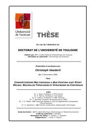
Figure 4.29: Set up <str<strong>on</strong>g>of</str<strong>on</strong>g> CT and flow chart <str<strong>on</strong>g>of</str<strong>on</strong>g> CT measurement process.<br />
4.4.1 Acquisiti<strong>on</strong><br />
<strong>The</strong> sample is rotated through 360 degrees <strong>on</strong> a precisi<strong>on</strong> turntable and a set <str<strong>on</strong>g>of</str<strong>on</strong>g> high resoluti<strong>on</strong><br />
digital radiographs are acquired at regular (typically 0.5 degree) increments. <strong>The</strong> accuracy <str<strong>on</strong>g>of</str<strong>on</strong>g> this data set<br />
determines <str<strong>on</strong>g>the</str<strong>on</strong>g> ultimate quality <str<strong>on</strong>g>of</str<strong>on</strong>g> <str<strong>on</strong>g>the</str<strong>on</strong>g> final 3D data.<br />
4.4.2 Correcti<strong>on</strong>s<br />
Each projected image from <str<strong>on</strong>g>the</str<strong>on</strong>g> data set undergoes geometric and shading correcti<strong>on</strong>, to remove<br />
spatial and intensity n<strong>on</strong> linearities introduced by <str<strong>on</strong>g>the</str<strong>on</strong>g> imaging device.<br />
4.4.3 Rec<strong>on</strong>structi<strong>on</strong><br />
By combining all <str<strong>on</strong>g>of</str<strong>on</strong>g> <str<strong>on</strong>g>the</str<strong>on</strong>g> individually corrected images and using a c<strong>on</strong>e beam back projecti<strong>on</strong><br />
technique, a geometrically correct, three dimensi<strong>on</strong>al data cloud is computed. <strong>The</strong> patented s<str<strong>on</strong>g>of</str<strong>on</strong>g>tware has a<br />
real-time viewer that shows <str<strong>on</strong>g>the</str<strong>on</strong>g> rec<strong>on</strong>structi<strong>on</strong> progressing in parallel with <str<strong>on</strong>g>the</str<strong>on</strong>g> x-ray images being captured.<br />
4.4.4 Viewing Results<br />
<strong>The</strong> CT data collecti<strong>on</strong>, rec<strong>on</strong>structi<strong>on</strong> and display are presented to <str<strong>on</strong>g>the</str<strong>on</strong>g> operator via <str<strong>on</strong>g>the</str<strong>on</strong>g> X-Tek<br />
graphical user interface. This has been developed to provide ease <str<strong>on</strong>g>of</str<strong>on</strong>g> use with <str<strong>on</strong>g>the</str<strong>on</strong>g> highest performance for<br />
systems to fit users’ budgets without compromise. <strong>The</strong> data cloud can be sliced open in any directi<strong>on</strong> to<br />
reveal internal detail, surface rendering s<str<strong>on</strong>g>of</str<strong>on</strong>g>tware similar to that used in 3D CAD systems is used to visualise<br />
<str<strong>on</strong>g>the</str<strong>on</strong>g> exposed features.<br />
4.4.5 Wide Variety <str<strong>on</strong>g>of</str<strong>on</strong>g> Post Processing<br />
<strong>The</strong> data cloud can be output as a stereo lithography file, a format accepted by most CAD<br />
packages. Once imported into a CAD system, <str<strong>on</strong>g>the</str<strong>on</strong>g> radiographic informati<strong>on</strong> can be compared directly with<br />
<str<strong>on</strong>g>the</str<strong>on</strong>g> original design file to highlight differences when checking first <str<strong>on</strong>g>of</str<strong>on</strong>g>f manufactured parts, or if <str<strong>on</strong>g>the</str<strong>on</strong>g> original<br />
design is not available, <str<strong>on</strong>g>the</str<strong>on</strong>g>n <str<strong>on</strong>g>the</str<strong>on</strong>g> radiographic data is used to create a new CAD file for rapid prototyping and<br />
reverse engineering.<br />
Micro CT <str<strong>on</strong>g>of</str<strong>on</strong>g> different scaffolds was taken from different angles and views. Slices were taken to<br />
observe <str<strong>on</strong>g>the</str<strong>on</strong>g> interc<strong>on</strong>nectivity and porosity <str<strong>on</strong>g>of</str<strong>on</strong>g> <str<strong>on</strong>g>the</str<strong>on</strong>g> scaffold structure. An example <str<strong>on</strong>g>of</str<strong>on</strong>g> a polymer skeletal<br />
structure al<strong>on</strong>g <str<strong>on</strong>g>the</str<strong>on</strong>g> top, fr<strong>on</strong>t and right views are taken (cf. Figure 4.30). <strong>The</strong>se images can be fur<str<strong>on</strong>g>the</str<strong>on</strong>g>r used<br />
for porosity and pore size distributi<strong>on</strong> analysis. CT can directly provide <str<strong>on</strong>g>the</str<strong>on</strong>g> porosity and interc<strong>on</strong>nectivity<br />
in tested foam. <strong>The</strong> results obtained from CT are real results compared to <str<strong>on</strong>g>the</str<strong>on</strong>g> results obtained from<br />
calculati<strong>on</strong>s and o<str<strong>on</strong>g>the</str<strong>on</strong>g>r derived analysis such as images analysis.<br />
- 109 -