Mechanism of misorientation development within coalesced ...
Mechanism of misorientation development within coalesced ...
Mechanism of misorientation development within coalesced ...

You also want an ePaper? Increase the reach of your titles
YUMPU automatically turns print PDFs into web optimized ePapers that Google loves.
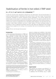
<strong>Mechanism</strong> <strong>of</strong> <strong>misorientation</strong> <strong>development</strong><br />
<strong>within</strong> <strong>coalesced</strong> martensite<br />
J. H. Pak 1 , H. K. D. H. Bhadeshia* 2 and L. Karlsson 3<br />
Coarse crystals <strong>of</strong> martensite can form by the coalescence <strong>of</strong> thin individual platelets <strong>of</strong><br />
martensite under appropriate circumstances. Although these coarse grains are essentially single<br />
crystals, there exist significant orientation gradients across their dimensions. It is demonstrated<br />
that these gradients arise because <strong>of</strong> the plasticity induced in austenite due to the transformation<br />
strain associated with martensite growth. The resulting localised change in austenite orientation is<br />
then inherited by the new martensite growth, which consumes the deformed austenite.<br />
Keywords: Martensite, Coalesced martensite, Orientation gradients, Shape deformation, Steels<br />
Introduction<br />
One <strong>of</strong> the attractive features <strong>of</strong> bainite or martensite is<br />
that the individual plates can be extremely thin, sometimes<br />
as thin as 20–40 nm in steels, which form bainite at<br />
temperatures ,200uC. 1–4 The thickness increases at<br />
higher transformation temperatures, typical <strong>of</strong> conventional<br />
alloys to ,0?2 mm in normal bainitic steels. 5–7<br />
A fine structure is conducive to a good combination <strong>of</strong><br />
strength and toughness, but it has been discovered that<br />
there are circumstances wherein adjacent platelets <strong>of</strong><br />
bainite that share the same habit plane and variant <strong>of</strong> the<br />
orientation relationship with austenite tend to impinge<br />
and coalesce in the absence <strong>of</strong> intervening phases. 8–12 The<br />
subject has been reviewed, 13 and a typical micrograph <strong>of</strong><br />
a coarse <strong>coalesced</strong> bainite plate is illustrated in Fig. 1;<br />
a three-dimensional characterisation using focused ion<br />
beam tomography has been reported. 14 It has been<br />
demonstrated that eliminating this coarsening process<br />
results in significantly improved toughness. 11–16<br />
As already stated, large plates, such as the one<br />
illustrated in Fig. 1, form as a consequence <strong>of</strong> the<br />
coalescence <strong>of</strong> finer platelets which are independently<br />
nucleated but share the same crystallography with the<br />
parent austenite. It has been shown, therefore, using<br />
electron back scatter diffraction, that large plates which<br />
are a consequence <strong>of</strong> coalescence are essentially single<br />
crystals but nevertheless contain orientation gradients <strong>of</strong><br />
y0?3u mm –1 . 17 Considering the common characteristics<br />
involved in bainite and martensite growth, 18 there is no<br />
reason to exclude the coalescence in martensitic structure<br />
once the large strain energy is available. The process<br />
has previously been described for isothermal martensite<br />
in an iron alloy. 19 In the present work, therefore, the<br />
coalescence in martensitic structure was explored and<br />
1 Graduate Institute <strong>of</strong> Ferrous Technology (GIFT), Pohang University <strong>of</strong><br />
Science and Technology (POSTECH), Pohang 790-784, Korea<br />
2 University <strong>of</strong> Cambridge Materials Science and Metallurgy, Cambridge<br />
CB2 3QZ, UK<br />
3 ESAB AB, Central Research Laboratories, Goteborg 40277, Sweden<br />
*Corresponding author, email hkdb@cam.ac.uk<br />
explained, especially focusing on the origin <strong>of</strong> the<br />
orientation gradients.<br />
Experimental<br />
The alloy used is a weld metal described elsewhere in<br />
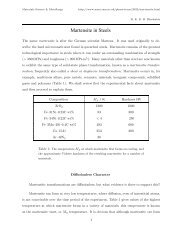
detail, 20 but the chemical composition is given in Table 1,<br />
chosen because <strong>of</strong> the propensity <strong>of</strong> this alloy to form<br />
<strong>coalesced</strong> bainite. Following austenitisation at 950uC for<br />
5 min, the sample was held at 385uC for 2000 s and then<br />
cooled continuously to obtain martensite.<br />
Transmission electron microscopy was carried out on<br />
a sample prepared specifically from a grain <strong>of</strong> <strong>coalesced</strong><br />
martensite using the focused ion beam technique, with<br />
the ion beam accelerating voltage reduced from 30 to<br />
5 kV for the final delicate milling.<br />
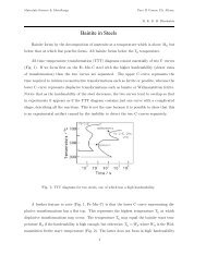
Dilatometry<br />
The whole dilatometry curve, including isothermal<br />
processes, is presented in Fig. 2a. The isothermal<br />
transformation was performed in the region indicated<br />
by the arrow (Fig. 2b). It is evident that the bainite<br />
hardly formed and the subsequent quenching induced<br />
almost fully martensitic transformation. The martensite<br />
start temperature was measured as 337¡2uC using the<br />
<strong>of</strong>fset method, 21 as shown in Fig. 3.<br />
Microscopy and diffraction<br />
The martensitic structure produced from the dilatometric<br />
experiments consists <strong>of</strong> fine platelets and abnormally<br />
large structures (Fig. 4a), where the latter correspond to<br />
the typical <strong>coalesced</strong> structures (Fig. 4b and c). 11 Figure 5<br />
shows a large plate <strong>of</strong> <strong>coalesced</strong> martensite in the region<br />
marked a, surrounded by ordinary fine plates <strong>of</strong><br />
martensite in the area designated b. Referring to the axes<br />
in Fig. 5, the plane <strong>of</strong> observation in the transmission<br />
electron microscope was x–z to ensure that the features<br />
observed correspond only to the <strong>coalesced</strong> structure. The<br />
transmission electron micrograph in Fig. 6 shows surprising<br />
detail, with evidence <strong>of</strong> the original platelets that<br />
integrated to form the <strong>coalesced</strong> plate in Fig. 5. The<br />
918<br />
ß 2012 Institute <strong>of</strong> Materials, Minerals and Mining<br />
Published by Maney on behalf <strong>of</strong> the Institute<br />
Received 18 January 2012; accepted 17 February 2012<br />
DOI 10.1179/1743284712Y.0000000023 Materials Science and Technology 2012 VOL 28 NO 8
Paketal.<br />
Misorientation <strong>development</strong> <strong>within</strong> <strong>coalesced</strong> martensite<br />
1 Coarse plate <strong>of</strong> <strong>coalesced</strong> bainite, many micrometres<br />
in thickness, forming by coalescence <strong>of</strong> finer platelets,<br />
which are visible towards right hand side 11<br />
boundaries between the platelets are visible, indicating<br />
that there may have been small <strong>misorientation</strong>s between<br />
the platelets before they <strong>coalesced</strong>.<br />
The electron diffraction patterns from ferrite platelets a,<br />
b and c, shown in Fig. 7, show that they are similarly<br />
oriented. However, the pattern from d could not be<br />
unambiguously indexed, so the sample was tilted to<br />
generate the pattern in Fig. 8; this indicated that the<br />
relationship between a and d could be described by a<br />
rotation <strong>of</strong> 9?4u about v110w a , which is crystallographically<br />
equivalent to 180u about [0?650 0?054 0?758] a ,where<br />
this axis is close to a diad, i.e. a small misorientaton. In<br />
other words, all the platelets a–d, which form the <strong>coalesced</strong><br />
plate, have small relative <strong>misorientation</strong>s.<br />
<strong>Mechanism</strong> for orientation gradients<br />
The shape deformation during the formation <strong>of</strong> bainite<br />
is an invariant plane strain with a large shear<br />
component, a shear strain <strong>of</strong> y0?26 on the habit<br />
plane. 22 A deformation like this is difficult to sustain<br />
elastically at the high temperatures where bainite forms,<br />
because the yield strength <strong>of</strong> austenite is low at elevated<br />
temperatures. Direct observations have shown that this<br />
accommodation occurs in a manner that compensates<br />
for the transformation shear. 22 Transmission microscopy<br />
<strong>of</strong> samples in which some austenite is preserved<br />
following the growth <strong>of</strong> bainite has at the same time<br />
shown that the plastic accommodation creates a large<br />
dislocation density in the austenite beside the bainite. 23<br />
Two things should be noticed: first, plastic accommodation<br />
can also happen even during martensite transformation<br />
when austenite fails to accommodate the<br />
deformation fully elastically; and second, systematic<br />
plasticity <strong>of</strong> this kind may change the effective crystallographic<br />
orientation in the deformed region. 24 In fact,<br />
Miyamoto et al. 25 revealed that austenite beside a<br />
platelet <strong>of</strong> martensite as well as bainite has curved<br />
planes due to this very effect.<br />
Therefore, a mechanism was proposed to induce small<br />
<strong>misorientation</strong>s between plates, which, in a perfect<br />
crystal <strong>of</strong> austenite, would be in exactly the same<br />
crystallographic disposition in space. Edge dislocations<br />
Table 1 Chemical composition <strong>of</strong> weld deposit studied<br />
(wt-%)<br />
C Si Mn P S Cr Ni Mo W<br />
0 . 03 0 . 23 2 . 05 0 . 01 0 . 008 0 . 43 7 . 1 0 . 63 0 . 004<br />
Co V Nb Cu Al Ti B O N<br />
0 . 008 0 . 021 0 . 004 0 . 02 0 . 001 0 . 011 0 . 0012 0 . 031 0 . 011<br />
present <strong>within</strong> the material only cause curvature <strong>of</strong> the<br />
lattice if there is an excess <strong>of</strong> positive or negative<br />
dislocations (extra half planes pointing above or below<br />
the slip plane respectively). Figure 9a illustrates the<br />
bending <strong>of</strong> glide planes caused by the presence <strong>of</strong> an<br />
excess density <strong>of</strong> edge dislocations with the same sign,<br />
the tilt being about an axis on the slip plane normal to<br />
the Burgers vector (<strong>of</strong> magnitude b). Suppose that the<br />
excess dislocation density localised into a region with<br />
width L (Fig. 9b); assuming a unit depth, the product rL<br />
gives the number <strong>of</strong> dislocations per unit length and its<br />
inverse the spacing between the dislocations in the array<br />
which that the tilt boundary. It follows that for small<br />
<strong>misorientation</strong>s, the <strong>misorientation</strong> h about the line<br />
vector is given by<br />
h~brL (1)<br />
The Burgers vector for slip in austenite is 1 = 2 a c v110w so<br />
that b52?548 Å for a lattice parameter <strong>of</strong> a c 53?604 Å.<br />
The dimension L representing the deformed austenite<br />
beside the bainite plate is taken to be equal to the typical<br />
width <strong>of</strong> the plate, 0?2 mm. Here, r is the dislocation<br />
density. Dislocations in martensite and bainite formed at<br />
high temperatures are inherited from the austenite<br />
deformed to be compatible to the transformation strain,<br />
so the dislocation density in the product should be the<br />
same as that in the parent. 26 The density r can therefore<br />
be estimated using an empirical equation available in the<br />
literature<br />
<br />
r<br />
<br />
log<br />
m {2 ^9:2848z 6880<br />
T { 1780360<br />
T 2<br />
for 570 KvTv920 K (2)<br />
where T is the absolute temperature at which the<br />
microstructure is generated. For martensite formed at<br />
337uC, r56?01610 15 m 22 .<br />
Considering that the growth <strong>of</strong> martensite is identical<br />
to that <strong>of</strong> bainite crystallographically and that the<br />
plastic accommodation is allowed in austenite, the habit<br />
plane <strong>of</strong> martensite is assumed to be that given by<br />
Davenport 27 as approximately (232) c , as illustrated in<br />
Fig. 9. Austenite slips on the system consisting <strong>of</strong> close<br />
packed planes and directions f111gv110w so that the<br />
slip direction approximately lies <strong>within</strong> the habit plane.<br />
Given that the habit plane is not a close packed plane<br />
<strong>of</strong> austenite, it requires a combination <strong>of</strong> slip systems<br />
to accommodate the transformation shear (we have<br />
neglected the smaller volume change due to transformation).<br />
Using the well established Taylor theory for the<br />
operation <strong>of</strong> multiple slip systems to account for an<br />
arbitrary plastic deformation, 28 it was found that the<br />
simultaneous operation <strong>of</strong> the slip systems (111)½101Š<br />
and (111)½101Š with the shear strain due to the former<br />
being five times that <strong>of</strong> the latter can accommodate the<br />
shape deformation <strong>of</strong> martensite. The full description<br />
for the calculation is available in Ref. 29.<br />
We now proceed to estimate the rotation <strong>of</strong> the<br />
austenite lattice caused by this multiple slip, assuming<br />
the model illustrated in Fig. 9. Equation (2) gives the<br />
total dislocation density rather than the excess density,<br />
which is not known and will be a fraction w <strong>of</strong> the total.<br />
Three values <strong>of</strong> the excess quantity were therefore tried,<br />
i.e. 0?25r, 0?5r and 0?75r, where r is the total<br />
dislocation density.<br />
Materials Science and Technology 2012 VOL 28 NO 8 919
Pak et al.<br />
Misorientation <strong>development</strong> <strong>within</strong> <strong>coalesced</strong> martensite<br />
2 Dilatometry curve for a whole temperature range and b isothermal transformation at 385uC<br />
3 Illustration to find start temperature <strong>of</strong> martensite transformation<br />
following isothermal process: dotted line corresponds<br />
to <strong>of</strong>fset line, and irregular curve indicated<br />
by arrow is due to unstable cooling in machine<br />
The rotation caused by multiple slip does depend on<br />
the order in which the slip systems operate, so four<br />
combinations <strong>of</strong> rotations were calculated, as listed in<br />
Table 2. The results show that the magnitudes <strong>of</strong> the<br />
rotations can be, as expected, small under appropriate<br />
excess density. It is interesting that the rotation axes<br />
listed are all approximately parallel to ½-11-1Š c<br />
, which<br />
corresponds to [101] a , given the orientation relationship<br />
between martensite and austenite. [101] a is <strong>of</strong> course the<br />
diad derived previously. Nevertheless, detailed comparison<br />
<strong>of</strong> the axis–angle pairs with observations is not<br />
possible because the specific crystallographic variants <strong>of</strong><br />
the habit planes and shape deformations <strong>of</strong> the structure<br />
illustrated in Fig. 6 cannot be determined from the thin<br />
foil studies. Note also that it is not possible to compare<br />
the axis–angle pairs derived using the earlier electron<br />
diffraction data because they do not include information<br />
about the axis <strong>of</strong> rotation.<br />
a overall microstructure; b observed <strong>coalesced</strong> structure; c reported <strong>coalesced</strong> bainite<br />
4 Observation using scanning electron microscopy 11<br />
920 Materials Science and Technology 2012 VOL 28 NO 8
Paketal.<br />
Misorientation <strong>development</strong> <strong>within</strong> <strong>coalesced</strong> martensite<br />
5 a <strong>coalesced</strong> and b fine martensite in focused ion beam<br />
micrograph: marked rectangle indicates area from<br />
which transmission electron microscopy sample was<br />
extracted<br />
6 Transmission electron micrograph montage representing<br />
<strong>coalesced</strong> martensite illustrated in Fig. 5<br />
7 Diffraction patterns from each platelet marked in Fig. 6: A, B and C are similarly oriented but pattern from d is ambiguous<br />
8 Diffraction patterns from platelets A and D marked in Fig. 6 after tilting relative to patterns shown in Fig. 7<br />
Materials Science and Technology 2012 VOL 28 NO 8 921
Pak et al.<br />
Misorientation <strong>development</strong> <strong>within</strong> <strong>coalesced</strong> martensite<br />
9 a dislocations causing <strong>development</strong> <strong>of</strong> <strong>misorientation</strong> in single crystal, b excess dislocations in grey area, assumed to<br />
align into column to cause constant <strong>misorientation</strong> between adjacent white areas and c plastic accommodation in austenite:<br />
region enclosed by dashed lines represents deformed austenite, upheaval being caused by shape deformation<br />
accompanying growth <strong>of</strong> martensite<br />
Table 2 Rotation axis and angle derived from operation slip systems a:(111)½101Š and b:(111)½101Š: R represents<br />
rotation operation with sequence <strong>of</strong> operation from right to left; all stated indices are with respect to austenite<br />
1<br />
w R b R a<br />
2 R 1<br />
b<br />
2 R 1<br />
a<br />
2 R 1<br />
b<br />
2 R a<br />
1<br />
2 R 1<br />
a<br />
2 R 1<br />
b<br />
2 R 1<br />
a<br />
2 R b R a R b<br />
0 . 25 3 . 48u 3 . 48u 3 . 48u 3 . 48u<br />
½0:5190:6860:510Š ½0:5170:6860:512Š ½0:5120:6860:517Š ½0:5100:6860:519Š<br />
0 . 50 6 . 96u 6 . 96u 6 . 96u 6 . 96u<br />
½0:5230:6860:505Š ½0:5190:6860:510Š ½0:5100:6860:519Š ½0:5050:6860:523Š<br />
0 . 75 10 . 44u 10 . 44u 10 . 44u 10 . 44u<br />
½0:5280:6860:501Š ½0:5210:6860:508Š ½0:5080:6860:521Š ½0:5010:6860:528Š<br />
922 Materials Science and Technology 2012 VOL 28 NO 8
Paketal.<br />
Misorientation <strong>development</strong> <strong>within</strong> <strong>coalesced</strong> martensite<br />
Conclusions<br />
It appears that the large plates which form by the<br />
coalescence <strong>of</strong> individual platelets <strong>of</strong> martensite retain<br />
vestiges <strong>of</strong> their origins because the boundaries <strong>of</strong> the<br />
original platelets are visible in transmission electron<br />
micrographs. This is because the platelets are not<br />
precisely identically oriented in space but have small<br />
relative rotations. These results are identical to those<br />
reported for the coalescence <strong>of</strong> bainite.<br />
The rotations are explained on the basis that the shape<br />
deformation accompanying the formation <strong>of</strong> a martensite<br />
plate causes plastic strain in the adjacent austenite.<br />
This in turn changes the crystallographic orientation <strong>of</strong><br />
the adjacent austenite, so that a new plate <strong>of</strong> martensite<br />
which grows from this deformed austenite will be<br />
slightly rotated relative to the original platelet.<br />
An estimate <strong>of</strong> the degree <strong>of</strong> resulting rotation gives<br />
reasonable numbers, although it has not been possible to<br />
attain a quantitative comparison with experimental<br />
observations because such observations are incomplete<br />
due to the fine scale <strong>of</strong> the structure and because <strong>of</strong> the<br />
absence <strong>of</strong> austenite. A complete closure with theory<br />
would require the three-dimensional crystallography<br />
(habit plane, shape deformation and orientation relationship)<br />
to be characterised.<br />
Acknowledgments<br />
The authors are grateful to the technical staff at the<br />
NCNT-POSTECH for help with the TEM and FIB<br />
work, and to J. H. Kang and J. H. Ryu for discussions.<br />
The present work was funded by the Steel Innovation<br />
Program <strong>of</strong> POSCO and the World Class University<br />
under programme no. R32-2008-000-10147-0 <strong>of</strong> the<br />
National Research Foundation <strong>of</strong> Korea.<br />
References<br />
1. C. Garcia-Mateo, F. G. Caballero and H. K. D. H. Bhadeshia:<br />
‘Development <strong>of</strong> hard bainite’, ISIJ Int., 2003, 43, 1238–1243.<br />
2. P. M. Brown and D. P. Baxter: ‘Hyper-strength bainitic steels’, in<br />
‘Materials science and technology’ , 433–438; 2004, Warrendale,<br />
PA, TMS.<br />
3. M. Kundu, S. Ganguly, S. Datta and P. P. Chattopadhyay:<br />
‘Simulating time temperature transformation diagrams <strong>of</strong> steels<br />
using artificial neural networks’, Mater. Manuf. Processes, 2009,<br />
24, 169–173.<br />
4. H. K. D. H. Bhadeshia: ‘Nanostructured bainite’, Proc. R. Soc.<br />
Lond. A, 2010, 466A, 3–18.<br />
5. F. B. Pickering: ‘<strong>Mechanism</strong> <strong>of</strong> bainite formation in low-alloy<br />
steels containing up to 0?4% carbon’, Proc. 4th Int. Conf. on<br />
‘Electron microscopy’, Berlin, Germany, September 1958,<br />
Springer-Verlag, 626–637.<br />
6. J. P. Naylor and P. R. Krahe: ‘The effect <strong>of</strong> bainite packet size on<br />
toughness’, Metall. Trans., 1974, 5, 1699–1701.<br />
7. L. C. Chang and H. K. D. H. Bhadeshia: ‘Microstructure <strong>of</strong> lower<br />
bainite formed at large undercoolings below the bainite start<br />
temperature’, Mater. Sci. Technol., 1996, 12, 233–236.<br />
8. R. Padmanabhan and W. E. Wood: ‘Occurrence <strong>of</strong> blocky<br />
martensite in 300M steel’, Mater. Sci. Eng., 1984, 66, 1–11.<br />
9. E. Keehan, H.-O. Andrén, L. Karlsson, M. Murugananth and<br />
H. K. D. H. Bhadeshia: ‘Microstructural and mechanical effects <strong>of</strong><br />
nickel and manganese on high strength steel weld metals’, in<br />
‘Trends in welding research’, (ed. S. A. David and T. DebRoy),<br />
695–700; 2002, Materials Park, OH, ASM.<br />
10. E. Keehan: ‘Microstructure and properties <strong>of</strong> novel high strength<br />
steel weld metals’, Weld. Res. Abroad, 2006, 52, 1–13.<br />
11. E. Keehan, L. Karlsson and H.-O. Andrén: ‘Influence <strong>of</strong> C, Mn<br />
and Ni on strong steel weld metals: Part 1, effect <strong>of</strong> nickel’, Sci.<br />
Technol. Weld. Join., 2006, 11, 1–8.<br />
12. L.-E. Svensson: ‘Microstructure and properties <strong>of</strong> high strength<br />
weld metals’, Mater. Sci. Forum, 2007, 539–543, 3937–3942.<br />
13. H. K. D. H. Bhadeshia, E. Keehan, L. Karlsson and H. O. Andrén:<br />
‘Coalesced bainite’, Trans. Indian Inst. Met., 2006, 59, 689–694.<br />
14. E. Keehan, L. Karlsson, H. K. D. H. Bhadeshia and M.<br />
Thuvander: ‘Three-dimensional analysis <strong>of</strong> <strong>coalesced</strong> bainite using<br />
focused ion beam tomography’, Mater. Charact., 2008, 59, 877–<br />
882.<br />
15. F. G. Caballero, J. Chao, J. Cornide, C. Garcia-Mateo, M. J.<br />
Sant<strong>of</strong>imia and C. Capdevila: ‘Toughness deterioration in<br />
advanced high strength bainitic steels’, Mater. Sci. Eng. A, 2009,<br />
A525, 87–95.<br />
16. F. G. Caballero, J. Chao, J. Cornide, C. Garcia-Mateo, M. J.<br />
Sant<strong>of</strong>imia and C. Capdevila: ‘Toughness <strong>of</strong> advanced high<br />
strength bainitic steels’, Mater. Sci. Forum, 2010, 638–642, 118–<br />
123.<br />
17. E. Keehan, L. Karlsson, H. K. D. H. Bhadeshia and M.<br />
Thuvander: ‘Electron backscattering diffraction study <strong>of</strong> <strong>coalesced</strong><br />
bainite in high strength steel weld metals’, Mater. Sci. Technol.,<br />
2008, 24, 1183–1188.<br />
18. H. K. D. H. Bhadeshia: ‘Design <strong>of</strong> ferritic creep-resistant steels’,<br />
ISIJ Int., 2001, 41, 621–640.<br />
19. D. Yang and M. Zhu: ‘Growth <strong>of</strong> isothermal martensite in an Fe–<br />
Ni–Mn alloy’, Acta Metall. Sin., 1988, 24, 236–241.<br />
20. J. H. Pak, H. K. D. H. Bhadeshia, L. Karlsson and E. Keehan:<br />
‘Coalesced bainite by isothermal transformation <strong>of</strong> reheated weld<br />
metal’, Sci. Technol. Weld. Join., 2008, 13, 593–597.<br />
21. H.-S. Yang and H. K. D. H. Bhadeshia: ‘Uncertainties in the<br />
dilatometric determination <strong>of</strong> the martensite-start temperature’,<br />
Mater. Sci. Technol., 2007, 23, 556–560.<br />
22. E. Swallow and H. K. D. H. Bhadeshia: ‘High resolution<br />
observations <strong>of</strong> displacements caused by bainitic transformation’,<br />
Mater. Sci. Technol., 1996, 12, 121–125.<br />
23. H. K. D. H. Bhadeshia and D. V. Edmonds: ‘The bainite<br />
transformation in a silicon steel’, Metall. Trans. A, 1979, 10A,<br />
895–907.<br />
24. J. W. Christian: ‘Simple geometry and crystallography applied to<br />
ferrous bainites’, Metall. Trans. A, 1990, 21A, 799–803.<br />
25. G. Miyamoto, A. Shibata, T. Maki and T. Furuhara: ‘Precise<br />
measurement <strong>of</strong> strain accommodation in austenite matrix<br />
surrounding martensite in ferrous alloys by electron backscatter<br />
diffraction analysis’, Acta Mater., 2009, 57, 1120–1131.<br />
26. J. W. Christian: ‘Thermodynamics and kinetics <strong>of</strong> martensite’,<br />
Proc. Int. Conf. on ‘Martensitic transformations’, (ed. G. B. Olson<br />
and M. Cohen), TMS, 220–234; 1979.<br />
27. A. T. Davenport: ‘The crystallography <strong>of</strong> upper bainite’, Technical<br />
report project no. 12051, Republic Steel Research Center,<br />
Independence, OH, USA, February 1974.<br />
28. D. N. Lee: ‘Texture and related phenomena’; 2006, Seoul, Korean<br />
Institute <strong>of</strong> Metals and Materials.<br />
29. J. H. Pak, D. W. Suh and H. K. D. H. Bhadeshia: ‘Bainite:<br />
fragmentation <strong>of</strong> crystallographically homogeneous domains’, Int.<br />
J. Mater. Res., 2012, 103, 1–7.<br />
Materials Science and Technology 2012 VOL 28 NO 8 923