
Create successful ePaper yourself
Turn your PDF publications into a flip-book with our unique Google optimized e-Paper software.
EDR4 1162 G2.16 10/03<br />
1
Important safety instructions for<br />
installation<br />
WARNING It is vital for the safety of persons to follow all instructions. Save<br />
these instructions.<br />
To prevent fire or shock hazard do not expose the opener to rain or moisture.<br />
To avoid electrical shock do not open the cabinet without disconnecting the opener from the mains.<br />
Incorrect installation can lead to severe injury. Follow all installation instructions.<br />
Garage doors are under great spring tension. Do not attempt to adjust spring tension. Do not<br />
loosen any brackets under spring tension. Do not remove springs from the door. Merlin does not<br />
accept responsibility for damage or injury resulting from installing this opener.<br />
To avoid difficulty during installation, do not connect the opener to the mains or run the door opener<br />
until instructed to do so.<br />
Do not use force sensitivity adjustments to compensate for a binding or sticking garage door.<br />
Excessive force may damage the garage door.<br />
Before installing the drive remove all unnecessary ropes or chains and disable any equipment, such<br />
as locks, that is not needed for powered operation.<br />
Before installing the drive check that the door is in good mechanical condition and that it is correctly<br />
balanced. Check that it opens and closes properly.<br />
Install the actuating member for the manual release (red handle on a rope) such that it rests at a<br />
height of less than 1.8m.<br />
Install any fixed control, wired or wireless, within sight of the door but away from moving parts and<br />
at a height of more than 1.5m.<br />
Install the drive such that all moving parts (except the door and the manual release) are at a height<br />
of more than 1.8m.<br />
Permanently attach the label warning against entrapment in a prominent place, or near any fixed<br />
control.<br />
Permanently fix the label concerning the manual release adjacent to its actuating member (thread<br />
the cord through the holes in the manual release warning card).<br />
After installation, ensure that the mechanism is properly adjusted and that the drive reverses when<br />
the door contacts a 40mm (50mm for UK) high object placed on the floor.<br />
The appliance is not intended for use by young children or infirm persons without supervision.<br />
If the supply cord is damaged, it must be replaced by the manufacturer or its service agent or a<br />
similarly qualified person in order to avoid a hazard.<br />
CE compliance after installation (EC countries only)<br />
It is the responsibility of the installer of the opener to ensure that the forces measured at the<br />
leading edge of the door are within the guidelines of BSEN 60335-2-95:2001. This may require<br />
adjustment of the drive and may also require adjustment of the door. Specialised measurement<br />
equipment may be required. Contact Merlin for assistance if necessary. If the measured forces<br />
exceed the guidelines then Merlin M102 non-contact sensors must be fitted.<br />
2<br />
EDR4 1162 G2.16 10/03
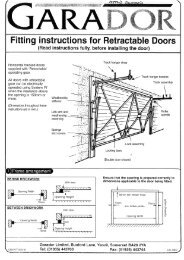
Site requirements<br />
Electrical Power Supply<br />
The opener is for 220-240 Volts AC - 50 Hz. There must be an earthed power point within 1.6<br />
metres of the mounting position.<br />
Garage Door<br />
This opener is designed for a residential roller door, maximum 3 metres high and 6 metres wide.<br />
Check that it is possible to raise the door by hand through the full height of the opening. The door<br />
should operate smoothly, rolling up and down level to the floor without the door curtain binding,<br />
bulging or coning. The door must not jam in the tracks. If in doubt consult Merlin.<br />
Clearances<br />
This opener has been designed to fit most existing roller doors. It can be mounted on the left or<br />
right hand sides of the garage.<br />
There must be at least 160mm between the edge of the door drum and the inside wall of the<br />
garage. If there is not then the opener will not fit at all.<br />
There must be at least 70mm between the inside wall of the garage and the free end of the door<br />
shaft.<br />
There must be at least 60mm between the edge of the door drum and the supporting wall bracket.<br />
There must be a drive spoke inside the drum closer than 130mm from the edge of the door drum.<br />
If there is not then contact Merlin for an adapter.<br />
Door Locks<br />
Existing door locks must be removed or disabled.<br />
The opener or the door can be damaged if you try<br />
to use it to open a locked door.<br />
MAX<br />
130<br />
MIN<br />
160<br />
Installation Height<br />
The opener must not be installed with its moving<br />
parts closer than 1.8m from the floor (2.5m for<br />
UK).<br />
MIN<br />
60<br />
MIN<br />
70<br />
Installation clearances<br />
for right hand mounting<br />
EDR4 1162 G2.16 10/03<br />
3
Preparing the opener<br />
WARNING Do not connect to the mains power or operate the opener until instructed<br />
to do so.<br />
STEP 1. Check the contents of the package.<br />
Your package should contain: this manual, a warranty sheet, black steel counter-weight bar, remote<br />
control transmitter, cast aluminium drive finger, two drive finger mounting bolts, nuts and spring<br />
washers, two screws with nuts for the weight bar, loosely bolted black plastic stop bracket assembly,<br />
red emergency release rope (with manual release warning card) and one assembled door<br />
opener.<br />
Contents of the package<br />
Drive finger<br />
& Bolts<br />
weight bar & Bolts<br />
transmitter, battery<br />
and clip<br />
stop bracket<br />
assembly<br />
manual release rope<br />
STEP 2. Fit the drive finger to the main drive gear.<br />
Ensure the rounded edge of the drive finger flange is in line with the curvature of the gear, that is<br />
rounded corners pointing towards the gear teeth.<br />
CAUTION Bolts must be inserted from the rear of the drive gear into the drive finger, or<br />
damage will be caused to the opener.<br />
Drive finger on main drive gear<br />
bolts through from<br />
rear of gear<br />
Outer pair<br />
of holes<br />
Inner pair of holes<br />
WARNING Roller doors are under great spring tension. It is important to secure<br />
the door curtain before loosening the brackets holding the door. Merlin does not<br />
accept responsibility for damage or injury resulting from installing this opener. Please read<br />
this manual fully before attempting installation.<br />
EDR4 1162 G2.16 10/03<br />
4
Preparing the roller door<br />
WARNING Do not loosen both door support brackets or clamps. Loosening both<br />
door shaft clamps will expose you to the risk of serious personal injury.<br />
STEP 1.<br />
Check that there is a power point available and that there is adequate clearance to mount the<br />
opener onto the door in your preferred location. Clearances are listed in the front of this manual.<br />
STEP 2.<br />
Roll the door up to the fully open position.<br />
STEP 3.<br />
Ensure that the U-bolt on the end of the door opposite the end to which the opener is to be fitted<br />
is tightened securely. This U-bolt holds all the spring tension on the door once the other U-bolt is<br />
released.<br />
STEP 4.<br />
Before loosening any bolts or clamps, mark the position of the main door-shaft on the wall bracket.<br />
This will allow the door to be re-installed with correct alignment after the opener is fitted.<br />
STEP 5.<br />
At the side of the door that the opener is to be fitted carefully loosen the door shaft U-clamp,<br />
checking that the spring tension inside the roller door drum is not being released.<br />
STEP 6.<br />
Remove the U-clamp from the<br />
bracket. Do not allow the drum to<br />
fall by sliding the shaft off the end<br />
of the bracket.<br />
Check this<br />
U-bolt is<br />
tight<br />
Mark the position of the<br />
shaft on the bracket.<br />
Remove<br />
the U-bolt<br />
EDR4 1162 G2.16 10/03<br />
Note: this assumes<br />
RH mounting has<br />
been chosen<br />
Preparing the roller door<br />
5
Installing the opener<br />
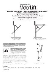
STEP 1.<br />
You will need assistance for this step. Slide or lift the door shaft clear of the wall bracket and slip<br />
the opener over the shaft. Turn the gear to engage the drive finger onto one of the support spokes<br />
inside the roller drum. Place the door shaft back onto the wall bracket in the position that it was<br />
originally. Refit and tighten the door shaft U-bolt.<br />
It may be necessary to remove the wall bracket. Mark the position before removing the bracket.<br />
5. Swing assembly back<br />
into position on bracket<br />
4. Engage drive<br />
fingers with spoke<br />
3. Slide opener<br />
onto shaft<br />
1. Support drum<br />
2. Slide drum<br />
away from bracket<br />
Installing the Opener<br />
If there is between 60mm and 160mm between the end of<br />
the door shaft and the side wall of the garage:<br />
It will be difficult to install the opener onto the door shaft. To make it easier, it is possible to split the<br />
drive gear and limit assembly from the motor and controller section. This will result in two smaller<br />
items that must then be re-attached after installing the drive section first.<br />
You will need to remove the limit switch cover, disconnect the limit wiring loom, undo two 8mm bolts<br />
and one 6mm screw. The two sections will now separate quite easily. Note the clutch stator is<br />
connected by a pin at the bottom right hand corner of the drive bracket.<br />
To reconnect take care to engage the clutch stator pin on the lower right hand corner of the drive<br />
bracket. Contact Merlin if you have any doubts about this.<br />
STEP 2.<br />
When the drive finger is engaged on a spoke, slide the opener along the door shaft until the large<br />
main gear is approximately 15mm clear of the edge of the door curtain. Tighten the two 8mm<br />
clamping bolts facing out of the bracket to secure the opener to the door shaft.<br />
EDR4 1162 G2.16 10/03<br />
6
15mm<br />
Tighten STEP 3.<br />
Re-check all mounting bolts to ensure door, opener<br />
and supporting wall brackets are all securely fastened.<br />
STEP 4.<br />
With the door in the open position fit the Stop<br />
Bracket onto the door shaft at the opposite end<br />
from the garage door opener. This bracket fits hard<br />
against the boss of the door drum spoke and helps<br />
prevent uneven rolling up of the door curtain after<br />
the opener is installed.<br />
Drive gear to drum clearance<br />
Opposite end<br />
to opener<br />
STEP 5.<br />
Fit the black steel weight-bar to the bottom centre<br />
of the door edge using the 5mm coach bolts<br />
and nuts supplied.<br />
STEP 6.<br />
Fit the release rope<br />
Tie the red release rope through the hole in the<br />
end of the release handle. Pull the red release rope<br />
to position the clutch lever in the down position.<br />
Ensure the release cord is threaded through the<br />
manual release warning card.<br />
Fit bracket against<br />
boss of drum spokes<br />
Stop Bracket Position<br />
EDR4 1162 G2.16 10/03<br />
Weight Bar Position<br />
Weight bar<br />
7
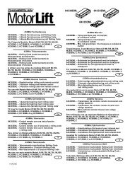
Setting the door travel limits<br />
Travel limit<br />
actuator<br />
arms<br />
Limit-switch<br />
cover panel<br />
Manual release<br />
Control panel<br />
cover<br />
Micro<br />
switches<br />
Fine adjusting<br />
screws<br />
The procedure for setting the door travel limits differs depending on which side of the garage door<br />
the opener has been fitted.<br />
STEP 1:<br />
Remove the black limit-switch cover panel<br />
from the right front face of the opener. (At<br />
the right of the smaller pinion gear.)<br />
Remove the green control panel cover from<br />
the left front face of the opener.<br />
STEP 2:<br />
As viewed while looking out of the garage<br />
through the doorway, is the opener on the<br />
right-hand or left-hand side?<br />
remove<br />
for setup<br />
exit delay<br />
Light door<br />
roller: L<br />
tall door<br />
autoclose<br />
open<br />
open<br />
force<br />
on<br />
on<br />
R<br />
on<br />
short<br />
long<br />
auto<br />
operate<br />
learn<br />
delete<br />
program<br />
auto<br />
manual<br />
control<br />
close<br />
force<br />
close<br />
EDR4 1162 G2.16 10/03<br />
8
Setting door travel limits for right-hand mounting only<br />
STEP 1:<br />
Inspect the option switches on the control panel. The switch marked ‘Roller L:R’ should be moved to<br />
the R position.<br />
STEP 2: Set the bottom limit of travel.<br />
Connect the mains power to the opener and switch the power on. Pull the manual release to<br />
disengage the door from the opener. Lower the door manually to the fully closed position.<br />
Observe the red LED on the control panel. It should be flashing. (If the red LED is on continuously,<br />
rotate the front actuator arm clockwise. If the green LED is on continuously, rotate the rear actuator<br />
arm anti-clockwise.)<br />
Rotate the front limit-actuator-arm anti-clockwise until it contacts its microswitch and the red LED<br />
stays on continuously.<br />
STEP 3: Set the upper limit of travel.<br />
Raise the door manually to the fully open position.<br />
Observe the green LED on the control panel. It should be flashing. (If it isn’t then rotate the rear<br />
limit-actuator-arm anti-clockwise away from its microswitch.)<br />
Rotate the rear limit-actuator-arm clockwise until it contacts its microswitch and the green LED<br />
stays on continuously.<br />
Setting door travel limits for left-hand mounting only<br />
STEP 1:<br />
Inspect the option switches on the control panel. The switch marked ‘Roller L:R’ should be moved to<br />
the L position.<br />
STEP 2: Set the bottom limit of travel.<br />
Connect the mains power to the opener and switch the power on. Pull the manual release to<br />
disengage the door from the opener. Lower the door manually to the fully closed position.<br />
Observe the red LED on the control panel. It should be flashing. (If the red LED is on continuously,<br />
rotate the front actuator arm clockwise. If the green LED is on continuously, rotate the rear actuator<br />
arm anti-clockwise.)<br />
Rotate the rear limit-actuator-arm clockwise until it contacts its microswitch and the red LED stays<br />
on continuously.<br />
EDR4 1162 G2.16 10/03<br />
STEP 3: Set the upper limit of travel.<br />
Raise the door manually to the fully open position.<br />
Observe the green LED on the control panel. It should be flashing. (If it isn’t then rotate the rear<br />
limit-actuator-arm anti-clockwise away from its microswitch.)<br />
Rotate the front limit-actuator-arm anti-clockwise until it contacts its microswitch and the green<br />
LED stays on continuously.<br />
The limits are now largely set in the correct position. However the door travel can be further adjusted<br />
using the fine adjustment screws.<br />
Each turn of the screw results in around 5mm of door travel.<br />
9
WARNING: The door is not safe for unsupervised operation until the force sensitivity<br />
has been set.<br />
NOTE Repeated operation of the opener in a short period of time during the setting of force<br />
sensitivity may trigger the thermal cutout of the motor. In this case you will have to wait for<br />
approximately five minutes for the motor to cool sufficiently to continue the installation<br />
process. If the unit has overheated you will hear the relays clicking in response to the<br />
transmitter or pushbutton but the motor will not operate. After cooling down, normal operation<br />
is able to resume.<br />
Improving the door security<br />
In most cases the opener acts as a lock on the door. However some doors allow the curtain to slide<br />
up in the tracks even when the drum is held stationary by the opener. In these cases we recommend<br />
the addition of bolts or pop-rivets to hold the curtain against the drum:<br />
STEP 1.<br />
Pull the red rope to disengage the clutch. Close the door manually. Push the clutch lever (attached<br />
to the red rope) up.<br />
STEP 2.<br />
Try to manually open the door with the opener engaged. (There will be a clunk as the opener<br />
engages its clutch.) Any excess door curtain may billow out from the top of the drum.<br />
Free curtain<br />
Billowing<br />
Add fasteners here<br />
Door closed Door can be lifted Door secure<br />
Securing door curtain to drum<br />
STEP 3.<br />
To remedy any billowing place gutter-bolts or pop rivets (not supplied) 75mm up from where the<br />
curtain leaves the roll. Secure these through the curtain into the spokes.<br />
EDR4 1162 G2.16 10/03<br />
10
Setting the force sensitivity<br />
The force sensing is not preset and must be set correctly to suit your door.<br />
STEP 1:<br />
Remove the green control panel cover from the left front face of the opener.<br />
STEP 2:<br />
Identify the green and the red control knobs marked open-force and close-force.<br />
Note: The opener can be set to either determine its own safe operating force level, or it can be set<br />
to allow a deliberately greater amount of force to be applied to the door.<br />
STEP 3:<br />
To set the force levels automatically, press the program button and turn the control knobs fully<br />
anticlockwise. Ensure that the door is engaged to the opener. Then operate the opener to move the<br />
door in a single unobstructed movement from one limit position to the other. If no obstruction was<br />
sensed during this cycle then the opener will save the settings to memory. Operate the opener to<br />
move the door back to the original limit position. Again, if no obstruction is sensed, the settings will<br />
be stored in memory.<br />
EDR4 1162 G2.16 10/03<br />
STEP 4:<br />
To set the force levels at some higher level, rotate the control knob to some position clockwise from<br />
the auto-setting point.<br />
STEP 5:<br />
If a very light door is being operated, and if a very gentle closing force is required, then set the<br />
option switch marked ‘Light door’ to the ON position. Note that on a heavier door this option switch<br />
position may result in unintended detections of obstructions.<br />
NOTE: To reset the adaptive and automatic force settings at any time, press the program button<br />
once.<br />
Setting up wireless controls<br />
Wireless controls can operate the opener, or the opener’s courtesy lamp, by sending coded radio<br />
signals. These coded signals use high-security code-hopping.<br />
Wireless controls can be hand-held or fixed to walls, such as a wireless keypad, or a wireless wallswitch.<br />
Up to 20 Merlin wireless controls can be learned by the opener. After this, the 20th wireless control<br />
is over-written in the opener’s memory.<br />
All wireless controls can be deleted from the opener’s memory.<br />
There is a red learn button under the red control panel cover on the front face of the opener. The<br />
small button on a Merlin M-122 wired wall-switch can also be used as the learn button.<br />
If a setting is enabled in the opener, then it is possible to use any existing learned wireless control<br />
as a learn button. (See separate section following.)<br />
11
To learn a remote button to operate the opener:<br />
Press the learn button for 1-2 seconds, until the courtesy lamp begins to flash slowly.<br />
Press the desired remote button, wait 1 second, press the desired remote button again. The courtesy<br />
lamp will stop flashing once learning is complete.<br />
To learn one remote button to operate the opener and another to operate the lamp:<br />
Press the learn button for 1-2 seconds, until the courtesy lamp begins to flash slowly.<br />
Press the desired remote button for control of the opener, wait 1 second, press the desired remote<br />
button for control of the courtesy lamp. The courtesy lamp will stop flashing once learning is complete.<br />
To delete all remote controls from the opener’s memory<br />
Press and hold the learn button for eleven seconds, until the courtesy lamp stops flashing. After six<br />
seconds it will flash fast as a warning. If you release the learn button during this warning period<br />
then the memory will not be wiped.<br />
Remote transmitter learning<br />
Remote Transmitter Learning (RTL), when enabled, allows any existing learned wireless control to<br />
be used as a learn button for the learning of additional wireless controls. Note that this feature<br />
trades convenience for security. If it is chosen to disable RTL (the default setting at manufacture is<br />
enabled) then the level of security is increased.<br />
To enable or disable RTL:<br />
Remove the green control panel cover to expose the setup controls. Identify the red learn button<br />
and the black program button.<br />
Hold both of the these buttons down for three seconds until the courtesy lamp begins to flash.<br />
Release both buttons.<br />
Six flashes confirms that RTL is now enabled.<br />
Four flashes confirms that RTL is now disabled.<br />
To place the opener in learn mode using RTL:<br />
Select any two or four button Merlin hand held remote control that is already learned in to the<br />
opener. Call this the master remote.<br />
Press the master remote's north and south buttons together for 2-3 seconds.<br />
The courtesy lamp on the opener will begin to repeat a cycle of flashing three times and pausing. If<br />
you have several openers that operate from this master remote, then all these openers will begin to<br />
flash their courtesy lamps.<br />
Press the button on the master remote that would normally operate the desired opener. Now that<br />
opener will go into learn mode, and any other openers that were flashing will return to their normal<br />
standby state.<br />
The courtesy lamp on the opener that is in learn mode will begin to flash slowly. You have 20<br />
seconds to complete the next step. If no signals are received for 20 seconds, the opener will revert<br />
to its normal standby state.<br />
EDR4 1162 G2.16 10/03<br />
12
To learn a button to operate the opener:<br />
Press the desired remote button, wait 1 second, press the desired remote button again. The courtesy<br />
lamp will stop flashing once learning is complete.<br />
To learn one remote button to operate the opener and another to operate the lamp:<br />
Press the learn button for 1-2 seconds, until the courtesy lamp begins to flash slowly.<br />
Press the desired remote button for control of the opener, wait 1 second, press the desired remote<br />
button for control of the courtesy lamp. The courtesy lamp will stop flashing once learning is complete.<br />
Enabling auto-closing<br />
(Optional in NZ/Aus only)<br />
CAUTION Additional safety features may over-ride the auto-closure feature.<br />
Auto-close cannot be guaranteed to always occur.<br />
Always maintain visual contact with a closing door.<br />
This opener requires the Merlin M102 non-contact beam sensor to be fitted before the auto-close<br />
feature will operate. If the beam is interrupted the door will not close unless the manual pushbutton<br />
is held for more than two seconds.<br />
There is no guarantee given by Merlin that the beam will always protect property and persons from<br />
accidental injury or damage from unsupervised operation of the opener.<br />
To enable the option, remove the green control panel. Find the option setting switch.<br />
For a 30 second delay: autoclose short ON<br />
For a 60 second delay: autoclose long ON<br />
For a 90 second delay: both short + long ON<br />
EDR4 1162 G2.16 10/03<br />
13
Adding the Merlin M102 beam<br />
sensor (Optional)<br />
Non-contact Near-Infra-Red beam sensors are optional but may be required in EC countries.<br />
Merlin strongly suggests they be fitted for increased levels of safety.<br />
If sensors are fitted the opener will only close when the sensors are fully functional and where their<br />
beam is unobstructed.<br />
The sensors should be placed either side of the door opening, within 300-mm of the door’s opening,<br />
and within 100-mm of the floor. Choose positions that will protect the sensors from accidental<br />
impact or water. If one sensor is marked ‘receiver’ then do not place that sensor where it will be<br />
subjected to bright direct sunlight. The high level of Infra Red light in bright sunlight may temporarily<br />
prevent normal operation of the opener.<br />
Switch off the power to the opener. Run the pair of cables from each sensor back to the accessory<br />
terminals on the rear of the opener.<br />
There is no need to connect the cables with any particular Non contact beam sensor<br />
polarity.<br />
The door can open regardless of the sensor beam. Only<br />
the closing operation is affected by the state of the beam.<br />
If the beam is obstructed, or if the sensors are not functioning,<br />
then the door may still be closed by holding the<br />
manual control button down for at least two seconds, and<br />
keeping it held until the door is closed.<br />
NIR Light beam<br />
Max 7 metres<br />
Connecting the wall control box<br />
(Optional)<br />
The M-122 wall control box can be wired<br />
to the accessory terminal strip.<br />
This will allow the user to control the<br />
opener and lamp by fixed wiring.<br />
Connect to the accessory terminals<br />
marked 'manual control' under the<br />
opener, inside the lamp cover, under a<br />
panel.<br />
EDR4 1162 G2.16 10/03<br />
14
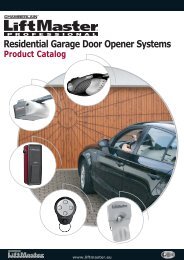
420<br />
220<br />
51<br />
Specifications<br />
Replacement light bulb E27 45mm Round, 40W maximum, RC preferred<br />
Mains power required<br />
220V to 240 V, 50 Hz, single phase AC, earthed<br />
Suitable for<br />
domestic roller doors only. Not rated for shutter doors<br />
Curtain edge speed<br />
dependent on drum size - approximately 7-10 seconds per drum<br />
revolution<br />
Maximum rated torque 70Nm<br />
Maximum door height<br />
dependent on drum size - approximately 3 metres (3 drum rotations)<br />
Minimum door height UK 2.5m, Aus/NZ 1.8m<br />
Stand-by power consumption 3W maximum<br />
Operating power consumption 900W maximum<br />
Ambient operating temperature +5 0 C to +40 0 C<br />
135<br />
270<br />
160<br />
142<br />
58<br />
25<br />
Overall dimensions<br />
166<br />
EDR4 1162 G2.16 10/03<br />
15
Merlin service centres<br />
New Zealand<br />
Auckland phone 09 415 4393<br />
Phone toll free 0800 653 667 or 0800 MERLIN<br />
Fax toll free 0800 653 663<br />
Australia<br />
NSW, Vic, Qld, WA<br />
Phone toll free 1 800 638 243<br />
Fax toll free 1 800 640 243<br />
England<br />
Phone toll free 0800 073 0112<br />
Fax toll free 01709 514 534<br />
www.merlingo.com<br />
Merlin does not accept responsibility for damage or injury resulting from installing this opener.<br />
Merlin reserves the right to change the design and specification without prior notification. Some<br />
features or accessories may not be available in certain markets or areas. Please check with your<br />
distributor.<br />
16<br />
27<br />
EDR4 1162 G2.16 10/03