CNC2 Communications Node Controller Data Sheet - Trend
CNC2 Communications Node Controller Data Sheet - Trend CNC2 Communications Node Controller Data Sheet - Trend
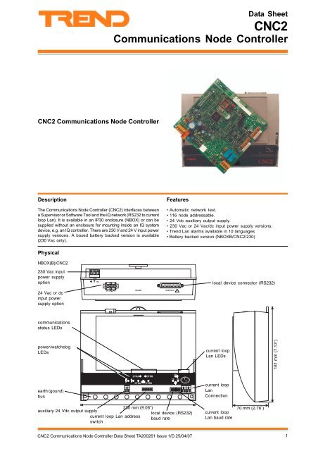
Data Sheet CNC2 Communications Node Controller CNC2 Communications Node Controller Description The Communications Node Controller (CNC2) interfaces between a Supervisor or Software Tool and the IQ network (RS232 to current loop Lan). It is available in an IP30 enclosure (NBOX) or can be supplied without an enclosure for mounting inside an IQ system device, e.g. an IQ controller. There are 230 V and 24 V input power supply versions. A boxed battery backed version is available (230 Vac only). Features • Automatic network test. • 116 node addressable. • 24 Vdc auxiliary output supply. • 230 Vac or 24 Vac/dc input power supply versions. • Trend Lan alarms available in 10 languages • Battery backed version (NBOXB/CNC2/230) Physical NBOX(B)/CNC2 230 Vac input power supply option ! 8 local device connector (RS232) 24 Vac or dc input power supply option " 8 , - 4 , 5 4 5 ! communications status LEDs power/watchdog LEDs current loop Lan LEDs 181 mm (7.13”) , 6 4 ) , 6 4 * 6 : 4 : earth (gound) bus + 6 5 ) + 6 5 * current loop Lan Connection 230 mm (9.06”) 70 mm (2.76”) auxiliary 24 Vdc output supply local device (RS232) current loop current loop Lan address baud rate Lan baud rate switch CNC2 Communications Node Controller Data Sheet TA200261 Issue 1/D 25/04/07 1
- Page 2 and 3: FUNCTIONALITY The CNC2 interfaces b
- Page 4 and 5: CNC2 Data Sheet INSTALLATION If the
- Page 6 and 7: CNC2 Data Sheet CONNECTIONS Board C
- Page 8: CNC2 Data Sheet SPECIFICATIONS Elec
<strong>Data</strong> <strong>Sheet</strong><br />
<strong>CNC2</strong><br />
<strong>Communications</strong> <strong>Node</strong> <strong>Controller</strong><br />
<strong>CNC2</strong> <strong>Communications</strong> <strong>Node</strong> <strong>Controller</strong><br />
Description<br />
The <strong>Communications</strong> <strong>Node</strong> <strong>Controller</strong> (<strong>CNC2</strong>) interfaces between<br />
a Supervisor or Software Tool and the IQ network (RS232 to current<br />
loop Lan). It is available in an IP30 enclosure (NBOX) or can be<br />
supplied without an enclosure for mounting inside an IQ system<br />
device, e.g. an IQ controller. There are 230 V and 24 V input power<br />
supply versions. A boxed battery backed version is available<br />
(230 Vac only).<br />
Features<br />
• Automatic network test.<br />
• 116 node addressable.<br />
• 24 Vdc auxiliary output supply.<br />
• 230 Vac or 24 Vac/dc input power supply versions.<br />
• <strong>Trend</strong> Lan alarms available in 10 languages<br />
• Battery backed version (NBOXB/<strong>CNC2</strong>/230)<br />
Physical<br />
NBOX(B)/<strong>CNC2</strong><br />
230 Vac input<br />
power supply<br />
option<br />
! 8<br />
<br />
local device connector (RS232)<br />
24 Vac or dc<br />
input power<br />
supply option<br />
" 8<br />
<br />
, - <br />
4 , 5 4 5 ! <br />
communications<br />
status LEDs<br />
power/watchdog<br />
LEDs<br />
current loop<br />
Lan LEDs<br />
181 mm (7.13”)<br />
, 6 4 )<br />
, 6 4 *<br />
<br />
6 : 4 :<br />
earth (gound)<br />
bus<br />
+ 6 5 )<br />
+ 6 5 *<br />
current loop<br />
Lan<br />
Connection<br />
230 mm (9.06”) 70 mm (2.76”)<br />
auxiliary 24 Vdc output supply<br />
local device (RS232) current loop<br />
current loop Lan address<br />
baud rate<br />
Lan baud rate<br />
switch<br />
<strong>CNC2</strong> <strong>Communications</strong> <strong>Node</strong> <strong>Controller</strong> <strong>Data</strong> <strong>Sheet</strong> TA200261 Issue 1/D 25/04/07<br />
1
FUNCTIONALITY<br />
The <strong>CNC2</strong> interfaces between a local device connected by way<br />
of the RS232 port (e.g. an NDP, or a PC running a <strong>Trend</strong> Supervisor<br />
or Software Tool) and the current loop Lan; it also provides<br />
certain network maintenance operations. The <strong>CNC2</strong> continually<br />
monitors the Lan, if it receives data that is addressed to a<br />
different node it passes it on around the Lan through its transmit<br />
port. If it receives data for its own address, it will transmit it to<br />
the RS232 port. When data arrives from the RS232 port, it<br />
transmits the data onto the Lan through the transmit port.<br />
receive port<br />
<strong>CNC2</strong><br />
Local device<br />
(e.g. Supervisor)<br />
RS232 port<br />
transmit port<br />
The <strong>CNC2</strong> also monitors Lan integrity by performing continuous<br />
checking of network messages. Alarm messages are generated<br />
whenever a problem occurs.<br />
IQ<br />
Current<br />
loop Lan<br />
<strong>CNC2</strong><br />
RS232<br />
NDP<br />
IQ<br />
HARDWARE<br />
Packaging: The <strong>CNC2</strong> can be provided boxed, or as a board<br />
version.<br />
Boxed version: The <strong>CNC2</strong> can be supplied in a plastic<br />
enclosure with a transparent plastic flip-up terminal<br />
cover (NBOX/<strong>CNC2</strong>/...). It has 3 point mounting to facilitate<br />
installation. There is an optional battery backup to keep<br />
the node functioning in the event of input power supply<br />
failure (NBOXB/<strong>CNC2</strong>/230- 230 Vac version only). An<br />
optional metal enclosure with cable gland knockouts is<br />
available (ENCLS/MBOX/IQ22x).<br />
Fusing: No replaceable fuses are fitted. Protection is proved by<br />
a self-resetting thermally protected transformer. The 24 V version<br />
is protected by a self-resetting PTC device.<br />
Auxiliary Output supply: Then <strong>CNC2</strong> can supply 24 Vdc ±10<br />
% at 150 mA maximum to a peripheral device (e.g. NDP).<br />
RS232/Lan connections: The local device connection is referred<br />
to as the RS232 port on the NBOX version, and as the Device B<br />
connection on the board version. The IQ current loop Lan is<br />
referred to as Lan A.<br />
Board version: The board version will fit inside certain<br />
IQ controllers. The controllers can be ordered pre-fitted<br />
with the node (e.g. IQ241/<strong>CNC2</strong>/...), or the node can be<br />
retrofitted by using the appropriate fitting kit<br />
(KIT/NODE/IQ23x for IQ231/233, KIT/NODE/IQ24x for<br />
IQ241/242, or KIT/NODE/IQ25x for IQ250/251).<br />
Network : The two part network terminals are for 2 wire<br />
cables. The standard IQ system node features are identified<br />
(Lan OK, TX, RX indicators, bypass relay, network alarm<br />
generation).<br />
RS232 port<br />
(NBOX)<br />
<strong>CNC2</strong><br />
Lan<br />
(Lan A)<br />
local device<br />
RS232<br />
Dev B, modem (J16)<br />
(board)<br />
Address Switch : The <strong>CNC2</strong> device address on the local<br />
Lan is selected by address switch poles 1 to 7. It may be set in<br />
the range 1, 4 to 9, 11 to 119 and must be unique on the local Lan.<br />
Dumb/Normal Switch: The dumb/normal switch setting<br />
(SW1, pole 8) is ignored by the <strong>CNC2</strong>.<br />
Baud Rate Links : The local Lan and local device (RS232)<br />
baud rates are set by two sets of links to 19k2, 9k6, 4k8, or 1k2.<br />
The local Lan baud rate must be set to match other nodes on the<br />
local Lan. The local device (RS232) baud rate must match the<br />
local device.<br />
The local Lan (Lan A) connection is duplicated on the <strong>CNC2</strong> board<br />
as the Device A RS232 connection (J15). If an RS232 device<br />
were to be connected to the RS232 connector (Dev A), the Lan<br />
connection (Lan A) would be effectively disconnected.<br />
Battery Backup: NBOXB/<strong>CNC2</strong>/230 (230 Vac version only).<br />
Rechargeable batteries maintain node operations for 20 minutes<br />
(typical) during input power supply failure. The battery circuit is<br />
enabled by two links (J12, J13), and by default the battery circuit<br />
is disabled (OFF). The battery links should be moved to the ON<br />
position after power up to enable the battery backup. The unit<br />
should be powered on for at least 16 hours after moving the links<br />
to the ON position to charge up the batteries.<br />
Network bypass relay : In order that the network continues<br />
to operate if the <strong>CNC2</strong> fails, a node bypass relay is fitted to<br />
maintain network integrity in the event failure of the node’s input<br />
power supply, of failure of the node itself. The bypassing of a<br />
node will be recognised by the downstream node, and reported<br />
as a Lan Changed alarm.<br />
Input Power Supply: The battery backed boxed <strong>CNC2</strong><br />
(NBOXB/<strong>CNC2</strong>/230) can only be supplied in 230 Vac version but<br />
the boxed version without the battery backup (NBOX/<strong>CNC2</strong>/...)<br />
can be supplied in 230 Vac and 24 V(ac or dc) versions. The 230<br />
Vac version is supplied with an optional input power supply<br />
terminal shroud.<br />
The board version requires 24 Vdc, or 18 Vac (transformer<br />
isolated), or 18-0-18 Vac (transformer centre tapped).
HARDWARE (continued)<br />
Indicators: The <strong>CNC2</strong> has 9 indicators to monitor unit status.<br />
(Power)<br />
(Watchdog)<br />
DTRA<br />
(green) On when input power supply is on<br />
(normally ON); if OFF, power fail.<br />
(red) On if a processor or software fault<br />
(normally OFF); if ON, <strong>CNC2</strong> fail.<br />
(yellow) <strong>CNC2</strong> busy to local Lan (Lan A) (normally<br />
flashes).<br />
CTSA (yellow) not used.<br />
DTRB (yellow) <strong>CNC2</strong> busy to local device (RS232 port<br />
or Dev B). (normally flashes).<br />
CTSB (yellow) Local device (RS232 port or Dev B)<br />
busy to <strong>CNC2</strong>.<br />
TX<br />
(yellow) Monitors current flow from <strong>CNC2</strong> to<br />
current loop Lan (Lan A). (normally ON). If OFF,<br />
transmit connection to next node may be broken.<br />
RX<br />
(yellow) Monitors current flow to <strong>CNC2</strong> from<br />
current loop Lan (Lan A). (normally ON). If OFF,<br />
receive connection from previous node may be<br />
broken or short-circuited.<br />
OK<br />
(green) ON if local Lan (Lan A) OK. Flashes if<br />
prohibited Lan address (0, 2, 3, >119) set on<br />
address switch. OFF if Lan fault (e.g. baud rate<br />
conflict).<br />
Connectors: Two part connectors are used throughout to<br />
facilitate wiring. A busbar is provided for screen termination<br />
(NBOX(B) only).<br />
FIRMWARE<br />
Alarms: The <strong>CNC2</strong> also helps to maintain a high level of network<br />
integrity by performing continuous checking of network<br />
messages. The following alarms are generated when faults are<br />
found:<br />
“Remote LAN From <strong>CNC2</strong> on Lan xx -<br />
Lan Broken NKBK” - a break in communications over the<br />
local Lan.<br />
Lan OK NKOK” - local Lan communications are restored.<br />
Lan Changed NKCH” - a node has gone from or been added<br />
to the local Lan.<br />
Duplicate address NKDA” - the <strong>CNC2</strong>’s address is<br />
duplicated on the local lan.<br />
It will deliver these alarms to the RS232 port local device in the<br />
format required by the supervisor (text or critical).<br />
Device Ok DVOK” - <strong>CNC2</strong> has detected that the local device<br />
is connected and active.<br />
Device Dead DVDD”- <strong>CNC2</strong> has detected that the local<br />
device is either disconnected or is inactive.<br />
These alarms are transmitted on the local Lan. Any other<br />
supervisor connected to the local Lan will receive these alarms.<br />
Identification: The <strong>CNC2</strong> will reply to a request for details sent<br />
to address 10 from the supervisor or software tool running in<br />
the PC connected by way of RS232.<br />
If the local device is dead, the <strong>CNC2</strong> identifies itself to ‘w’ Comms<br />
as <strong>CNC2</strong> v5.xx.<br />
Alarm Language: Some <strong>Trend</strong> Supervisors or software tools<br />
are able to set the <strong>CNC2</strong> to report its network alarms in foreign<br />
languages (English, Spanish, Finnish, Swedish, Norwegian,<br />
Danish, German, Italian, Portuguese, French).
<strong>CNC2</strong><br />
<strong>Data</strong> <strong>Sheet</strong><br />
INSTALLATION<br />
If the <strong>CNC2</strong> is supplied as a board, it must first be mounted in a suitable enclosure (e.g. certain IQ controllers, NBOX). It is normally<br />
mounted on 4 pillars. The NBOX(B)/<strong>CNC2</strong> must be mounted on a flat surface by way of 3 off 6 mm (0.24”) holes using screws/rawl<br />
plugs. The <strong>CNC2</strong> installation involves the following procedure:<br />
Mount the unit in position<br />
Route cables<br />
Connect the network<br />
Set network address<br />
Set network baud rate<br />
Connect input power supply<br />
Connect to device<br />
Connect Auxiliary Output Supply (if used)<br />
Test<br />
A full description of installing the NBOX(B)/<strong>CNC2</strong> is provided in the NBOX(B)/<strong>CNC2</strong> Installation Instructions, TG200265. Instructions<br />
for installing a <strong>CNC2</strong> board only are provided in the <strong>CNC2</strong> Installation Instructions, TG200262.<br />
The installation of an NBOX(B)/<strong>CNC2</strong> using an ENCLS/MBOX/IQ22x is covered by ENCLS/MBOX/IQ22x Installation Instructions<br />
TG200204.<br />
4 <strong>CNC2</strong> <strong>Communications</strong> <strong>Node</strong> <strong>Controller</strong> <strong>Data</strong> <strong>Sheet</strong> TA200261 Issue 1/D 25/04/07
<strong>Data</strong> <strong>Sheet</strong><br />
<strong>CNC2</strong><br />
CONNECTIONS<br />
Boxed<br />
NBOX(B)/<strong>CNC2</strong><br />
230 Vac Input Power<br />
Supply (option)<br />
2 part<br />
E N L 230 Vac<br />
~<br />
E N L<br />
24 V (ac or dc) Input Power<br />
Supply (option)<br />
Mat-N-Loc to<br />
terminal<br />
adaptor<br />
(supplied)<br />
24 Vdc: +24V 0V<br />
24 Vac: 24 Vac 0V<br />
EJ105383<br />
24V<br />
Earth (ground)<br />
! 8<br />
<br />
" 8<br />
<br />
, - <br />
4 , 5 4 5 ! <br />
<strong>CNC2</strong> to local device connection<br />
(RS232 port)<br />
(24 Way, D type, Female)<br />
cable not supplied<br />
with unit<br />
25 Way, D type, Male<br />
local device<br />
(PC or NDP)<br />
CABLE/58-0750<br />
, 6 4 )<br />
, 6 4 *<br />
<br />
6 : 4 :<br />
+ 6 5 )<br />
+ 6 5 *<br />
9 Way, D type, Female<br />
Auxiliary Output<br />
Supply (24 Vdc)<br />
IQ Current Loop Lan (Lan A)<br />
polarity independent<br />
AUX<br />
24 V<br />
2 wire<br />
) )<br />
Earth (ground) Bus<br />
4<br />
4<br />
6 <br />
6 4 4 <br />
A = HJD > K I<br />
:<br />
6<br />
6<br />
24 Vdc (150 mA max)<br />
Connect bus to earth<br />
(ground) separately<br />
4 wire<br />
4<br />
4<br />
6<br />
6<br />
A = HJD > K I<br />
) )<br />
6 6 4 4 <br />
:<br />
additional<br />
terminals<br />
6<br />
6<br />
4<br />
4<br />
<strong>CNC2</strong> <strong>Communications</strong> <strong>Node</strong> <strong>Controller</strong> <strong>Data</strong> <strong>Sheet</strong> TA200261 Issue 1/D 25/04/07<br />
5
<strong>CNC2</strong><br />
<strong>Data</strong> <strong>Sheet</strong><br />
CONNECTIONS<br />
Board<br />
<strong>CNC2</strong><br />
Earth (gound) tab<br />
<strong>CNC2</strong> to local device connection<br />
(Dev B, J16)<br />
(10 Way, Molex, Male)<br />
CABLE/EJ100179A001<br />
25 Way, D type, Male<br />
cables not supplied with unit<br />
CABLE/58-0750<br />
local device<br />
(PC or NDP)<br />
10 Way, Molex, Female<br />
25 Way, D type, Female<br />
links between pins 2&4, 3&5<br />
9 Way, D type, Female<br />
- 6 <br />
$<br />
, A L *<br />
#<br />
, A L )<br />
&<br />
%<br />
= )<br />
Input Power Supply<br />
~ ~ 0V<br />
Auxiliary Output<br />
Supply (24 Vdc)<br />
IQ Current Loop Lan (Lan A)<br />
polarity independent<br />
24 Vdc<br />
AUX<br />
24 V<br />
2 wire<br />
) )<br />
+24 V 0V<br />
~ ~ 0V<br />
18 18 0<br />
~ ~ 0V<br />
18-0-18 Vac<br />
(centre<br />
18 Vac<br />
(isolated)<br />
24 Vdc (150 mA max)<br />
4<br />
4<br />
4 wire<br />
4<br />
4<br />
6<br />
6<br />
6 <br />
6 4 4 <br />
) )<br />
6 6 4 4 <br />
:<br />
:<br />
6<br />
6<br />
6<br />
6<br />
4<br />
4<br />
18 Vac<br />
additional<br />
terminals<br />
6 <strong>CNC2</strong> <strong>Communications</strong> <strong>Node</strong> <strong>Controller</strong> <strong>Data</strong> <strong>Sheet</strong> TA200261 Issue 1/D 25/04/07
<strong>Data</strong> <strong>Sheet</strong><br />
<strong>CNC2</strong><br />
DISPOSAL<br />
COSHH (Control of Substances Hazardous to Health - UK<br />
Government Regulations 2002) ASSESSMENT FOR DISPOSAL<br />
OF NODE CONTROLLER: No parts affected<br />
RECYCLING<br />
All plastic and metal parts are recyclable. The printed circuit<br />
board may be sent to any PCB recovery contractor to remove<br />
some of the components for any metals such as gold or silver.<br />
WEEE Directive :<br />
At the end of their useful life the packaging,<br />
product, and batteries should be disposed of<br />
by a suitable recycling centre.<br />
Do not dispose of with normal household waste.<br />
Do not burn.<br />
ORDER CODES<br />
<strong>CNC2</strong><br />
Board only<br />
NBOX/<strong>CNC2</strong>/24 24 Vac/Vdc version <strong>CNC2</strong> in a NBOX plastic enclosure, including earth (ground) bus, earth (ground) bus<br />
screws.<br />
NBOX/<strong>CNC2</strong>/230 230 Vac version <strong>CNC2</strong> in a NBOX plastic enclosure, including earth (ground) bus, earth (ground) bus screws,<br />
and optional input power supply terminal shroud.<br />
NBOXB/<strong>CNC2</strong>/230 Battery backed <strong>CNC2</strong> in NBOX plastic enclosure, including earth (ground) bus, earth (ground) bus screws,<br />
and optional input power terminal shroud (230 Vac only).<br />
KIT/NODE/IQ25x Kit of items required to retrofit a node inside an IQ250/251 controller.<br />
KIT/NODE/24x Kit of items required to retrofit a node inside an IQ241/242 controller.<br />
KIT/NODE/IQ23x Kit of items required to retrofit a node inside an IQ231/233 controller.<br />
IQ2xx/<strong>CNC2</strong>/.. <strong>CNC2</strong> fitted inside an IQ231, 233, 241, 242, 250, or 251 (e.g. IQ241/<strong>CNC2</strong>/.. for <strong>CNC2</strong> mounted in IQ241).<br />
ENCLS/MBOX/IQ22x 261 mm x 285 mm x 77 mm (10.28” x 11.22” x 3.03”) IP30 enclosure for wall mounting NBOX/<strong>CNC2</strong> with<br />
glanding knockouts and integral busbar<br />
CABLE/58-0750 <strong>CNC2</strong> to local device (PC or NDP) RS232 adaptor cable, 25 Way, D type, Male, to 9 Way, D type, Female<br />
CABLE/EJ100179A001 <strong>CNC2</strong> board connector to RS232 device adaptor cable, 10 Way, Molex, Female to 25 Way, D type, Female<br />
TP/1/1/22/HF/200 200 m (219 yds) of screened single twisted pair cable for use on IQ system current loop Lan (or inputs/outputs).<br />
Belden equivalent 8761NH.<br />
TP/2/2/22/HF/200 200 m (219 yds) of screened twin twisted pair cable for use on IQ system current loop Lan. Belden equivalent<br />
8723NH.<br />
<strong>CNC2</strong> <strong>Communications</strong> <strong>Node</strong> <strong>Controller</strong> <strong>Data</strong> <strong>Sheet</strong> TA200261 Issue 1/D 25/04/07<br />
7
<strong>CNC2</strong><br />
<strong>Data</strong> <strong>Sheet</strong><br />
SPECIFICATIONS<br />
Electrical<br />
Input Power Supply<br />
<strong>CNC2</strong> (board) :24 Vdc ±15 % at 250 mA, or 18-0-18<br />
Vac ±15 % (transformer centre tapped)<br />
50 or 60 Hz 5 VA, or 18 Vac ±15 %<br />
(transformer isolated) 50 or 60 Hz 5 VA.<br />
(board must be earthed, grounded).<br />
NBOX(B)/<strong>CNC2</strong><br />
/230 :230 Vac -15% +10%, 50 or 60 Hz,<br />
7.5 VA.<br />
/24 :24 Vac 50/60 Hz, or 24 Vdc ±15 % at 7.5<br />
VA (not NBOXB)<br />
Auxiliary Output Supply :24 Vdc ±15%, 150 mA maximum<br />
Fusing<br />
:No fusing, protected by self-resetting<br />
devices<br />
Battery Backup :(NBOXB/<strong>CNC2</strong>/230). 230 Vac only.<br />
Maintains board operation for 20 minutes<br />
(typical) during input power supply<br />
failure<br />
Lan transmission :20 mA two wire current loop,<br />
opto-isolated, polarity independent<br />
receiver, balanced transmitter<br />
Supervisor transmission:RS232, EIA/TIA/232E, V28<br />
Distance<br />
Supervisor :15 m (17 yds)<br />
Network :Dependent on cable type, see table<br />
below:<br />
Cable<br />
1k2<br />
baud<br />
4k8<br />
baud<br />
9k6 baud<br />
Belden 9182<br />
1000 m 1000 m 1000 m<br />
(1090 yds) (1090 yds) (1090 yds)<br />
Belden 9207<br />
1000 m 1000 m 1000 m<br />
(1090 yds) (1090 yds) (1090 yds)<br />
IQ system<br />
1000 m 1000 m 700 m<br />
TP/1/1/22/HF/200<br />
(1090 yds) (1090 yds) (765 yds)<br />
(Belden 8761)<br />
IQ system<br />
1000 m 1000 m 500 m<br />
TP/2/2/22/HF/200<br />
(1090 yds) (1090 yds) (545 yds)<br />
(Belden 8723)<br />
Baud Rate<br />
Network<br />
Supervisor<br />
Network address<br />
19k2<br />
baud<br />
700 m<br />
(765 yds)<br />
500 m<br />
(545 yds)<br />
350 m<br />
(380 yds)<br />
250 m<br />
(270 yds)<br />
No. of<br />
Wires<br />
:Selectable by links 1k2, 4k8, 9k6, 19k2<br />
baud-set to be same as other nodes on Lan.<br />
:Selectable by links 1k2, 4k8, 9k6, 19k2<br />
baud - set to be same as supervisor.<br />
:Selectable by board switches - set to be<br />
unique on network in range 1, 4 to 9, 11<br />
to 119.<br />
2<br />
2<br />
2<br />
4<br />
Mechanical<br />
Dimensions<br />
<strong>CNC2</strong> (board) :151 mm x 160 mm x 35 mm (5.94” x 6.3”<br />
x 1.38”) (typical)<br />
NBOX(B)/<strong>CNC2</strong> :230 mm x 181 mm x 70 mm (9.06” x 7.13”<br />
x 2.76”)<br />
Enclosure Material<br />
NBOX(B)<br />
Protection<br />
NBOX(B)<br />
Weight<br />
Board<br />
NBOX<br />
NBOXB<br />
Connectors<br />
Power<br />
Lan/Aux<br />
RS232/NBOX(B)<br />
RS232/Board<br />
Indicators<br />
(Power)<br />
(Watchdog)<br />
DTRA<br />
CTSA<br />
DTRB<br />
CTSB<br />
TX<br />
RX<br />
OK<br />
Environmental<br />
:Box, ABS<br />
:Terminal cover - clear Styrolux<br />
:IP30<br />
:0.3 kg (0.66 lbs)<br />
:1.0 kg (2.2 lbs)<br />
:1.1 kg (2.42 lbs)<br />
:2 part connector screw terminals 0.5 to<br />
2.5 mm 2 cross section area (14 to<br />
20 AWG) cables.<br />
:2 part connector screw terminals 0.5 to<br />
2.5 mm 2 cross section area (14 to<br />
20 AWG) cables.<br />
:24 Way, D type, Female.<br />
:10 Way, Molex, Male<br />
(green) On when input power supply is on.<br />
(red) On if a processor or software<br />
fault.<br />
(yellow) <strong>CNC2</strong> busy to local Lan (Lan A),<br />
(normally flashes).<br />
(yellow) Not used.<br />
(yellow) <strong>CNC2</strong> busy to local device<br />
(RS232 port), (normally flashes).<br />
(yellow) Local device (RS232 port) busy<br />
to <strong>CNC2</strong>.<br />
(yellow) Monitors current flow from <strong>CNC2</strong><br />
to IQ system current loop Lan (Lan A).<br />
(yellow) Monitors current flow to <strong>CNC2</strong><br />
from IQ system current loop Lan (Lan A).<br />
(green) On if local Lan (Lan A) OK.<br />
Flashes if prohibited Lan address (0, 2, 3,<br />
>119) set on address switch.<br />
EMC<br />
emissions<br />
immunity<br />
Electrical safety<br />
Ambient limits<br />
Storage<br />
Operating<br />
Humidity<br />
Flammability<br />
Casing Material<br />
Version<br />
Firmware<br />
Board<br />
:EN50081-1<br />
:EN50082-2<br />
:EN61010<br />
:-10 °C to +50 °C (14 °F to 122 °F)<br />
:0 °C to 45 °C (32 °F to 113 °F)<br />
:0 to 95 %RH non-condensing<br />
:Flame retardant, UL99/V0<br />
Glow wire test, UL746A(3)<br />
:v5.2<br />
:AM104178v3<br />
Manufactured for and on behalf of the Environmental and Combustion Controls Division of Honeywell Technologies Sàrl, Ecublens, Route<br />
du Bois 37,Switzerland by its Authorized Representative, <strong>Trend</strong> Control Systems Limited.<br />
<strong>Trend</strong> Control Systems Limited reserves the right to revise this publication from time to time and make changes to the content<br />
hereof without obligation to notify any person of such revisions or changes.<br />
<strong>Trend</strong> Control Systems Limited<br />
P.O. Box 34, Horsham, West Sussex, RH12 2YF, UK. Tel:+44 (0)1403 211888 Fax:+44 (0)1403 241608 www.trend-controls.com<br />
<strong>Trend</strong> Control Systems USA<br />
6670 185th Avenue NE, Redmond, Washington 98052, USA. Tel: (425)897-3900, Fax: (425)869-8445 www.trend-controls.com<br />
8 <strong>CNC2</strong> <strong>Communications</strong> <strong>Node</strong> <strong>Controller</strong> <strong>Data</strong> <strong>Sheet</strong> TA200261 Issue 1/D 25/04/07


