
You also want an ePaper? Increase the reach of your titles
YUMPU automatically turns print PDFs into web optimized ePapers that Google loves.
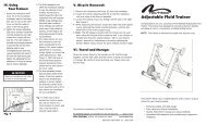
▲! WARNING<br />
Improper installation or use of the brakes may result in a loss of control and serious<br />
injury or even death. Because each bicycle handles differently, practice riding and<br />
braking technique away from traffic to familiarize yourself with brake operation and<br />
bicycle control characteristics. Before using brakes, test tightness of mounting nuts,<br />
brake shoe-fixing bolts, and cable-fixing bolts. If you are not sure how to properly<br />
install or use your brakes, consult your professional bicycle dealer.<br />
<strong>Long</strong> <strong>Reach</strong> <strong>Calipers</strong><br />
Thank you for your purchase of the <strong>Nashbar</strong> <strong>Long</strong> <strong>Reach</strong> <strong>Calipers</strong>.<br />
Notes:<br />
1. The <strong>Nashbar</strong> <strong>Long</strong> <strong>Reach</strong> calipers<br />
offer a wide range of reach adjustment<br />
– from 41mm to 56mm – and<br />
are designed to satisfy a variety of fit<br />
applications.<br />
2. These brake calipers are sold as a<br />
complete set, which includes one<br />
caliper designed for the front wheel<br />
and one caliper designed for the<br />
rear wheel.<br />
3. Be sure to use the appropriate caliper<br />
for each wheel. The mounting bolt (I)<br />
on the rear caliper is shorter than the<br />
mounting bolt on the front caliper.<br />
For Technical support, call 1-800-888-2710, M-F 9am-6pm EST<br />
Bike <strong>Nashbar</strong>, 6103 Rt. 446, Canfield,OH 44406<br />
Made in Taiwan<br />
www.<strong>Nashbar</strong>.com<br />
NS-LRB, V.2 – March 2004<br />
4. New cables and new housing are<br />
always recommended when installing<br />
new brakes.<br />
IMPORTANT<br />
These brake calipers are equipped with a quick release lever (D) to facilitate wheel<br />
removal and installation. It is critical for proper brake operation that this lever be fully<br />
CLOSED (down) during use. Before each ride, and especially after installing the front or<br />
rear wheel, check to make sure the quick release lever is in the fully CLOSED position.<br />
See figure 2.<br />
Caliper Installation<br />
1. Remove existing brakes.<br />
2. Identify the brakes and confirm front or rear as decribed in Note 3, above.<br />
3. Slide washer (K) onto mounting bolt before inserting into frame or fork.<br />
4. Insert mounting bolt through hole in frame (for rear caliper) or fork (for front caliper),<br />
then thread mounting nut onto mounting bolt.<br />
5. Adjust caliper so that pads are equidistant from rim, then secure mounting nut to 70-<br />
85 in-lbs. of torque.
Cable Installation<br />
1. Install brake lever and cable system, if not already installed.<br />
2. Grease threads of cable-fixing bolt (H) and threads of cable-adjusting barrel (E).<br />
3. Set cable-adjusting barrel to 3 full turns out from fully-in position.<br />
4. Make sure Q.R. lever (D) is fully down. See figure 2.<br />
5. Thread inner cable through cable-adjusting barrel and cable pinch mechanism (G).<br />
6. Hold brake pads against rim.<br />
7. Draw slack out of cable.<br />
8. Secure cable-fixing bolt to 50-70 in-lbs. of torque. See figure 3.<br />
Fine Tune Brake Pad Position and Clearance<br />
1. Position the brake pads so that the upper edge of the pad is 1-2mm below the<br />
upper edge of the rim.<br />
2. The top corners of pads should be equidistant from top edge of rim.<br />
3. Toe-in each brake pad using the integral beveled washer so that leading edge of<br />
pad strikes rim slightly before trailing end.<br />
4. Tighten brake shoe-fixing bolt (F) to 43-61 in-lbs. of torque.<br />
5. Stress cable system by pulling against lever 10 times with maximum force that<br />
would be used during a panic stop.<br />
6. Readjust brake cable as needed after stressing by threading the cable-adjusting<br />
barrel (E) in to increase clearance, or out to reduce clearance until each pad<br />
clears rim by 1-2mm. See figure 2.<br />
7. Move inner wire through pinch mechanism to adjust clearance if adjusting barrel<br />
cannot move down far enough, or must be moved out more than 4mm from bottomed,<br />
to achieve proper clearance.<br />
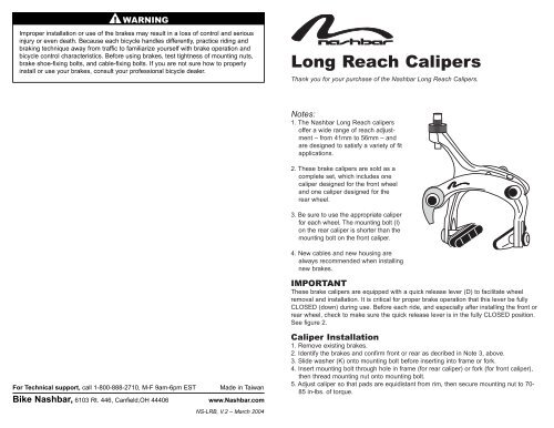
Figure 1<br />
F<br />
K<br />
B<br />
E<br />
G<br />
H<br />
I<br />
J<br />
Adjust Pad Centering<br />
1. Operate brake and observe whether brake tends to push rim to one side, or<br />
whether one pad reaches rim before the other. If either condition exists, centering<br />
adjustment is needed.<br />
2. Turn centering screw (C) clockwise to move the brake’s right pad (as seen when<br />
facing brake) away from rim and left pad toward rim.<br />
3. Turn centering screw counterclockwise to move brake’s right pad (as seen when<br />
facing brake) toward rim and left pad away from rim. See figure 2.<br />
Parts . . . . . .Description<br />
A . . . . . . . . . . . . . . Caliper arms<br />
B . . . . . . . . . . . . . . Brake pads<br />
C . . . . . . . . . . . . . Centering screw<br />
D . . . . . . . . . . . . . Quick-release (Q.R.) lever<br />
E . . . . . . . . . . . . . . Cable-adjusting barrel<br />
F . . . . . . . . . . . . . . Brake shoe-fixing bolt<br />
G . . . . . . . . . . . . . Cable pinch mechanism<br />
H . . . . . . . . . . . . . Cable-fixing bolt<br />
I . . . . . . . . . . . . . . Mounting bolt<br />
J . . . . . . . . . . . . . . Mounting nut<br />
K . . . . . . . . . . . . . . Washer<br />
D<br />
Figure 2<br />
A<br />
C<br />
Philips screwdriver<br />
5mm Hex<br />
wrench<br />
(50-70in.-lbs.)<br />
Figure 3