5219 Polyphase, Multi-Rate Credit Meter Externally ... - Meterspec
5219 Polyphase, Multi-Rate Credit Meter Externally ... - Meterspec
5219 Polyphase, Multi-Rate Credit Meter Externally ... - Meterspec

You also want an ePaper? Increase the reach of your titles
YUMPU automatically turns print PDFs into web optimized ePapers that Google loves.
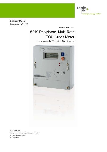
Electricity <strong>Meter</strong>s<br />
Residential BS / IEC<br />
British Standard<br />
<strong>5219</strong> <strong>Polyphase</strong>, <strong>Multi</strong>-<strong>Rate</strong><br />
TOU <strong>Credit</strong> <strong>Meter</strong><br />
User Manual & Technical Specification<br />
Date: 20/11/09<br />
Filename: <strong>5219</strong> User Manual Version 4.0.doc<br />
Q Pulse Number:IB048<br />
© Landis+Gyr
Page 2 of 32 Issue: 4.0 Revision History<br />
Revision History<br />
Index Date Comments<br />
4 18.11.2008 Revised manual to new branding guidelines and layout<br />
Copyright notice<br />
The material in this document is the property of Landis+Gyr. Our products are under continual<br />
improvement and we reserve the right to make changes without prior notice.<br />
Landis+Gyr<br />
1 Lysander Drive,<br />
Northfields Industrial Estate,<br />
Market Deeping,<br />
Peterborough<br />
PE6 8FB<br />
www.landisgyr.com<br />
© Landis+Gyr <strong>5219</strong> <strong>Polyphase</strong>, <strong>Multi</strong>-<strong>Rate</strong> <strong>Credit</strong> <strong>Meter</strong> <strong>Externally</strong> Switched – User Manual & Technical Specification
Table of Contents Issue: 4.0 Page 3 of 32<br />
Table of Contents<br />
1 Introduction____________________________________________________________ 5<br />
1.1 Purpose _________________________________________________________________ 5<br />
1.2 <strong>Meter</strong> Overview ___________________________________________________________ 5<br />
1.3 Reference Standards _______________________________________________________ 5<br />
2 Safety _________________________________________________________________ 6<br />
2.1 Safety Information ________________________________________________________ 6<br />
2.2 Responsibilities ___________________________________________________________ 6<br />
2.3 Safety Regulations _________________________________________________________ 7<br />
3 Operational Functions ___________________________________________________ 8<br />
3.1 Measurement _____________________________________________________________ 8<br />
3.2 Registers ________________________________________________________________ 8<br />
3.3 Reverse / Export Energy Registration __________________________________________ 8<br />
3.3.1 Reverse Energy Detection ___________________________________________________ 8<br />
3.3.2 Import Energy Registration __________________________________________________ 9<br />
3.3.3 Export Energy Registration __________________________________________________ 9<br />
3.3.4 Unidirectional Registration __________________________________________________ 9<br />
3.4 Reactive Energy ___________________________________________________________ 9<br />
3.5 Maximum Demand_________________________________________________________ 9<br />
3.5.1 Rolling Maximum Demand__________________________________________________ 10<br />
3.5.2 Slab Maximum Demand____________________________________________________ 10<br />
3.5.3 Quality of Supply _________________________________________________________ 11<br />
3.6 Phase Indication _________________________________________________________ 11<br />
3.7 Factory / <strong>Meter</strong> Serial Number ______________________________________________ 11<br />
3.8 <strong>Meter</strong> Memory ___________________________________________________________ 11<br />
3.9 Anti-creep ______________________________________________________________ 11<br />
3.10 Temperature Range_______________________________________________________ 11<br />
3.11 Power Supply ____________________________________________________________ 12<br />
3.12 Influence of Supply Voltage ________________________________________________ 12<br />
4 Core User Interfaces ___________________________________________________ 13<br />
4.1 Display _________________________________________________________________ 13<br />
4.2 Energy Registration _______________________________________________________ 13<br />
4.3 Optical Interface _________________________________________________________ 13<br />
5 Optional Functions _____________________________________________________ 14<br />
5.1 Introduction _____________________________________________________________ 14<br />
5.2 Pulsed Output ___________________________________________________________ 14<br />
5.3 External <strong>Rate</strong> Switching ___________________________________________________ 14<br />
<strong>5219</strong> <strong>Polyphase</strong>, <strong>Multi</strong>-<strong>Rate</strong> <strong>Credit</strong> <strong>Meter</strong> <strong>Externally</strong> Switched- User Manual & Technical Specification © Landis+Gyr
Page 4 of 32 Issue: 4.0 Table of Contents<br />
5.4 No-Power Read _________________________________________________________ 14<br />
5.5 Mode-C Data Readout ____________________________________________________ 15<br />
5.6 Inductive Serial Data Port _________________________________________________ 15<br />
5.7 Calibration Lock _________________________________________________________ 16<br />
5.8 Voltage Isolation Switches _________________________________________________ 16<br />
5.9 Landis+Gyr Switch Mode Power Supply ______________________________________ 16<br />
5.10 Push Button’s ___________________________________________________________ 16<br />
6 Installation ____________________________________________________________ 17<br />
6.1 Construction ____________________________________________________________ 17<br />
6.2 Connections ____________________________________________________________ 17<br />
6.3 <strong>Meter</strong> Terminals _________________________________________________________ 18<br />
6.4 Sealing Arrangement _____________________________________________________ 19<br />
7 Technical Summary ____________________________________________________ 20<br />
7.1 Technical Facts __________________________________________________________ 20<br />
7.2 Dimensions _____________________________________________________________ 21<br />
8 Maintenance and Service ________________________________________________ 22<br />
8.1 <strong>Meter</strong> Check ____________________________________________________________ 22<br />
8.2 <strong>Meter</strong> Testing ___________________________________________________________ 22<br />
8.3 Post Installation Configuration Changes ______________________________________ 22<br />
9 Measures in the Event of Faults __________________________________________ 23<br />
9.1 Operating Faults _________________________________________________________ 23<br />
9.2 Disconnecting the <strong>Meter</strong> __________________________________________________ 23<br />
9.3 Repairing the <strong>Meter</strong> ______________________________________________________ 23<br />
10 Decommissioning and Disposal __________________________________________ 25<br />
11 Glossary of Terms and Standards _________________________________________ 26<br />
11.1 Acronyms ______________________________________________________________ 26<br />
11.2 Measurement Units ______________________________________________________ 26<br />
12 Appendices ___________________________________________________________ 27<br />
12.1 Appendix A – Inductive Serial Data Port ______________________________________ 27<br />
12.2 Appendix B – Readout Data ________________________________________________ 28<br />
12.3 Appendix C – Display Options ______________________________________________ 29<br />
12.3.1 Display Examples ________________________________________________________ 30<br />
12.4 Appendix D – Registers ___________________________________________________ 31<br />
© Landis+Gyr <strong>5219</strong> <strong>Polyphase</strong>, <strong>Multi</strong>-<strong>Rate</strong> <strong>Credit</strong> <strong>Meter</strong> <strong>Externally</strong> Switched – User Manual & Technical Specification
Introduction Issue: 4.0 Page 5 of 32<br />
1 Introduction<br />
Introducing the <strong>5219</strong> <strong>Polyphase</strong> meter<br />
1.1 Purpose<br />
This manual covers the operation, installation instructions and technical<br />
specifications of the <strong>5219</strong> <strong>Polyphase</strong> credit meter. The <strong>5219</strong> range includes<br />
single rate, externally switched multirate, and single or multirate pulse<br />
output variants.<br />
1.2 <strong>Meter</strong> Overview<br />
1.3 Reference Standards<br />
The meter is a whole current credit meter, capable of measuring Active<br />
(kWh) (class 1.0) and Reactive energy (KVArh) (class 2.0).<br />
The <strong>Meter</strong> has 3 measuring elements capable of being configured as<br />
• 3 phase, 4 wire.<br />
• 3 phase, 3 wire.<br />
• 2 phases of 3 phase, 4 wire.<br />
• Single phase, 2 wire.<br />
• Single phase, 3 wire.<br />
In some of the above configurations the meters is able to act as a true<br />
multi- voltage measurement device, remaining class accurate between<br />
120Vac and 240Vac. (Both limits +15% to –20%)<br />
The meter has been given a 20 year certification life by OFGEM, the<br />
regulator for the UK. This is based on a reliability of better than 97% over<br />
20 years calculated using an OFGEM model.<br />
An LCD display’s all of the meter’s data.<br />
1. BS EN62053 – 21:2003 Static meters for active energy. (Classes 1 &<br />
2)<br />
2. BS EN62052 – 11:2003 Alternating current static watt-hour meters<br />
for active energy. (Classes 1 & 2)<br />
3. BS5685: 1979: Part 1 Specification class 0.5, 1.0 and 2.0 Single<br />
phase and <strong>Polyphase</strong>, single rate and multi-rate watt-hour meters.<br />
4. IEC62056-21:2002 Data Exchange for <strong>Meter</strong> Reading, Tariff and<br />
Load Control. Direct Local Exchange<br />
5. SI1566: 1998 The <strong>Meter</strong>s (Certification) Regulations 1998;<br />
6. DIN 43 857<br />
Part 2 1978 Principal dimensions for <strong>Polyphase</strong> <strong>Meter</strong>s<br />
Part 4 1974 Principal dimensions of the terminal cover for<br />
<strong>Polyphase</strong> <strong>Meter</strong>s<br />
<strong>5219</strong> <strong>Polyphase</strong>, <strong>Multi</strong>-<strong>Rate</strong> <strong>Credit</strong> <strong>Meter</strong> <strong>Externally</strong> Switched– User Manual & Technical Specification © Landis+Gyr
Page 6 of 32 Issue: 4.0 Safety<br />
2 Safety<br />
2.1 Safety Information<br />
Attention is drawn as follows in the individual chapters of this user manual<br />
with classified word symbols and pictographs to the relevant danger level,<br />
i.e. the severity and probability of any danger:<br />
Definition of Danger<br />
This symbol is used to indicate a possibly dangerous situation which could<br />
result in severe physical injury or a fatality.<br />
Definition of Warning<br />
This symbol is used to indicate a possibly dangerous situation which could<br />
result in minor physical injury or material damage.<br />
Definition of Note<br />
This symbol is used to indicate general details and other useful information.<br />
2.2 Responsibilities<br />
In addition to the danger level, all safety information also describes the type<br />
and source of the danger, it’s possible consequences and measures to<br />
counteract the danger.<br />
The owner of the meter – normally the utility – is responsible that all<br />
persons engaged on work with the meter:<br />
• Have read and understood the relevant sections of this user<br />
manual.<br />
• Are sufficiently qualified for the work to be performed.<br />
• Strictly observe the safety regulations and the operating information<br />
in the individual chapters.<br />
In particular, the owner of the meter bears responsibility for the protection<br />
of persons, prevention of material damage and the training of personnel<br />
(Landis+Gyr. provides training courses for this purpose on specific<br />
equipment; please contact the relevant agent if interested).<br />
© Landis+Gyr <strong>5219</strong> <strong>Polyphase</strong>, <strong>Multi</strong>-<strong>Rate</strong> <strong>Credit</strong> <strong>Meter</strong> <strong>Externally</strong> Switched – User Manual & Technical Specification
Safety Issue: 4.0 Page 7 of 32<br />
2.3 Safety Regulations<br />
The following safety regulations must be observed at all times:<br />
• This equipment does not contain a disconnection device. Means for<br />
disconnection from the supply must be provided as part of the<br />
building installation. Do not work on the equipment unless the<br />
supply is disconnected. If disconnection is done by removal of fuses<br />
or other cut-outs, the removed disconnection devices must be kept<br />
secure from replacement while work is performed. If disconnection<br />
is provided by a switch, the switch shall conform to the requirements<br />
of IEC 947-1 and IEC 947-3 or equivalent.<br />
• This equipment does not contain an over current protection device.<br />
Over current protection must be provided as part of the building<br />
installation. Maximum over current device rating is 125 Amp at 415<br />
Volts, conforming to the requirements of BS1361, or equivalent.<br />
• Only suitably trained and qualified personnel shall be allowed to<br />
work on the equipment. Local safety standards shall be observed<br />
and shall take precedence over these regulations in points of<br />
conflict.<br />
• The meter must be held securely during installation. They can<br />
cause injuries if dropped.<br />
• Any meter that has fallen must not be installed, even if no damage<br />
is apparent, but must be returned for testing to the service and<br />
repair department responsible (or the manufacturer). Internal<br />
damage can result in functional disorders or short-circuits.<br />
• The meter must on no account be cleaned with running water or<br />
with high-pressure devices. Water penetration can cause shortcircuits.<br />
• The meter terminal cover should be secured in place before any<br />
load is applied.<br />
• To avoid overheating, the meter must be connected using<br />
appropriate cable sizes.<br />
o Currents up to 60A a cable with minimum 16mm2 cross-section<br />
area.<br />
o Currents up to 100A a cable with minimum 25mm2 crosssection<br />
area.<br />
o Currents up to 125A a cable with minimum 35mm2 crosssection<br />
area.<br />
<strong>5219</strong> <strong>Polyphase</strong>, <strong>Multi</strong>-<strong>Rate</strong> <strong>Credit</strong> <strong>Meter</strong> <strong>Externally</strong> Switched– User Manual & Technical Specification © Landis+Gyr
Page 8 of 32 Issue: 4.0 Operational Functions<br />
3 Operational Functions<br />
3.1 Measurement<br />
The standard operational functions of the <strong>5219</strong><br />
The meter has been designed to work with a wide range of voltages,<br />
current ranges, and frequency options. Please refer to the technical<br />
specifications for details.<br />
The meter measures and registers kWh to class 1.0 and KVArh to class<br />
2.0. There is a meter constant LED mounted on the front panel of the meter<br />
for testing purposes, pulsing at a rate of 1,000 pulses per kWh.<br />
The meter may be configured to register Import and Export energy. See<br />
section Reverse / Export Energy Registration.<br />
An option is available to ‘enable’ kVArh registration so that meters can be<br />
supplied either ‘Active’ only or ‘Active / Reactive’. See section Reactive<br />
energy.<br />
3.2 Registers<br />
The meter energy registers have the range 000000.000 - 999999.999 kWh.<br />
The registers are displayed to a maximum of 2 decimal places unless<br />
programmed via the Flag Port (see User Interfaces) to 3 decimal places for<br />
testing purposes only. A complete table of registers is shown in the<br />
appendix.<br />
3.3 Reverse / Export Energy Registration<br />
3.3.1 Reverse Energy Detection<br />
The meter is able to recognise reverse energy and deal with it according to<br />
the configuration requested by the customer. The options include reverse<br />
energy detection ‘rEd’, import registration only, unidirectional registration<br />
and export energy registration. This configuration is done in the factory.<br />
The customer may have the meter configured such that when reverse<br />
energy is detected the reverse energy warning shown below is displayed.<br />
This display will alternate between its normal display and the warning<br />
message. This reverse energy power threshold may be set between 0.23<br />
kW and 35 kW, and is calculated over a period of 10 seconds. This<br />
threshold is factory configurable and applies irrespective of what forward<br />
power may be present during the same period of time.<br />
The warning message can only be reset by LANDIS+GYR software or the<br />
use of a HHU using the optical communication port on the front of the<br />
meter. When clearing down the reverse energy detected ‘rEd message’ and<br />
reverse Wh registers, the capacitive kVArh registers will not be affected.<br />
1 2<br />
3 4<br />
Figure 1 rEd Message<br />
© Landis+Gyr <strong>5219</strong> <strong>Polyphase</strong>, <strong>Multi</strong>-<strong>Rate</strong> <strong>Credit</strong> <strong>Meter</strong> <strong>Externally</strong> Switched – User Manual & Technical Specification
Operational Functions Issue: 4.0 Page 9 of 32<br />
The reverse energy detection is available in the registry modes below.<br />
3.3.2 Import Energy Registration<br />
3.3.3 Export Energy Registration<br />
3.3.4 Unidirectional Registration<br />
3.4 Reactive Energy<br />
In this configuration only forward Watt hours consumed are noted and<br />
added to the Total kWh register.<br />
The consumption of each phase is added into the reverse or forward<br />
registers as appropriate.<br />
For example:<br />
Phase R 5A forward, Phase S 5A forward, Phase T 10A reverse will result<br />
in both forward and reverse registers increasing at the same rate. It will not<br />
result in zero power being registered.<br />
The impulse LED may be configured to flash when any power is registered,<br />
forward or reverse.<br />
The output from each phase will be added directly to the forward registers<br />
regardless of the direction of the power.<br />
For the example given above the current consumption will be identified as<br />
20A and the impulse LED will flash accordingly.<br />
The <strong>5219</strong> can be configured in the factory to measure and register reactive<br />
energy. The reactive energy consumed will be registered as inductive or<br />
capacitive as appropriate. The Total Reactive energy register can be<br />
configured to show the sum of inductive and capacitive reactive energy or<br />
the difference between them.<br />
The 'Total kVArh' display message will therefore show:<br />
Total Inductive kVArh + Total Capacitive kVArh.<br />
Or<br />
3.5 Maximum Demand<br />
Total Inductive kVArh - Total Capacitive kVArh.<br />
Maximum demand may be configured to work in either rolling mode as<br />
illustrated below or slab. The maximum demand value in either case may<br />
be measured in one of the following, kW, kVAr, or kVA.<br />
The MD register has a range 00.00 to 99.99.<br />
The meter stores the most previous Total MD value in memory and it may<br />
be displayed if required.<br />
The meter will measure and display the current MD values assigned to the<br />
appropriate rates in the multirate variant.<br />
The MD may be reset via the optical port using Landis+Gyr Software or<br />
HHU, or front fascia mounted and seal-able MD button.<br />
<strong>5219</strong> <strong>Polyphase</strong>, <strong>Multi</strong>-<strong>Rate</strong> <strong>Credit</strong> <strong>Meter</strong> <strong>Externally</strong> Switched– User Manual & Technical Specification © Landis+Gyr
Page 10 of 32 Issue: 4.0 Operational Functions<br />
The display for maximum demand is shown below. KW is for illustration<br />
only and will display as kVAr, kVA etc as appropriate.<br />
1 2 3<br />
KW<br />
Figure 2 MD Display<br />
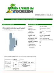
3.5.1 Rolling Maximum Demand<br />
Maximum Demand is calculated on a fifteen minute rolling period. Every<br />
minute the power usage of the last 15 minutes is calculated and multiplied<br />
by four to give the equivalent demand for a one-hour period. If this value is<br />
larger than the previous largest stored value, this value replaces it in the<br />
Maximum Demand register.<br />
Rolling Maximum Demand provides better accuracy than slab MD. As<br />
illustrated below the highest demand value will be measured this way, as<br />
the peak of demand will be captured by the rolling 15-minute period.<br />
Figure 3 Rolling Maximum Demand<br />
10.00<br />
8.00<br />
kW<br />
6.00<br />
4.00<br />
2.00<br />
0.00<br />
1 2 3 4 5 6 7 8 9 101112131415161718192021222324252627282930<br />
Minutes<br />
3.5.2 Slab Maximum Demand<br />
On power up, the MD register will remain at zero until 15 minutes have<br />
passed. Maximum demand values will not be calculated until the buffer<br />
holds complete data for the preceding 15 minutes.<br />
When an MD store occurs (using the MD reset button), MD will remain<br />
zeroed until 15 minutes have passed and the buffer holds data for the 15<br />
minutes since the last MD store.<br />
This maximum demand method works by calculating the maximum demand<br />
over fixed customer specifiable periods of minutes. These periods must be<br />
factors of 60 minutes. The first period commences on power up of the<br />
meter and continues thereafter until power fail or MD reset.<br />
© Landis+Gyr <strong>5219</strong> <strong>Polyphase</strong>, <strong>Multi</strong>-<strong>Rate</strong> <strong>Credit</strong> <strong>Meter</strong> <strong>Externally</strong> Switched – User Manual & Technical Specification
Operational Functions Issue: 4.0 Page 11 of 32<br />
3.5.3 Quality of Supply<br />
3.6 Phase Indication<br />
3.7 Factory / <strong>Meter</strong> Serial Number<br />
3.8 <strong>Meter</strong> Memory<br />
On powerfail the rising MD value of the current MD period is integrated over<br />
the MDP and stored. If this value is larger than the previous largest MD<br />
value, on power up the new largest value will become the stored MD value.<br />
On MD reset the current MD value is cleared down, and a new MDP<br />
started. The value at reset is stored as the most previous MD total.<br />
The meter may be customer specified to measure and display RMS voltage<br />
and current.<br />
• The Instantaneous Voltage Register has a range 000 to 999 Vac<br />
• The Instantaneous Current Register has a range 000 to 999 Amps.<br />
The Display will indicate phase voltage present on each phase with the<br />
display of the following symbols. Ø1, Ø2, Ø3.<br />
The voltage that the symbol appears can be configured at the factory<br />
between 0 and 240V.<br />
Additionally the phase symbol can be configured to flash to indicate reverse<br />
connection or reverse energy detection.<br />
There is the ability within the meter to store a 46-digit serial number. The<br />
most significant 20 digits of which can be laser printed to the meters front<br />
fascia.<br />
All the meters data is recorded in Ferroelectric Random Access Memory<br />
(FRAM) under the control of the microprocessor. All the kWh and kVAr<br />
registers are stored in the FRAM and will are updated periodically and on<br />
power-fail. The FRAM is able to be re-written and is stable (no memory<br />
losses) throughout the life of the meter.<br />
3.9 Anti-creep<br />
Below starting current, the meter will enter into an anti-creep mode. In this<br />
state the meter registration LED is permanently lit and the registers do not<br />
increment. The LED remains lit until the meter current is increased in either<br />
the forward or reverse direction beyond the starting current. See the<br />
technical specification section for details of Ib.<br />
3.10 Temperature Range<br />
Operating range: 10°C to 45°C<br />
Limit range of operation: 25°C to 60°C<br />
Storage range*: 25°C to 70°C<br />
*Maximum period of 6 hours at the extremes of this temperature range.<br />
<strong>5219</strong> <strong>Polyphase</strong>, <strong>Multi</strong>-<strong>Rate</strong> <strong>Credit</strong> <strong>Meter</strong> <strong>Externally</strong> Switched– User Manual & Technical Specification © Landis+Gyr
Page 12 of 32 Issue: 4.0 Operational Functions<br />
3.11 Power Supply<br />
This complies with IEC 62052-11.<br />
3.12 Influence of Supply Voltage<br />
The power supply for the meter electronics is derived from all 3 phases.<br />
The meter will continue to operate in the event of a loss of any one or two<br />
phases.<br />
<strong>Rate</strong>d Voltage: 220 / 380 Vac 240 / 415 Vac<br />
Operating Voltage Range: +15% to 20%<br />
The meter complies with IEC 62052-11: Section 7.1.2. and is tested by<br />
NMI.<br />
Current Range:<br />
Frequency:<br />
Power Burden:<br />
5 to125 Amps<br />
50Hz<br />
Less than 2 watts<br />
© Landis+Gyr <strong>5219</strong> <strong>Polyphase</strong>, <strong>Multi</strong>-<strong>Rate</strong> <strong>Credit</strong> <strong>Meter</strong> <strong>Externally</strong> Switched – User Manual & Technical Specification
Core User Interfaces Issue: 4.0 Page 13 of 32<br />
4 Core User Interfaces<br />
The inputs and outputs of the <strong>5219</strong><br />
4.1 Display<br />
All the meters data is displayed on a LCD on which the size of each value<br />
character has a height of 8mm and a width of 3.5mm giving an overall area<br />
of 28mm² per character. The LCD has a minimum life expectancy of 20<br />
years.<br />
The meter LCD display is designed to have a high angle of readability.<br />
The meter shows six significant digits with a customer configurable number<br />
of decimal places, 0, 1 or 2.<br />
The display cycle advance is factory configurable to be:<br />
• An auto cycling system that shows the active rate “flashing” and<br />
scrolls through each of the displays according to a configurable time<br />
from 1 to 10 seconds.<br />
• By using a cycle display button mounted on the meters face.<br />
• A combination of both modes. The meter will auto cycle, with the<br />
button providing a means of moving to the next display immediately.<br />
OBIS display legends are available on request. This is a factory<br />
configurable option. See Appendix.<br />
A detailed drawing of the LCD is shown below. Further display illustrations<br />
are shown in the appendix, along with a table of all available displays.<br />
1 2 3<br />
1<br />
2<br />
3<br />
4<br />
5<br />
KWh<br />
kvarh<br />
kVAh<br />
vrms Irms RC RI<br />
Figure 4 LCD Format<br />
4.2 Energy Registration<br />
4.3 Optical Interface<br />
Separate kWh and kVArh indicator LED’s are present on the front aspect of<br />
the meter. The pulse value is identified on the meters fascia, at 1000 pulses<br />
per kWh/kVArh. The pulses can be used for checking the meter calibration.<br />
The meter includes a FLAG optical interface based upon IEC62056-<br />
21:2002. This optical interface supports the IEC1107 mode-c readout<br />
protocol. The baud rate for communication via the optical interface can be<br />
set in the meter. See technical summary for details.<br />
<strong>5219</strong> <strong>Polyphase</strong>, <strong>Multi</strong>-<strong>Rate</strong> <strong>Credit</strong> <strong>Meter</strong> <strong>Externally</strong> Switched– User Manual & Technical Specification © Landis+Gyr
Page 14 of 32 Issue: 4.0 Optional Functions<br />
5 Optional Functions<br />
5.1 Introduction<br />
5.2 Pulsed Output<br />
Optional user interfaces and additional functionality available in the <strong>5219</strong>.<br />
The features in this section are in addition to the basic <strong>5219</strong> model. These<br />
options must be requested when obtaining meter availability and price from<br />
Landis+Gyr at the outset of the ordering process.<br />
The meter has a pulsed output function, configurable through the optical<br />
interface (FLAG) port. The pulse output meets with regulation IEC62053-<br />
31: 1998 Class B. The output ratings are shown in the technical<br />
specification.<br />
The meter has the option of one voltage free pulse output for kWh. The<br />
pulse output is configurable between 1 to 1000 pulses per kWh, (where<br />
1000/kWh = whole number) with pulse duration of 40 to 500 mS in 20 mS<br />
steps. Output format is as shown below; using terminals A and B (figure 6).<br />
kWh<br />
+<br />
_<br />
Figure 5 Pulse Output Format<br />
5.3 External <strong>Rate</strong> Switching<br />
5.4 No-Power Read<br />
The multi-rate variants are externally rate switched. The active rate is<br />
selected externally by applying a signal; neutral or live, to the rate switching<br />
inputs. The active rate is dependant on the number of rates the meter is<br />
configured for 1, 2, 3, or 4 and the switching protocol the customer has<br />
specified. Signal is applied to 1 auxiliary terminal, an alternative auxiliary<br />
terminal, or both simultaneously to achieve 4 switched rates.<br />
Additionally the meter may be taken with a combination of pulse output and<br />
external rate switching. In this circumstance 1 auxiliary terminal is used for<br />
rate switching and the meter may only be configured as a 2-rate meter.<br />
A meter variant is available that addresses the need of some customers to<br />
be able to make meter readings while the network voltage is off. A front<br />
fascia mounted push button is fitted which when pressed and held for 3<br />
seconds latches the internal power circuit on. This powers the display,<br />
© Landis+Gyr <strong>5219</strong> <strong>Polyphase</strong>, <strong>Multi</strong>-<strong>Rate</strong> <strong>Credit</strong> <strong>Meter</strong> <strong>Externally</strong> Switched – User Manual & Technical Specification
Optional Functions Issue: 4.0 Page 15 of 32<br />
5.5 Mode-C Data Readout<br />
5.6 Inductive Serial Data Port<br />
cycle display button, and optical readout port temporarily and allows a 45<br />
second period to read the registers, via display and or FLAG port readout.<br />
After approximately 45 seconds the meter powers off regardless of whether<br />
the button is still depressed, and will remain powered off for a period of 45<br />
minutes. This mechanism protects the meters internal power source from<br />
being fully discharged by constant button pressing.<br />
The displays available during this function are customer specifiable.<br />
A secondary back-up power source other than the RTC back-up battery is<br />
used for this purpose.<br />
IEC1107 readout mode C is available via the optical FLAG port. The<br />
enabled functions of the meter such as Export kWh registers, kVArh<br />
registers, and maximum demand registers are supported and available<br />
within this data stream. The conventions for the data are shown in the<br />
appendix. The speed of the data readout is the same as for FLAG<br />
communications, that is, 9600 baud.<br />
The meter incorporates an Inductive Serial Data Port that transmits data<br />
wirelessly. See table of data in the appendix.<br />
This allows meter functionality to be extended at a future date by the<br />
addition of an easy to fit add-on module without restricting access to the<br />
optical port for the purpose of meter reading. There is no need for a<br />
physical connection.<br />
Fitting of modules is limited to removing existing terminal cover and<br />
replacing with a module, as illustrated below.<br />
Figure 6 Additional Modules (Future)<br />
The data output provides all information available from within the meter and<br />
would support any module including:<br />
• Prepayment<br />
• Power Line Remote Communication<br />
• Radio and Telephone Communication.<br />
<strong>5219</strong> <strong>Polyphase</strong>, <strong>Multi</strong>-<strong>Rate</strong> <strong>Credit</strong> <strong>Meter</strong> <strong>Externally</strong> Switched– User Manual & Technical Specification © Landis+Gyr
Page 16 of 32 Issue: 4.0 Optional Functions<br />
5.7 Calibration Lock<br />
5.8 Voltage Isolation Switches<br />
If required the meter’s calibration values can be locked with a combination<br />
of hardware and software options. A printed circuit board mounted<br />
hardware switch is fitted and on completion of the factory manufacturing<br />
process this switch is armed by LANDIS+GYR software. FLAG access to<br />
the meter memory locations concerned with calibration values, serial<br />
number etc are then prevented. The terminal cover and top cover need to<br />
be removed for this switch to be reset and access to these locations reinstated.<br />
The requirement during calibration and certification is for voltage and<br />
current signals to be isolated from one another. Some customers require<br />
this ability also for their own verification testing. After testing is complete<br />
and the meter is installed, the ability to do this is prevented by the fitting of<br />
a terminal cover and seals. In markets where additional steps are required<br />
to prevent non-technical losses, isolation switches may be fitted to the pcb,<br />
that once closed prevent any isolation of voltage from current unless the<br />
meter seals are broken and the top cover removed.<br />
Additionally or alternatively mechanical bungs may be fitted behind the<br />
terminal cover that serves the same purpose of preventing isolation of<br />
voltage from current.<br />
5.9 Landis+Gyr Switch Mode Power Supply<br />
5.10 Push Button’s<br />
The Landis+Gyr switch mode power supply if fitted allows the <strong>5219</strong> to fulfil<br />
the requirement of some markets and local approval bodies for the meter to<br />
function with any 1 phase or neutral disconnected. This allows the meter to,<br />
with balanced loads, move from 3Phase4wire operation to 3phase3wire<br />
automatically with no loss of accuracy. This feature may prove useful in<br />
some areas of industry where a provision for neutral connection is left off<br />
the local distribution system.<br />
One front panel push button may be provided if required to enable manual<br />
interaction with the display cycle. That is the display list may be read by<br />
scrolling through 1 display with each button press.<br />
This same push button may also be used to operate the no power read<br />
functionality if this option has been fitted.<br />
© Landis+Gyr <strong>5219</strong> <strong>Polyphase</strong>, <strong>Multi</strong>-<strong>Rate</strong> <strong>Credit</strong> <strong>Meter</strong> <strong>Externally</strong> Switched – User Manual & Technical Specification
Installation Issue: 4.0 Page 17 of 32<br />
6 Installation<br />
6.1 Construction<br />
6.2 Connections<br />
Construction, Mounting and wiring of the <strong>5219</strong><br />
The meter case dimensions conform to the following two standards,<br />
BS5685: 1979: Part 1 and DIN 43 857: 1978: Part 2.The terminal cover<br />
governed by DIN 43 857: 1974: Part 4. For DIN meters the meter will be<br />
supplied with a separate clip-in device to make the design meet the DIN<br />
Standard.<br />
The <strong>Meter</strong> has a double insulated case which meets the requirements of<br />
BS5685 and is manufactured from the following materials:<br />
Base - Flame Retardant Polycarbonate<br />
Top – Polycarbonate<br />
Window - UV Stabilised Polycarbonate<br />
Terminal Cover – Polycarbonate<br />
Dimensions follow in the appendix.<br />
The <strong>Meter</strong> has 3 measuring elements capable of being configured as:<br />
Single phase 2 wire<br />
ELEMENT<br />
A<br />
ELEMENT<br />
B<br />
ELEMENT<br />
C<br />
N<br />
N<br />
L1<br />
SUPPLY<br />
LOAD<br />
L1<br />
Single phase 3 wire<br />
M/E A<br />
M/E B<br />
M/E C<br />
N<br />
L1 A<br />
L1 B<br />
SUPPLY<br />
N<br />
L1 A<br />
L1 B<br />
LOAD<br />
<strong>5219</strong> <strong>Polyphase</strong>, <strong>Multi</strong>-<strong>Rate</strong> <strong>Credit</strong> <strong>Meter</strong> <strong>Externally</strong> Switched– User Manual & Technical Specification © Landis+Gyr
Page 18 of 32 Issue: 4.0 Installation<br />
2 phases of 3 phase 4 wire<br />
M/E A<br />
M/EB<br />
M/E C<br />
N<br />
L(1,2,3)<br />
L(3,1,2)<br />
SUPPLY<br />
3 phase 4 wire<br />
LOAD<br />
N<br />
L(1,2,3)<br />
L(3,1,2)<br />
M/E A<br />
M/E B<br />
M/E C<br />
N<br />
L1<br />
L2<br />
L3<br />
SUPPLY<br />
LOAD<br />
N<br />
L1<br />
L2<br />
L3<br />
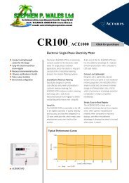
6.3 <strong>Meter</strong> Terminals<br />
The main current terminals and auxiliary terminals are manufactured from<br />
solid brass to the dimensions and pitch outlined in BS5685: 1979: Part 1<br />
and DIN 43 857: 1978: Part 2.<br />
Figure 7 - Terminal Arrangement Photograph<br />
Figure 8 - Terminal Arrangement Plan<br />
For Pulse Output (P/O) only models: Terminals A and B - pulse output<br />
For <strong>Externally</strong> Switched only models: Terminals A and B - external switches<br />
(4 rates)<br />
© Landis+Gyr <strong>5219</strong> <strong>Polyphase</strong>, <strong>Multi</strong>-<strong>Rate</strong> <strong>Credit</strong> <strong>Meter</strong> <strong>Externally</strong> Switched – User Manual & Technical Specification
Installation Issue: 4.0 Page 19 of 32<br />
6.4 Sealing Arrangement<br />
For <strong>Externally</strong> Switched and P/O models: Terminals A and B – pulse<br />
output, terminal D – external switch (2 rates).<br />
The meter is sealed conventionally, using sealing wires and the appropriate<br />
seal for the intended market. The meter can be sealed for life if the<br />
customer requests this service.<br />
<strong>5219</strong> <strong>Polyphase</strong>, <strong>Multi</strong>-<strong>Rate</strong> <strong>Credit</strong> <strong>Meter</strong> <strong>Externally</strong> Switched– User Manual & Technical Specification © Landis+Gyr
Page 20 of 32 Issue: 4.0 Technical Summary<br />
7 Technical Summary<br />
7.1 Technical Facts<br />
The technical specifications of the <strong>5219</strong><br />
System Voltage Three element meters 240Vac Phase to Neutral<br />
230Vac Phase to Neutral<br />
220Vac Phase to Neutral 120Vac<br />
Phase to Neutral<br />
Supply variation +15% to -20%<br />
Current (Base) Direct Connection Ib 5A, 10A, 15A, 20A<br />
Current (Max) Imax 80A, 100A, 105A, 120A, 125A.<br />
Starting Current (IEC) 0.4% of Ib<br />
Max measuring range (IEC) 20mA up to 125A<br />
Typically 15mA for a balanced load<br />
Measuring Accuracy IEC 62053-21 Class 1 Active (kWh)<br />
Class 2 & 3 Reactive (kVArh)<br />
Burdens Voltage Circuit @ 230Vac
Technical Summary Issue: 4.0 Page 21 of 32<br />
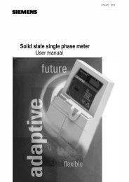
7.2 Dimensions<br />
Figure 9 - Dimensional Drawing of the <strong>5219</strong> <strong>Meter</strong><br />
<strong>5219</strong> <strong>Polyphase</strong>, <strong>Multi</strong>-<strong>Rate</strong> <strong>Credit</strong> <strong>Meter</strong> <strong>Externally</strong> Switched– User Manual & Technical Specification © Landis+Gyr
Page 22 of 32 Issue: 4.0 Maintenance and Service<br />
8 Maintenance and Service<br />
8.1 <strong>Meter</strong> Check<br />
8.2 <strong>Meter</strong> Testing<br />
While it isn’t necessary, under normal circumstances, to perform any<br />
maintenance on the installed meter, the following are check points that<br />
should be observed during scheduled periodic meter visits.<br />
• Is the meter dry and clean, particularly the LCD display and the<br />
optical interface?<br />
• Does the meter display a legible and sensible display? i.e. does the<br />
meter appear in a serviceable condition.<br />
• Check all factory fitted and company fitted seals are in place secure<br />
and intact.<br />
• Observe display for any error messages or notifications<br />
• Confirm that the energy registers have changed to a reasonable<br />
degree since the last visit.<br />
• If irregularities are found, continue as in section 8.<br />
The testing of meters, either random sample or on all meters, should be<br />
carried out periodically according to national regulations. The meter must<br />
be removed as described in section 8.3 and replaced with a meter of similar<br />
type for the duration of the tests.<br />
8.3 Post Installation Configuration Changes<br />
With the aid of a laptop computer or other suitable hand held device a flag<br />
probe and Landis+Gyr specific software, it is possible to amend the factory<br />
configured options of the meter. It is beyond the scope of this manual to<br />
describe in any further detail the procedure. Landis+Gyr sales team would<br />
be happy to discuss specific requirements.<br />
© Landis+Gyr <strong>5219</strong> <strong>Polyphase</strong>, <strong>Multi</strong>-<strong>Rate</strong> <strong>Credit</strong> <strong>Meter</strong> <strong>Externally</strong> Switched – User Manual & Technical Specification
Measures in the Event of Faults Issue: 4.0 Page 23 of 32<br />
9 Measures in the Event of Faults<br />
9.1 Operating Faults<br />
9.2 Disconnecting the <strong>Meter</strong><br />
If the LCD window is illegible or the data readout does not function, the<br />
following points should be checked.<br />
Is the mains voltage present? – Are the preliminary fuses intact?<br />
Has the minimum or maximum recommended ambient temperature been<br />
exceeded?<br />
Is the LCD window clear of all debris? – Not misted over, painted over or<br />
soiled in any way.<br />
If none of the above are causing the fault the meter should be disconnected<br />
as per section 9.2, replaced if required as detailed in section 6 and returned<br />
to Landis+Gyr as described in section 9.3.<br />
Remove preliminary fuses before continuing<br />
The connecting conductors should not be Live when removing the meter.<br />
Electrically Live parts are a life threatening hazard. Preliminary fuses should<br />
be removed and kept in a safe place until all work is complete, where they<br />
cannot be replaced by anyone unnoticed.<br />
9.3 Repairing the <strong>Meter</strong><br />
Proceed as follows:<br />
• Remove the company seal on the terminal cover (if fitted).<br />
• Release the two terminal cover screws and remove terminal cover.<br />
• Check with a suitable voltage testing device that the phase<br />
connections are not live. If they are live then remove the preliminary<br />
fuses and keep in a safe place until all work is complete, where they<br />
cannot be replaced by anyone unnoticed.<br />
• Remove the signal inputs and outputs by releasing the auxiliary<br />
terminal screws.<br />
• Remove the phase connections by releasing the main terminal<br />
screws.<br />
• If required fit a suitable replacement meter as described in section<br />
6.<br />
There are no user serviceable parts inside the meter. Breaking factory<br />
calibration seals will invalidate the calibration status of the meter. In the<br />
event of a meter requiring repair, proceed as follows.<br />
• Remove the meter from the installation as detailed in section 9.2.<br />
• Attach a label, which describes the fault as accurately as possible,<br />
to the meter and include name and contact details of person<br />
responsible in case of inquiries.<br />
<strong>5219</strong> <strong>Polyphase</strong>, <strong>Multi</strong>-<strong>Rate</strong> <strong>Credit</strong> <strong>Meter</strong> <strong>Externally</strong> Switched– User Manual & Technical Specification © Landis+Gyr
Page 24 of 32 Issue: 4.0 Measures in the Event of Faults<br />
• Package the meter to ensure no further damage can occur during<br />
transit.<br />
• Send the meter back to Landis+Gyr.<br />
© Landis+Gyr <strong>5219</strong> <strong>Polyphase</strong>, <strong>Multi</strong>-<strong>Rate</strong> <strong>Credit</strong> <strong>Meter</strong> <strong>Externally</strong> Switched – User Manual & Technical Specification
Decommissioning and Disposal Issue: 4.0 Page 25 of 32<br />
10 Decommissioning and Disposal<br />
The procedure for the safe removal of the meter from the installation is<br />
described in section 9.3. Please ensure that ALL SAFETY PRECAUTIONS<br />
are met before proceeding.<br />
Based on the environmental certificate ISO 14001, the components used to<br />
manufacture the meter can, in the main, be broken down into constituent<br />
parts and sent for suitable recycling or disposal.<br />
The following are general guidelines and should NOT take priority over local<br />
disposal and environmental policies which should be adhered to without<br />
compromise.<br />
Component Parts<br />
Printed Circuit Boards<br />
LCD Display<br />
Metal Components<br />
Plastic Components<br />
Disposal<br />
Treated as per disposal of Electronic Equipment<br />
Sorted and delivered to collective recycling point<br />
Sorted and delivered for re-granulation if at all<br />
possible<br />
<strong>5219</strong> <strong>Polyphase</strong>, <strong>Multi</strong>-<strong>Rate</strong> <strong>Credit</strong> <strong>Meter</strong> <strong>Externally</strong> Switched– User Manual & Technical Specification © Landis+Gyr
Page 26 of 32 Issue: 4.0 Glossary of Terms and Standards<br />
11 Glossary of Terms and Standards<br />
11.1 Acronyms<br />
Acronym<br />
BS<br />
DFS<br />
DIN<br />
ECD<br />
EEPROM<br />
IEC<br />
ISO<br />
LCD<br />
LED<br />
MD<br />
MID<br />
NPR<br />
OFGEM<br />
PTR<br />
RED<br />
Definition<br />
British Standard<br />
Direct Field Sensor<br />
Deutsches Institut für Normung (German Institute For<br />
Standardisation)<br />
External Connection Diagram<br />
Electrically Erasable Programmable Read Only Memory (E2)<br />
International Electrotechnical Commission<br />
International Standards Organisation<br />
Liquid Crystal Display<br />
Light Emitting Diode<br />
Maximum Demand<br />
<strong>Meter</strong>ing Industry Directive<br />
No Power Read<br />
The Office of Gas and Electricity Markets<br />
Photo-transistor<br />
Reverse Energy Detected<br />
11.2 Measurement Units<br />
A<br />
Hz<br />
Iref<br />
Kg<br />
kVAh<br />
kvarh<br />
kWh<br />
mm<br />
mO<br />
ms<br />
Nm<br />
o C<br />
UN<br />
UT<br />
V<br />
Ampere (unit of current)<br />
Hertz (unit of frequency)<br />
MID reference current<br />
Kilogramme (unit of weight)<br />
Kilo Volt Ampere hour<br />
kilo Volt Amps reactive hour<br />
kilo Watt-hour<br />
millimetre (unit of distance)<br />
milliohm (unit of resistance)<br />
millisecond<br />
Newton meter (unit of torque)<br />
Degree Celsius (unit of temperature)<br />
<strong>Rate</strong>d supply voltage of meter<br />
<strong>Rate</strong>d external switch voltage<br />
Volt<br />
© Landis+Gyr <strong>5219</strong> <strong>Polyphase</strong>, <strong>Multi</strong>-<strong>Rate</strong> <strong>Credit</strong> <strong>Meter</strong> <strong>Externally</strong> Switched – User Manual & Technical Specification
Appendices Issue: 4.0 Page 27 of 32<br />
12 Appendices<br />
Additional information for the <strong>5219</strong><br />
12.1 Appendix A – Inductive Serial Data Port<br />
The inductive signal is a 26 KHz square wave modulated by the data<br />
transmitted at 1200 baud. The stream of bytes representing the data is<br />
repeated at 6-second intervals. The table below shows the data available in<br />
the transmission.<br />
Table 1 Inductive Loop Data Stream<br />
Block Description<br />
Block Byte Comment<br />
Count<br />
STX character 1 Start of transmission<br />
<strong>Meter</strong> type and hardware version 8 I.e. AMP<strong>5219</strong>A<br />
Serial number 20 Most significant 20 digits<br />
R1 Import kWh Register (or Total 8 In Wh<br />
kWh in a single rate meter)<br />
R2 Import kWh Register 8 In Wh<br />
R3 Import kWh Register 8 In Wh<br />
R4 Import kWh Register 8 In Wh<br />
R1 Export kWh Register (or Total 8 In Wh<br />
Export kWh in a single rate meter)<br />
R2 Export kWh Register 8 In Wh<br />
R3 Export kWh Register 8 In Wh<br />
R4 Export kWh Register 8 In Wh<br />
R1 Inductive kVArh Register 8 In Wh<br />
R2 Inductive kVArh Register 8 In Wh<br />
R3 Inductive kVArh Register 8 In Wh<br />
R4 Inductive kVArh Register 8 In Wh<br />
R1 Capacitive kVArh Register 8 In Wh<br />
R2 Capacitive kVArh Register 8 In Wh<br />
R3 Capacitive kVArh Register 8 In Wh<br />
R4 Capacitive kVArh Register 8 In Wh<br />
Active <strong>Rate</strong> 2 Identification of<br />
Customer ID 2 Configuration file number<br />
ETX character 1 End of transmission<br />
BCC character 1 Block check character<br />
<strong>5219</strong> <strong>Polyphase</strong>, <strong>Multi</strong>-<strong>Rate</strong> <strong>Credit</strong> <strong>Meter</strong> <strong>Externally</strong> Switched– User Manual & Technical Specification © Landis+Gyr
Page 28 of 32 Issue: 4.0 Appendices<br />
12.2 Appendix B – Readout Data<br />
Table 2 Readout Codes Applicable to the <strong>5219</strong><br />
Code Definition<br />
0.00.6 Serial number<br />
2.18.1 <strong>Rate</strong> 1 kWh register<br />
2.18.2 <strong>Rate</strong> 2 kWh register<br />
2.18.3 <strong>Rate</strong> 3 kWh register<br />
2.18.4 <strong>Rate</strong> 4 kWh register<br />
2.18.0 Total kWh register<br />
3.28.1 <strong>Rate</strong> 1 Export kWh register<br />
3.28.2 <strong>Rate</strong> 2 Export kWh register<br />
3.28.3 <strong>Rate</strong> 3 Export kWh register<br />
3.28.4 <strong>Rate</strong> 4 Export kWh register<br />
3.28.0 Total Export kWh register<br />
2.58.1 <strong>Rate</strong> 1 Inductive (+kVArh) register<br />
2.58.2 <strong>Rate</strong> 2 Inductive (+kVArh) register<br />
2.58.3 <strong>Rate</strong> 3 Inductive (+kVArh) register<br />
2.58.4 <strong>Rate</strong> 4 Inductive (+kVArh) register<br />
2.58.0 Total Inductive (+kVArh) register<br />
2.16.1 <strong>Rate</strong> 1 MD value, rolling or slab<br />
2.16.2 <strong>Rate</strong> 2 MD value, rolling or slab<br />
2.16.3 <strong>Rate</strong> 3 MD value, rolling or slab<br />
2.16.4 <strong>Rate</strong> 4 MD value, rolling or slab<br />
2.16.0 Total MD value, rolling or slab<br />
This table shows readout codes assigned to date, but these are assigned<br />
on an as needed basis and according to customer specifications. Therefore<br />
options available are not limited to those in this table.<br />
A typical readout may send out the data stream shown in the left hand<br />
column of the table below. There would be some variance dependant on<br />
customer specific configuration.<br />
Table 3 Mode-C Readout Formats<br />
Data Stream Explanatory Notes<br />
/AMP5<strong>5219</strong>-0502 Baud rate (5=9600), hardware (<strong>5219</strong>) and software issue<br />
(0502)<br />
0.00.6.0(SAMPLE31) Serial number, 16 digits across 2 lines as shown or 9<br />
digits across 1.<br />
0.00.6.1(0374132)<br />
2.18.1(000000.00)* <strong>Rate</strong> 1 kWh register<br />
2.18.2(000000.00) <strong>Rate</strong> 2 kWh register<br />
2.18.0(000000.00) Total kWh register<br />
3.28.1(000000.00) <strong>Rate</strong> 1 Export kWh register<br />
3.28.2(000000.00) <strong>Rate</strong> 2 Export kWh register<br />
3.28.0(000000.00) Total Export kWh register<br />
2.58.1(000000.00) <strong>Rate</strong> 1 Inductive (+kVArh) register<br />
2.58.2(000000.00) <strong>Rate</strong> 2 Inductive (+kVArh) register<br />
2.58.0(000000.00) Total Inductive (+kVArh) register a<br />
2.16.1(00.00) <strong>Rate</strong> 1 MD value<br />
© Landis+Gyr <strong>5219</strong> <strong>Polyphase</strong>, <strong>Multi</strong>-<strong>Rate</strong> <strong>Credit</strong> <strong>Meter</strong> <strong>Externally</strong> Switched – User Manual & Technical Specification
Appendices Issue: 4.0 Page 29 of 32<br />
Data Stream Explanatory Notes<br />
2.16.2(00.00) <strong>Rate</strong> 2 MD value<br />
2.16.0(00.00)!8 Total MD value and sign off checksum<br />
*N.B All registers (000000.00) are shown here with no kWh/kVArh values.<br />
12.3 Appendix C – Display Options<br />
Table4 Available Displays in the <strong>5219</strong><br />
Description of available displays<br />
Software Version<br />
Hardware variant / software options<br />
Display Test<br />
Total Import kWh<br />
<strong>Rate</strong> 1 Import kWh<br />
<strong>Rate</strong> 2 Import kWh<br />
<strong>Rate</strong> 3 Import kWh<br />
<strong>Rate</strong> 4 Import kWh<br />
Active <strong>Rate</strong> Import kWh<br />
Total Export kWh<br />
<strong>Rate</strong> 1 Export kWh<br />
<strong>Rate</strong> 2 Export kWh<br />
<strong>Rate</strong> 3 Export kWh<br />
<strong>Rate</strong> 4 Export kWh<br />
Active <strong>Rate</strong> Export kWh<br />
Total Sum/Difference kVArh<br />
<strong>Rate</strong> 1 Sum/Difference kVArh<br />
<strong>Rate</strong> 2 Sum/Difference kVArh<br />
<strong>Rate</strong> 3 Sum/Difference kVArh<br />
<strong>Rate</strong> 4 Sum/Difference kVArh<br />
Active <strong>Rate</strong> Sum./Difference kVArh<br />
Total Inductive kVArh<br />
<strong>Rate</strong> 1 Inductive kVArh<br />
<strong>Rate</strong> 2 Inductive kVArh<br />
<strong>Rate</strong> 3 Inductive kVArh<br />
<strong>Rate</strong> 4 Inductive kVArh<br />
Active <strong>Rate</strong> Inductive kVArh<br />
Total Capacitive kVArh<br />
<strong>Rate</strong> 1 Capacitive kVArh<br />
<strong>Rate</strong> 2 Capacitive kVArh<br />
<strong>Rate</strong> 3 Capacitive kVArh<br />
<strong>Rate</strong> 4 Capacitive kVArh<br />
Active <strong>Rate</strong> Capacitive kVArh<br />
Total Maximum Demand<br />
R1 Maximum Demand<br />
R2 Maximum Demand<br />
R3 Maximum Demand<br />
R4 Maximum Demand<br />
Previous Total Maximum Demand<br />
Cumulative Maximum Demand<br />
Maximum Demand Reset Count<br />
<strong>5219</strong> <strong>Polyphase</strong>, <strong>Multi</strong>-<strong>Rate</strong> <strong>Credit</strong> <strong>Meter</strong> <strong>Externally</strong> Switched– User Manual & Technical Specification © Landis+Gyr
Page 30 of 32 Issue: 4.0 Appendices<br />
Description of available displays<br />
Phase 1 Vrms<br />
Phase 2 Vrms<br />
Phase 3 Vrms<br />
Phase 1 Irms<br />
Phase 2 Irms<br />
Phase 3 Irms<br />
Table 5 Alternative OBIS Displays<br />
Obis Code<br />
Register<br />
01 MD reset count<br />
20 Total Import kWh<br />
21 Total Export kWh<br />
22 Total Inductive (or sum of L+C) kVArh<br />
23 Total Capacitive kVArh<br />
81 R1 Import kWh<br />
82 R2 Import kWh<br />
83 R3 Import kWh<br />
84 R4 Import kWh<br />
12.3.1 Display Examples<br />
The examples below show the symbols used for the various registers.<br />
1 2 3<br />
KWh<br />
Figure 10 Total kWh<br />
1 2 3<br />
KWh<br />
Figure 11 Total Export kWh<br />
1 2 3<br />
KWh<br />
Figure 12 Total Export kWh alternative display<br />
© Landis+Gyr <strong>5219</strong> <strong>Polyphase</strong>, <strong>Multi</strong>-<strong>Rate</strong> <strong>Credit</strong> <strong>Meter</strong> <strong>Externally</strong> Switched – User Manual & Technical Specification
Appendices Issue: 4.0 Page 31 of 32<br />
1 2 3<br />
KVArh<br />
Figure 13 Total Sum or Difference kVArh<br />
1 2 3<br />
KVArh<br />
RI<br />
Figure 14 Total Inductive kVArh<br />
1 2 3<br />
KVArh<br />
RC<br />
12.4 Appendix D – Registers<br />
Figure 15 Total Capacitive kVArh<br />
Table 6 Potential Registers available in the <strong>5219</strong><br />
Potential Registers<br />
Total Import kWh<br />
<strong>Rate</strong> 1 Import kWh*<br />
<strong>Rate</strong> 2 Import kWh<br />
<strong>Rate</strong> 3 Import kWh<br />
<strong>Rate</strong> 4 Import kWh<br />
Total Export kWh<br />
<strong>Rate</strong> 1 Export kWh<br />
<strong>Rate</strong> 2 Export kWh<br />
<strong>Rate</strong> 3 Export kWh<br />
<strong>Rate</strong> 4 Export kWh<br />
Total Sum/Difference kVArh<br />
<strong>Rate</strong> 1 Sum/Difference kVArh<br />
<strong>Rate</strong> 2 Sum/Difference kVArh<br />
<strong>Rate</strong> 3 Sum/Difference kVArh<br />
<strong>Rate</strong> 4 Sum/Difference kVArh<br />
Total Inductive kVArh<br />
<strong>Rate</strong> 1 Inductive kVArh<br />
<strong>Rate</strong> 2 Inductive kVArh<br />
<strong>5219</strong> <strong>Polyphase</strong>, <strong>Multi</strong>-<strong>Rate</strong> <strong>Credit</strong> <strong>Meter</strong> <strong>Externally</strong> Switched– User Manual & Technical Specification © Landis+Gyr
Page 32 of 32 Issue: 4.0 Appendices<br />
Potential Registers<br />
<strong>Rate</strong> 3 Inductive kVArh<br />
<strong>Rate</strong> 4 Inductive kVArh<br />
Total Capacitive kVArh<br />
<strong>Rate</strong> 1 Capacitive kVArh<br />
<strong>Rate</strong> 2 Capacitive kVArh<br />
<strong>Rate</strong> 3 Capacitive kVArh<br />
<strong>Rate</strong> 4 Capacitive kVArh<br />
Total Maximum Demand<br />
R1 Maximum Demand<br />
R2 Maximum Demand<br />
R3 Maximum Demand<br />
R4 Maximum Demand<br />
Previous Total Maximum Demand<br />
Cumulative Maximum Demand<br />
*N.B Actual register combinations depends upon meter variant used<br />
Top of the Document<br />
© Landis+Gyr <strong>5219</strong> <strong>Polyphase</strong>, <strong>Multi</strong>-<strong>Rate</strong> <strong>Credit</strong> <strong>Meter</strong> <strong>Externally</strong> Switched – User Manual & Technical Specification