3A.2 Methods and Applications of Generalized Sheet ... - Springer
3A.2 Methods and Applications of Generalized Sheet ... - Springer
3A.2 Methods and Applications of Generalized Sheet ... - Springer

Create successful ePaper yourself
Turn your PDF publications into a flip-book with our unique Google optimized e-Paper software.
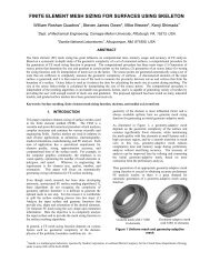
<strong>3A.2</strong><br />
<strong>Methods</strong> <strong>and</strong> <strong>Applications</strong> <strong>of</strong> <strong>Generalized</strong><br />
<strong>Sheet</strong> Insertion for Hexahedral Meshing<br />
Karl Merkley 1 , Corey Ernst 2 , Jason F. Shepherd 3 , <strong>and</strong> Michael J. Borden 4<br />
1 Computational Simulation S<strong>of</strong>tware, LLC., American Fork, UT<br />
karl@csims<strong>of</strong>t.com<br />
2 Elemental Technologies, Inc., American Fork, UT corey@elemtech.com<br />
3 S<strong>and</strong>ia National Laboratories, Albuquerque, NM jfsheph@s<strong>and</strong>ia.gov<br />
4 S<strong>and</strong>ia National Laboratories, Albuquerque, NM mborden@s<strong>and</strong>ia.gov<br />
Summary. This paper presents methods <strong>and</strong> applications <strong>of</strong> sheet insertion in a<br />
hexahedral mesh. A hexahedral sheet is dual to a layer <strong>of</strong> hexahedra in a hexahedral<br />
mesh. Because <strong>of</strong> symmetries within a hexahedral element, every hexahedral mesh<br />
can be viewed as a collection <strong>of</strong> these sheets. It is possible to insert new sheets into<br />
an existing mesh, <strong>and</strong> these new sheets can be used to define new mesh boundaries,<br />
refine the mesh, or in some cases can be used to improve quality in an existing mesh.<br />
<strong>Sheet</strong> insertion has a broad range <strong>of</strong> possible applications including mesh generation,<br />
boundary refinement, R-adaptivity <strong>and</strong> joining existing meshes. Examples <strong>of</strong> each<br />
<strong>of</strong> these applications are demonstrated.<br />
Key words: hexahedra, meshing, dual, boundary layers, refinement<br />
1 Introduction<br />
<strong>Sheet</strong> insertion is a technique for modifying the topology <strong>of</strong> a hexahedral mesh<br />
<strong>and</strong> introducing new elements which geometrically correlate with the shape <strong>of</strong><br />
the sheet. These topological changes <strong>and</strong> the new elements introduced by the<br />
insertion provide methods for defining, refining, <strong>and</strong> improving the quality <strong>of</strong><br />
a mesh. This paper will review several applications <strong>of</strong> sheet insertion including<br />
pillowing, dicing, refinement, grafting, <strong>and</strong> mesh cutting <strong>and</strong> show how these<br />
methods are related by the sheet insertion technique.<br />
Every hexahedral mesh is defined as a collection <strong>of</strong> hex sheets. A hexahedral<br />
sheet is dual to a layer <strong>of</strong> hexahedra <strong>and</strong> can be geometrically correlated<br />
to the shape <strong>of</strong> the hexahedral sheet. A sheet <strong>of</strong> hexahedra can be easily<br />
visualized by examining an equivalent structure in two dimensions. Given a<br />
quadrilateral mesh, a layer <strong>of</strong> quadrilaterals is found by starting at the center<br />
<strong>of</strong> a single quadrilateral <strong>and</strong> traversing through the opposite edge pairs <strong>of</strong><br />
connected quadrilaterals in both directions. The layer will always end by returning<br />
to the original quadrilateral or reaching the boundary <strong>of</strong> the mesh, as
234 Merkley, Ernst, Shepherd, Borden<br />
shown in figure 1. A continuous line drawn through this layer <strong>of</strong> quadrilaterals<br />
can be used visually to represent all <strong>of</strong> the quadrilaterals in the layer. This<br />
line segment is known as a chord, <strong>and</strong> is dual to the layer <strong>of</strong> quadrilateral<br />
elements.<br />
Fig. 1. Rows <strong>of</strong> quadrilaterals.<br />
This description can be extended to hexahedra in three-dimensions. A<br />
layer <strong>of</strong> hexahedra can be visualized as a single manifold surface. This surface<br />
is known as a ‘sheet’, where a sheet is dual to a layer <strong>of</strong> hexahedra. Each<br />
hexahedron can be defined as a parametric object with 3 sets <strong>of</strong> 4 edges, where<br />
all edges in a set are normal to the same parametric coordinate direction,<br />
either i, j, or k. Starting from any hexahedron, we can create a sheet <strong>of</strong><br />
hexahedra by first obtaining a set <strong>of</strong> edges in one <strong>of</strong> the three parametric<br />
directions. Next, we collect all neighboring hexahedra sharing these edges. For<br />
each neighboring hexahedron obtain the set <strong>of</strong> edges in the same parametric<br />
direction as the initial hexahedron. Using these edges, continue to propagate<br />
outwards, collecting neighboring hexahedra. When all adjacent hexahedra are<br />
collected in this manner, the result will be a layer <strong>of</strong> hexahedra that is manifold<br />
within the boundary <strong>of</strong> the mesh (that is the layer will either terminate at<br />
the boundary <strong>of</strong> the mesh, or will form a closed boundary within the mesh).<br />
This layer <strong>of</strong> hexahedra can be visualized as a single manifold surface, known<br />
as a sheet, where the sheet is dual to a layer <strong>of</strong> hexahedra (see figure 2).<br />
Introduction <strong>of</strong> new sheets in a hexahedral mesh modifies the topology <strong>of</strong><br />
the existing mesh <strong>and</strong> introduces new layers <strong>of</strong> elements within the mesh. As<br />
long as the sheets intersect according to a set <strong>of</strong> topological constraints for a<br />
hexeahedral mesh [1, 2], the resulting mesh with the new sheet will still be a<br />
hexahedral mesh. Using this principle, a hexahedral mesh may be modified by<br />
inserting new hex sheets in specific manners depending upon the application<br />
to realize new meshes, define new mesh boundaries, refine an existing mesh,<br />
or improve the quality <strong>of</strong> a hexahedral mesh.
<strong>3A.2</strong> <strong>Generalized</strong> <strong>Sheet</strong> Insertion 235<br />
Fig. 2. <strong>Sheet</strong>s <strong>of</strong> hexahedra.<br />
2 Motivation<br />
Hexahedral meshing has been an active research topic for many years [3].<br />
There have been a number <strong>of</strong> attempts at generalized meshing algorithms<br />
such as plastering [4], whisker-weaving [5, 6, 7] <strong>and</strong> unconstrained plastering<br />
[8]. While significant progress as been made <strong>and</strong> some <strong>of</strong> these algorithms<br />
show promise for specific geometric types, hex meshing is still considered an<br />
open problem [9].<br />
The most successful algorithms for hexahedral mesh generation are based<br />
on geometric primitives. For example, a mapping algorithm is based on a<br />
parametric cube [10]. Blocking algorithms wrap a geometry in a known hexahedral<br />
primitive [11, 12, 13, 14]. Submapping algorithms virtually decompose<br />
a geometry into cube-shaped primitives [15]. Sweeping algorithms are based<br />
on extrusions <strong>of</strong> 2D geometric shapes [16, 17, 18].<br />
<strong>Sheet</strong> insertion <strong>of</strong>fers techniques that can extend the capabilities <strong>of</strong> primitive<br />
based algorithms. Because sheet insertion provides methods for modifying<br />
hexahedral meshes, it can be considered as somewhat analogous to tetrahedral<br />
mesh modifications such as edge swapping. Tetrahedral mesh modification operations<br />
tend to be local <strong>and</strong> only affect the elements in the immediate area <strong>of</strong><br />
the change. However, due to the topological structure <strong>of</strong> hexahedral meshes,<br />
modification <strong>of</strong> a hexahedral mesh affects the mesh in a non-local manner.<br />
<strong>Sheet</strong> insertion quantifies the scope <strong>of</strong> the non-local changes <strong>and</strong> provides<br />
effective tools for hexahedral mesh modification.<br />
The remainder <strong>of</strong> this paper provides an overview <strong>of</strong> several algorithms<br />
utilizing sheet insertion. The scope <strong>of</strong> each algorithm is different, depending<br />
on the application for which the algorithm was initially intended. The<br />
common thread running through these algorithms is that they introduce new<br />
sheets into an existing hexahedral mesh. The new sheets are then utilized<br />
to affect changes to the original mesh including geometric boundary modification,<br />
refinement, quality improvement, <strong>and</strong> mesh adaptivity. We provide a<br />
survey <strong>of</strong> these sheet insertion algorithms, <strong>and</strong> then <strong>of</strong>fer several examples <strong>of</strong><br />
how sheet insertion can be utilized to generate hexahedral meshes in complex<br />
geometries, adaptively conform a mesh topology to specific supposed analytic
236 Merkley, Ernst, Shepherd, Borden<br />
Fig. 3. A basic pillowing operation starts with an initial mesh (A) from which a<br />
subset <strong>of</strong> elements is defined to create a shrink set. The shrink set is separated from<br />
the original mesh <strong>and</strong> ‘shrunk’ (B), <strong>and</strong> a new layer <strong>of</strong> elements (i.e., a dual sheet)<br />
is inserted (C) to fill the void left by the shrinking process.<br />
properties within a simulation, improve the mesh quality within an existing<br />
mesh, or control mesh sizing.<br />
3 <strong>Methods</strong><br />
This section provides an overview <strong>of</strong> hexahedral mesh modification methods<br />
that rely on sheet insertion, including pillowing, dicing, refinement, mesh cutting<br />
<strong>and</strong> grafting.<br />
3.1 Pillowing<br />
Pillowing is a method for inserting a single sheet into an existing hexahedral<br />
mesh. Initially proposed by Mitchell et al. [19], a pillowing operation provides<br />
a means for eliminating problematic mesh topology.<br />
The basic pillowing algorithm is as follows:<br />
1. Define a shrink set - Divide the existing mesh into two sets <strong>of</strong> elements: one<br />
set for each <strong>of</strong> the half-spaces defined by the sheet to be inserted. Choose<br />
one set as the shrink set. The set with the fewest number <strong>of</strong> elements is<br />
typically chosen as the shrink set.<br />
2. Shrink the shrink set - Create a gap region between the two element sets<br />
(see figure 3).<br />
3. Connect with a layer <strong>of</strong> elements - Create a fully-conformal mesh with<br />
the new sheet inserted between the original two element sets.<br />
It is <strong>of</strong>ten desirable to smooth the resulting mesh after the sheet insertion<br />
to obtain better nodal placement <strong>and</strong> higher quality elements. The speed <strong>of</strong>
<strong>3A.2</strong> <strong>Generalized</strong> <strong>Sheet</strong> Insertion 237<br />
the pillowing algorithm is largely dependent on the time needed to find the<br />
shrink set. The number <strong>of</strong> new hexahedra created will be equal to the number<br />
<strong>of</strong> quadrilaterals on the boundary <strong>of</strong> the shrink set.<br />
Pillowing is an operation for inserting a single sheet into an existing mesh.<br />
It is a useful multipurpose, foundational tool for operations on hexahedral<br />
meshes <strong>and</strong> is the basis for other mesh modification tools, including refinement,<br />
grafting, <strong>and</strong> mesh-cutting.<br />
3.2 Dicing<br />
The dicing algorithm [20] was created to efficiently generate large, refined<br />
meshes from existing coarse meshes by duplicating sheets within the coarse<br />
mesh. Each sheet is copied <strong>and</strong> placed in a parallel configuration to the sheet<br />
being copied. The basic method for dicing is as follows:<br />
1. Define the sheet to be diced - See sheet definition in introduction.<br />
2. Dice the edges - Split or dice the list <strong>of</strong> edges found in the previous step<br />
the specified number <strong>of</strong> times.<br />
3. Form the new sheets - Redefine the hexahedra based on the split edges.<br />
Utilizing the dicing method, the number <strong>of</strong> elements increases as the cube<br />
<strong>of</strong> the dicing value. For instance, if an existing mesh is diced four times (i.e.,<br />
each <strong>of</strong> the sheets in the existing mesh is split four times), the resulting mesh<br />
would have 64X as many elements as the original mesh. Because all search<br />
operations can be performed directly, the dicing algorithm can produce large<br />
meshes at very efficient speeds (see figure 4).<br />
3.3 Refinement<br />
The size <strong>of</strong> a hexahedral mesh is relative to the sheet density in the mesh.<br />
Increasing the element count within a region <strong>of</strong> the mesh can be accomplished<br />
Fig. 4. The original mesh (left) contains 1,805 hex elements before dicing. Each<br />
sheet in the original mesh is copied three times resulting in a mesh that is 3 3 larger,<br />
with 48,735 hex elements.
238 Merkley, Ernst, Shepherd, Borden<br />
by increasing the density <strong>of</strong> the sheets in the region. Refinement algorithms<br />
typically utilize predefined templates to increase the element density. These<br />
templates <strong>and</strong> the algorithms that insert them ensure manifold sheet structures<br />
within the mesh to maintain mesh validity [21, 22]. A basic refinement<br />
algorithm is constructed as follows:<br />
1. Define the region or elements to be refined - Replace the hexahedra in the<br />
refinement region with a predefined template <strong>of</strong> smaller elements.<br />
2. Cap the boundary <strong>of</strong> the refinement region to ensure conformity to the rest<br />
<strong>of</strong> the mesh. - Create a second set <strong>of</strong> templated elements which transition<br />
from the refinement template back to the original mesh size. Figure 5<br />
demonstrates this process.<br />
3.4 Mesh cutting<br />
The mesh-cutting [23] method is an effective approach for capturing geometric<br />
surfaces within an existing mesh topology. The mesh-cutting method utilizes<br />
the pillowing <strong>and</strong> dicing methods mentioned previously to insert two sheets<br />
which are geometrically similar to the surface to be captured. By utilizing two<br />
sheets, a layer <strong>of</strong> quadrilaterals results that approximates the desired surface<br />
where each <strong>of</strong> the new quadrilateral is shared between the hexes in the two<br />
new sheets. The mesh-cutting method entails the following steps:<br />
Fig. 5. Refinement <strong>of</strong> a hex mesh using refinement templates. Refinement region is<br />
shown as a dashed line.
<strong>3A.2</strong> <strong>Generalized</strong> <strong>Sheet</strong> Insertion 239<br />
1. Define the pillowing shrink set - Divide the existing mesh into two sets<br />
<strong>of</strong> elements. One <strong>of</strong> these element sets will be the shrink set, <strong>and</strong> a sheet<br />
(pillow) is inserted between the two sets <strong>of</strong> elements.<br />
2. Dice the new sheet - Split the newly inserted sheet into two sheets utilizing<br />
an approach similar to dicing.<br />
3. Move the shared quadrilaterals to the surface - Find all <strong>of</strong> the quadrilaterals<br />
that are shared by the hexes between the two sheets. These quadrilaterals<br />
become the mesh on the surface being cut (see figure 6).<br />
Because the quadrilaterals between the two new sheets approximate the<br />
surface, the mesh topology must be fine enough to capture the detail <strong>of</strong> the<br />
surface being inserted. Because the resulting quadrilaterals only approximate<br />
the inserted surface, if the resulting quadrilateral mesh is too coarse, the<br />
surface may not be approximated adequately.<br />
3.5 Grafting<br />
The term ‘grafting’ is derived from the process <strong>of</strong> grafting a branch from<br />
one tree into the stem, or trunk, <strong>of</strong> another tree. In meshing, the grafting<br />
method was developed to allow a branch mesh to be inserted into the linking<br />
surface <strong>of</strong> a previously hexahedrally swept volume [24]. The grafting method<br />
<strong>of</strong>fers a reasonably generalized approach to multiaxis sweeping. The method<br />
for creating a graft (i.e., capturing the geometric curve) can be outlined as<br />
follows (see also figure 7):<br />
1. Create a pillowing shrink set - The shrink set is defined as the set <strong>of</strong> hexes<br />
which have one quadrilateral on the surface <strong>and</strong> which are interior to the<br />
bounding curves <strong>of</strong> the graft.<br />
Fig. 6. Mesh cutting utilizes an existing mesh <strong>and</strong> inserts new sheets to capture a<br />
geometric surface (the existing mesh is shown in (A) where the spherical surface is<br />
the surface to be captured.) The resulting mesh after mesh cutting is shown in (B),<br />
with a close-up <strong>of</strong> the quadrilaterals on the captured surface being shown in (C).
240 Merkley, Ernst, Shepherd, Borden<br />
Fig. 7. A view <strong>of</strong> the hex sheets that were inserted into one <strong>of</strong> the trunk volumes<br />
by the grafting algorithm. The figure on the left highlights the sheets where they<br />
intersect the surface <strong>of</strong> the volume. The figure on the right shows the orientation <strong>of</strong><br />
the sheets in the interior <strong>of</strong> the mesh.<br />
2. Insert the pillow (sheet) -Inserting the second sheet to satisfy the hexahedral<br />
constraint for capturing the geometric curves used in the graft.<br />
At this point, there are <strong>of</strong>ten database adjustments needed to ensure that<br />
the new mesh entities are associated with the correct geometric entities.<br />
4 <strong>Applications</strong><br />
Because hexahedral sheet insertion operations are extremely flexible, there<br />
are numerous possible applications. This section demonstrates a few <strong>of</strong> these<br />
applications. The meshes in this section were developed using Cubit [25],<br />
developed at S<strong>and</strong>ia National Laboratories, SCIRun [26], developed at the<br />
University <strong>of</strong> Utah, or a combination <strong>of</strong> the two tools. The processes for<br />
completing these models are not yet fully automated, but there is ongoing<br />
development to make these processes robust <strong>and</strong> usable.<br />
4.1 R-Adaptivity<br />
<strong>Sheet</strong> insertion can be used to divide a model <strong>and</strong> refine the mesh in a given<br />
region. Figure 8 shows an R-adaptive mesh capturing a shock a wave. An<br />
initial sheet is placed that is aligned with the shock wave <strong>and</strong> mesh-cutting<br />
techniques are used to capture the shock wave. Additional sheets are then<br />
added to provide the required resolution around the shock wave.<br />
Adaptive smoothing operations can be utilized to control orthogonality<br />
<strong>and</strong> mesh spacing close to the adaptive region. The mesh after several operations<strong>of</strong>layersmoothingisshowninfigure9.
<strong>3A.2</strong> <strong>Generalized</strong> <strong>Sheet</strong> Insertion 241<br />
Fig. 8. <strong>Sheet</strong>s can be placed within a mesh to capture analytic features, such as<br />
shock waves. The original mesh is shown on the left. After several sheet insertion<br />
operations to place layers <strong>of</strong> elements roughly conforming to a supposed shock, the<br />
newly modified mesh is shown on the right. Mesh generated using Cubit.<br />
Fig. 9. Smoothing <strong>of</strong> R-adaptive region using Cubit<br />
4.2 Boundary Layers<br />
<strong>Sheet</strong> insertion techniques can be used in a similar manner to capture boundary<br />
layers as shown in airfoil mesh in figure 10. Inserted sheets can provide<br />
additional resolution at the boundary. The number <strong>of</strong> layers <strong>and</strong> the distribution<br />
<strong>of</strong> the sheets could be specified according to the requirements <strong>of</strong> the<br />
application.<br />
Additionally, new geometric features can be added by the sheet insertion<br />
process. For example, the geometry in figure 11 was split through the center
242 Merkley, Ernst, Shepherd, Borden<br />
<strong>of</strong> the airfoil. This model provides a mesh that is more closely aligned with<br />
streamlines through the entire model. Because varying applications may pose<br />
different requirements on the analysis model, the flexibility provided by the<br />
sheet insertion techniques can be very valuable.<br />
Fig. 10. <strong>Sheet</strong>s <strong>of</strong> hexahedra can be inserted to capture boundary layers. Mesh<br />
generated in Cubit.<br />
Fig. 11. <strong>Sheet</strong>s <strong>of</strong> hexahedra added to better resolve streamlines <strong>of</strong> model. Mesh<br />
generated in Cubit.<br />
4.3 Mesh Generation<br />
Hexahedral sheet insertion also provides techniques that can be used to generate<br />
complex meshes. The typical mesh-cutting technique involves embedding<br />
the desired geometry into an existing hexahedral mesh that envelopes the geometry.<br />
One or more sheets are then inserted into the mesh which capture the
<strong>3A.2</strong> <strong>Generalized</strong> <strong>Sheet</strong> Insertion 243<br />
missing, but desired, geometric features. Additional sheets may be inserted to<br />
improve the element quality at the boundary.<br />
Figure 12 shows an all hexahedral mesh <strong>of</strong> a human h<strong>and</strong> while <strong>and</strong> figure<br />
13 shows the internal detail <strong>of</strong> one finger <strong>of</strong> this model. This mesh was<br />
generated in SCIRun using a sheet insertion operation, similar to mesh cutting.<br />
Once the initial mesh was captured as desired, four additional layers <strong>of</strong><br />
hexahedra were added at the boundary (for a total <strong>of</strong> five boundary layers)<br />
that are oriented orthogonally to the surface. This was accomplished by dicing<br />
the original sheet used to capture the surface <strong>of</strong> the h<strong>and</strong>. The resulting<br />
mesh contains 379,429 hexahedra elements, <strong>and</strong> the mesh contains all positive<br />
Jacobian <strong>and</strong> well shaped hexahedra. Figure 14 shows the spread <strong>of</strong> scaled<br />
Jacobian element quality.<br />
Fig. 12. All hexahedral mesh <strong>of</strong> a human h<strong>and</strong> created by mesh cutting. The original<br />
triangle mesh <strong>of</strong> the h<strong>and</strong> that was utilized in controlling the placement <strong>of</strong> the<br />
hexahedral boundary layer was provided courtesy <strong>of</strong> INRIA by the AIM@SHAPE<br />
Shapes Repository http://shapes.aim-at-shape.net/index.php). Mesh generated in<br />
SCIRun.<br />
Biomedical applications are a source <strong>of</strong> very difficult modeling problems.<br />
Figure 15 shows a model <strong>of</strong> an all hexahedral mesh <strong>of</strong> a human skull <strong>and</strong><br />
cranial cavity. The meshes were formed by first creating a rectilinear mesh<br />
that was sized such that the bounding box was slightly larger than the skull.<br />
Triangular meshes <strong>of</strong> the skull <strong>and</strong> the cranial cavity were then inserted into
244 Merkley, Ernst, Shepherd, Borden<br />
Fig. 13. Cut-away view <strong>of</strong> one <strong>of</strong> the fingers for the all-hexahedral mesh <strong>of</strong> a human<br />
h<strong>and</strong> showing the internal structure <strong>of</strong> the mesh.<br />
Fig. 14. Distibution <strong>of</strong> element quality by the scaled Jacobian metric for the h<strong>and</strong><br />
model.
<strong>3A.2</strong> <strong>Generalized</strong> <strong>Sheet</strong> Insertion 245<br />
the rectilinear mesh to capture the surface data. The level <strong>of</strong> detail captured<br />
in this technique is proportional to the level <strong>of</strong> detail <strong>of</strong> the triangular surface<br />
mesh. Additional sheets where inserted at the surface to improve the quality<br />
<strong>of</strong> the mesh at the surface. Figure 16 shows a cut-away view <strong>of</strong> the mesh<br />
(accomplished again with a mesh-cutting operation) to give a view <strong>of</strong> the<br />
internal structure <strong>of</strong> the mesh. The mesh <strong>of</strong> the skull contains 77,775 elements<br />
consisting <strong>of</strong> well-shaped hexahedra with all positive Jacobian measures. The<br />
quality distribution for the elements <strong>of</strong> this mesh is shown in figure 17.<br />
Fig. 15. All hexahedral mesh <strong>of</strong> a human skull <strong>and</strong> cranial cavity. The original<br />
triangle mesh <strong>of</strong> the skull that was utilized in controlling the placement <strong>of</strong> the<br />
hexahedral boundary layer was provided courtesy <strong>of</strong> INRIA by the AIM@SHAPE<br />
Shapes Repository http://shapes.aim-at-shape.net/index.php). Mesh generated in<br />
SCIRun.<br />
4.4 Grafting<br />
The grafting algorithm [27] was developed to allow a volume to be imprinted<br />
<strong>and</strong> merged with another volume after the initial volume was meshed. The<br />
grafting algorithm locally modifies the initial mesh to conform to the geometry<br />
<strong>of</strong> the second, unmeshed volume. One application <strong>of</strong> this algorithm has been<br />
generating swept meshes for models with two independent sweep directions.<br />
For example, suppose an engineer is interested in analyzing the fluid flow<br />
through the valve housing shown in figure 18. The fluid region with the valve<br />
partially closed is shown in figure 19. Notice that there is an independent sweep<br />
direction corresponding to each pipe opening from the valve. To generate a
246 Merkley, Ernst, Shepherd, Borden<br />
Fig. 16. Cutaway view showing the interior structure <strong>of</strong> the all hexahedral mesh <strong>of</strong><br />
a human skull <strong>and</strong> cranial cavity. Cutaway created in Cubit.<br />
Fig. 17. Distribution <strong>of</strong> element quality by the scaled Jacobian metric for the skull<br />
model. The black bars represent the quality <strong>of</strong> the interior cranial mesh, while the<br />
white bars are representative <strong>of</strong> the skull bone.
<strong>3A.2</strong> <strong>Generalized</strong> <strong>Sheet</strong> Insertion 247<br />
mesh <strong>of</strong> this region with grafting, one would first mesh the two volumes that<br />
aresplitbythevalveplateasshowninfigure19.Theremainingunmeshed<br />
volume can then be grafted onto the meshed volumes as shown in figure 20.<br />
The grafting operation introduces a minimal, local change to the mesh as<br />
showninfigure7.<br />
Fig. 18. A valve housing<br />
Fig. 19. The fluid region <strong>of</strong> the valve housing in figure 18 with the valve partially<br />
closed (left) <strong>and</strong> the initial, pre-grafting swept mesh (right)
248 Merkley, Ernst, Shepherd, Borden<br />
Fig. 20. The area <strong>of</strong> the mesh that has been modified by grafting. The figure on<br />
the left shows the imprint <strong>of</strong> the branch volume onto the trunk volumes. The figure<br />
on the right shows the final mesh on the branch. Mesh created in Cubit.<br />
5 Conclusion<br />
<strong>Generalized</strong> hexahedral sheet insertion is an effective technique for modifying<br />
hexahedral meshes, including defining new mesh boundaries, refining the<br />
mesh, <strong>and</strong> improving the quality <strong>of</strong> an existing mesh. The technique is very<br />
flexible <strong>and</strong> can be applied in a variety <strong>of</strong> methods to modify a mesh, including<br />
R-adaptivity, refinement, boundary layer insertion, mesh generation, <strong>and</strong><br />
mesh improvement.<br />
The examples presented here have shown that sheet insertion can greatly<br />
decrease the effort required to construct a high quality mesh on difficult models.<br />
In particular, sheet insertion as a mesh generation tool for biomedical<br />
models shows great promise. This method could easily be extended into other<br />
promising areas. Geotechnical analysis requires models similar to those found<br />
in biomedical applications—they are <strong>of</strong>ten irregularly shaped <strong>and</strong> possess little<br />
or no topology that can be used to define the structure needed by traditional<br />
hexahedral meshing schemes. Additionally, sheet insertion methods, like mesh<br />
cutting <strong>and</strong> grafting, can also be utilized to dramatically reduce the level <strong>of</strong> geometric<br />
decomposition that is traditionally required to generate a hexahedral<br />
mesh on complex geometries.<br />
Acknowledgment<br />
S<strong>and</strong>ia is a multiprogram laboratory operated by S<strong>and</strong>ia Corporation, a Lockheed<br />
Martin Company, for the United States Department <strong>of</strong> Energy’s National<br />
Nuclear Security Administration under contract DE-AC04-94AL85000.
<strong>3A.2</strong> <strong>Generalized</strong> <strong>Sheet</strong> Insertion 249<br />
References<br />
1. Scott A. Mitchell. A characterization <strong>of</strong> the quadrilateral meshes <strong>of</strong> a surface<br />
which admit a compatible hexahedral mesh <strong>of</strong> the enclosed volumes. In 13th<br />
Annual Symposium on Theoretical Aspects <strong>of</strong> Computer Science, volume Lecture<br />
Notes in Computer Science: 1046, pages 465–476, 1996.<br />
2. Jason F. Shepherd. Topologic <strong>and</strong> Geometric Constraint-Based Hexahedral Mesh<br />
Generation. Published Doctoral Dissertation, University <strong>of</strong> Utah, May 2007.<br />
3. Steven J. Owen. A survey <strong>of</strong> unstructured mesh generation technology. http:<br />
//www.<strong>and</strong>rew.cmu.edu/user/sowen/survey/index.html, September 1998.<br />
4. Ted D. Blacker <strong>and</strong> Ray J. Meyers. Seams <strong>and</strong> wedges in plastering: A 3D<br />
hexahedral mesh generation algorithm. Engineering With Computers, 2(9):83–<br />
93, 1993.<br />
5. Timothy J. Tautges, Ted D. Blacker, <strong>and</strong> Scott A. Mitchell. Whisker weaving:<br />
A connectivity-based method for constructing all-hexahedral finite element<br />
meshes. International Journal for Numerical <strong>Methods</strong> in Engineering, 39:3327–<br />
3349, 1996.<br />
6. Matthias Muller-Hannemann. Hexahedral mesh generation by successive dual<br />
cycle elimination. In Proceedings, 7th International Meshing Roundtable, pages<br />
365–378. S<strong>and</strong>ia National Laboratories, October 1998.<br />
7. Nestor A. Calvo <strong>and</strong> Sergio R. Idelsohn. All-hexahedral element meshing: Generation<br />
<strong>of</strong> the dual mesh by recurrent subdivision. Computer <strong>Methods</strong> in Applied<br />
Mechanics <strong>and</strong> Engineering, 182:371–378, 2000.<br />
8. Matthew L. Staten, Steven J. Owen, <strong>and</strong> Ted D. Blacker. Unconstrained paving<br />
<strong>and</strong> plastering: A new idea for all hexahedral mesh generation. In Proceedings,<br />
14th International Meshing Roundtable, pages 399–416. S<strong>and</strong>ia National<br />
Laboratories, September 2005.<br />
9. Erik D. Demain, Joseph S.B. Mitchell, <strong>and</strong> Joseph O’Rourke. http://maven.<br />
smith.edu/~orourke/TOPP/P27.html#Problem.27, 2006. The open problems<br />
project - problem 27: Hexahedral meshing.<br />
10. W. A. Cook <strong>and</strong> W. R. Oakes. Mapping methods for generating threedimensional<br />
meshes. Computers In Mechanical Engineering, CIME Research<br />
Supplement:67–72, August 1982.<br />
11. John F. Dannenh<strong>of</strong>fer(III). A block-structuring technique for general geometries.<br />
In 29th Aerospace Sciences Meeting <strong>and</strong> Exhibit, volume AIAA-91-0145,<br />
January 1991.<br />
12. XYZ Scientific <strong>Applications</strong>, Inc. Truegrid: High quality hexahedral grid <strong>and</strong><br />
mesh generation for fluids <strong>and</strong> structures. http://www.truegrid.com, October<br />
2006.<br />
13. Pointwise. Gridgen - reliable CFD meshing. http://www.pointwise.com/<br />
gridgen, October 2006.<br />
14. ANSYS. ANSYS ICEM CFD, http://www.ansys.com/products/icemcfd.asp,<br />
October 2006.<br />
15. David R. White, Mingwu Lai, Steven E. Benzley, <strong>and</strong> Gregory D. Sjaardema.<br />
Automated hexahedral mesh generation by virtual decomposition. In Proceedings,<br />
4th International Meshing Roundtable, pages 165–176. S<strong>and</strong>ia National<br />
Laboratories, October 1995.<br />
16. Patrick Knupp. Next-generation sweep tool: A method for generating all-hex<br />
meshes on two-<strong>and</strong>-one-half dimensional geometries. In Proceedings, 7th In-
250 Merkley, Ernst, Shepherd, Borden<br />
ternational Meshing Roundtable, pages 505–513. S<strong>and</strong>ia National Laboratories,<br />
October 1998.<br />
17. Xevi Roca, Josep Sarrate, <strong>and</strong> Antonio Huerta. Surface mesh projection for<br />
hexahedral mesh generation by sweeping. In Proceedings, 13th International<br />
Meshing Roundtable, volume SAND 2004-3765C, pages 169–180. S<strong>and</strong>ia National<br />
Laboratories, September 2004.<br />
18. Mingwu Lai, Steven E. Benzley, <strong>and</strong> David R. White. Automated hexahedral<br />
mesh generation by generalized multiple source to multiple target sweeping.<br />
International Journal for Numerical <strong>Methods</strong> in Engineering, 49(1):261–275,<br />
September 2000.<br />
19. Scott A. Mitchell <strong>and</strong> Timothy J. Tautges. Pillowing doublets: Refining a<br />
mesh to ensure that faces share at most one edge. In Proceedings, 4th International<br />
Meshing Roundtable, pages 231–240. S<strong>and</strong>ia National Laboratories,<br />
October 1995.<br />
20. Darryl J. Mel<strong>and</strong>er, Timothy J. Tautges, <strong>and</strong> Steven E. Benzley. Generation<br />
<strong>of</strong> multi-million element meshes for solid model-based geometries: The dicer<br />
algorithm. AMD - Trends in Unstructured Mesh Generation, 220:131–135, July<br />
1997.<br />
21. Ko-Foa Tchon, Julien Dompierre, <strong>and</strong> Ricardo Camarero. Conformal refinement<br />
<strong>of</strong> all-quadrilateral <strong>and</strong> all-hexahedral meshes according to an anisotropic<br />
metric. In Proceedings, 11th International Meshing Roundtable, pages 231–242.<br />
S<strong>and</strong>ia National Laboratories, September 2002.<br />
22. Nathan Harris, Steven E. Benzley, <strong>and</strong> Steven J. Owen. Conformal refinement<br />
<strong>of</strong> all-hexahedral meshes based on multiple twist plane insertion. In Proceedings,<br />
13th International Meshing Roundtable, pages 157–168. S<strong>and</strong>ia National<br />
Laboratories, September 2004.<br />
23. Michael J. Borden, Jason F. Shepherd, <strong>and</strong> Steven E. Benzley. Mesh cutting:<br />
Fitting simple all-hexahedral meshes to complex geometries. In Proceedings, 8th<br />
International Society <strong>of</strong> Grid Generation Conference, 2002.<br />
24. Steven R. Jankovich, Steven E. Benzley, Jason F. Shepherd, <strong>and</strong> Scott A.<br />
Mitchell. The graft tool: An all-hexahedral transition algorithm for creating<br />
multi-directional swept volume mesh. In Proceedings, 8th International Meshing<br />
Roundtable, pages 387–392. S<strong>and</strong>ia National Laboratories, October 1999.<br />
25. S<strong>and</strong>ia National Laboratories. The CUBIT Geometry <strong>and</strong> Mesh Generation<br />
Toolkit. http://cubit.s<strong>and</strong>ia.gov, 2007.<br />
26. Scientific Computing <strong>and</strong> Imaging Institute (SCI). SCIRun: A Scientific<br />
Computing Problem Solving Environment. http://s<strong>of</strong>tware.sci.utah.edu/<br />
scirun.html, 2002.<br />
27. S.R. Jankovich, S.E. Benzley, J.F. Shepherd, <strong>and</strong> S.A. Mithcell. The graft tool:<br />
an all-hexahedral transition algorithm for creating a mult-directional swep t<br />
volume mesh. In Proceedings, 8 th International Meshing Roundtable ‘99, pages<br />
387–392. S<strong>and</strong>ia National Laboratories, 1999.