کاتالوگ
کاتالوگ
کاتالوگ

Create successful ePaper yourself
Turn your PDF publications into a flip-book with our unique Google optimized e-Paper software.
2 راهکارهای مدیریت روشنایی | <strong>کاتالوگ</strong> محصوالت و سیستمها<br />
دفتر مرکزی لگراند در ایران<br />
شرکت صنایع الکتریکی البرز<br />
تهران، خیابان مطهری، خیابان کوه نور، خیابان<br />
هفتم، شماره 8 کدپستی: 1587684511<br />
: (+98 21) 8850 48 03 - 4<br />
Fax : (+98 21) 8873 45 67<br />
www.legrand.ir<br />
EXB09049
راهکارهای مدیریت روشنایی<br />
<strong>کاتالوگ</strong> محصوالت و سیستمها<br />
3 راهکارهای مدیریت روشنایی | <strong>کاتالوگ</strong> محصوالت و سیستمها<br />
مبارزه با اتالف انرژی
انرژی<br />
اتالف با مبازره سیستمها<br />
و محصوالت <strong>کاتالوگ</strong> | روشنایی مدیریت راهکارهای 2 فهرست<br />
3 ........................................................................ص ما چشمانداز 4<br />
دلیل؟....................................ص چه به روشنایی، مدیریت اجرای 6<br />
ص ........................... روشنایی مدیریت اجرای به مربوط الزامات 10<br />
ص ....................................... روشنایی مدیریت اجرای نحوهی 12<br />
.........................ص روشنایی مدیریت سیستمهای و محصوالت 26<br />
..................................................................ص مربوطه خدمات 28<br />
ص .............................................................. <strong>کاتالوگ</strong> صفحات 45<br />
ص ........................................................................... واژهنامه
ما<br />
چشمانداز کارآمدتر<br />
انرژی، مصرف نظر از را ساختمانها که است خدماتی و محصوالت ارائهی لگراند در ما چشمانداز سازند.<br />
هستیم.<br />
انرژی« اتالف با مبارزه « به متعهد ما و بوده اطمینان قابل سیستمها این میکنند. تضمین را شما حضور مکان و زمان در کافی نور وجود انرژی، کارآمد مصرف با روشنایی مدیریت سیستمهای هستند.<br />
زیست محیط حافظ و پایدار دارند، مطابقت مقررات با و میکاهند هزینهها از میکنند، تأمین را امنیت و ایمنی است، ساده آنها از استفاده سازد.<br />
مطمئن زیست، محیط حفظ به کمک نیز و انرژی صرفهجویی در را شما تا میدهد پیشنهاد را آنها به مربوط خدمات و ارائه را راهکار نوع دو لگراند سوئیچی<br />
حسگرهای سیستمها<br />
و محصوالت <strong>کاتالوگ</strong> | روشنایی مدیریت راهکارهای BUS | SCS<br />
سيستم 3
اجرای مدیریت روشنایی، به چه دلیل؟<br />
روشنایی یکی از مهمترین موارد مصرف انرژی در<br />
ساختمانهای تجاری است.<br />
20 درصد از کل انرژی ورودی در یک ساختمان تجاری را مصارف روشنایی تشکیل می دهد.<br />
روشنایی، در میان مصارف مختلف ساختمانهای تجاری، با<br />
40 درصد از کل انرژی مصرفی، جایگاه نخست را دارد.<br />
4 راهکارهای مدیریت روشنایی | <strong>کاتالوگ</strong> محصوالت و سیستمها<br />
* توزیع مصرف نهایی انرژی به شدت به فعالیت ساختمان و مناطق مختلف جغرافیایی و اقلیمی بستگی دارد.<br />
)منبع: ادارهی اطالعات انرژی، ایاالت متحده آمریکا(
به<br />
را ساختمان یک هزینههای و انرژی مصرف میزان باالترین مطبوع، تهویهی و گرمایش کنار در روشنایی، شکلی<br />
به میتوان را عمده هزینههای این روشنایی، مدیریت سیستم از استفاده با میدهند. اختصاص خود نمود.<br />
مدیریت مؤثرتر میگذارند،<br />
اجرا به را آن روشنایی، مدیریت گستردهی منافع از آگاهی با که سازمانهایی تعداد به ساله، هر میشود:<br />
افزوده انرژی<br />
مصرف در صرفهجویی موارد روشنایی<br />
مدیریت است. انرژی مصرف در صرفهجویی امر، این مزیت اولین احتماالً هزینههای<br />
که شود انرژی مصرف در صرفهجویی 30درصد از بیش به منجر میتواند میدهد)1(.<br />
کاهش بیشتر یا 10درصد میزان به را ساختمان راهبری هوشمندانهتر<br />
نحوی به چراغها که شکلی به روشنایی، خودکار مدیریت از استفاده با مناسب،<br />
و دقیق کامالً زمانی در مناسب، مکان در روشنایی مناسب سطح کنند: کار کرد.<br />
جلوگیری انرژی اتالف از میتوان اقتصادی<br />
صرفهجویی موارد صرفهجویی<br />
باعث آورده، پایین را راهبری هزینههای روشنایی، از استفاده کاهش میکند.<br />
کمک )GHG( گلخانهای گازهای انتشار کاهش به و میشود ها هزينه در المپ،<br />
تعویض مطبوع، تهویهی هزینههای کاهش در ریشه صرفهجویی، موارد سایر دارند.<br />
مصرف اوج ساعات در انرژی تقاضای کاهش و نگهداری + دستی حسگر سیستم )با EN 15193 استاندارد مبنای بر صرفهجویی 55درصد تا )2(<br />
روز( نور حسگر + دستی کلید مقررات<br />
با مطابقت انرژی<br />
مصرف الزامات – ساختمان در انرژی مصرف )عملکرد 15193 اروپایی استاندارد است.<br />
روشنایی بهینه مصرف سیستمهای تعریف برای اصلی استانداردی ساختمان( در میآورد.<br />
فراهم جهان سراسر در ساختمان مقررات بیشتر برای را پايه استاندارد این صرفهجویی<br />
محاسبات تمامی برای مبنایی عنوان به را استاندارد این لگراند گروه خصوص<br />
در را مشترک مفهوم بزرگترین تا نموده، انتخاب خود انرژی مصرف در اطمینان<br />
قابل نسبتهایی و آورد هم گرد جا یک در انرژي، بهينه مصرف سیستمهای دهد.<br />
ارائه را انرژی مصرف در صرفهجویی معتبر و سیستمها<br />
و محصوالت <strong>کاتالوگ</strong> | روشنایی مدیریت راهکارهای 5 پويا<br />
ساختمان رویهی LEED،<br />
BREEAM، )مثل: سبز ساختمان پروژهای در میتوان را روشنایی مدیریت کارآمدی<br />
راهکارهای همانند داد، قرار استفاده مورد غیره( و HQE، GREEN STAR شوند.<br />
ساکنان رفاه افزایش باعث میتوانند نیز آن که انرژی مصرف آمریکا<br />
انرژی، اطالعات ادارهی منبع: )1( است.<br />
دستیابی قابل )فعالیت( اتاق نوع و ساختمان نوع به بسته و حسگرها کمک به که صرفهجویی، از سطحی )2(
الزامات مربوط به اجرای مدیریت روشنایی<br />
مفهوم « سبز » صرفاً مفهومی مشترک است<br />
رویه های ساختمان پویا به سرعت در حال جذب پذیرش عمومی است<br />
6 راهکارهای مدیریت روشنایی | <strong>کاتالوگ</strong> محصوالت و سیستمها
در تمامی کشورهای توسعه یافته و نیز در تعدادی از کشورهای در حال توسعه، دولتها در حال تنظیم<br />
مقررات و استانداردهایی برای بهینهسازی عملکرد مصرف انرژی در ساختمانها هستند.<br />
شرایط الزامی و برنامههای داوطلبانه در حال افزایشند. این موارد دارای زمینهها و سطوح متفاوتی از<br />
الزامات هستند، ولی هدفی واحد را دنبال میکنند: بهینهسازی کارآمدی مصرف انرژی در ساختمانها.<br />
7<br />
رویکرد گروه:<br />
گروه لگراند یکی از اعضای فعال سازمانهای پرشماری است که در زمینهی کارآمدی صنعتی<br />
و مصرف انرژی فعالیت دارند.<br />
لگراند، با درک ضرورت حفظ محیط زیست و نگهداری منابع، تالش میکند تا روشهایی<br />
سبزتر اتخاذ نماید و تعهد خود به محیط زیست را به برنامههای راهبردی و فرایندهای<br />
تصمیمسازی مبدل سازد.<br />
راهکارهای مدیریت روشنایی | <strong>کاتالوگ</strong> محصوالت و سیستمها
روشنایی<br />
مدیریت اجرای برای الزم شرایط الزامی<br />
شرایط سیستمها<br />
و محصوالت <strong>کاتالوگ</strong> | روشنایی مدیریت راهکارهای میدهند<br />
ترویج را رویه بهترین که دارند وجود انرژی( غیرالزامی )استانداردهای استانداردهایی میروند.<br />
کار به آتی مقررات برای دستورالعملی عنوان به اغلب و انرژی<br />
مصرف در صرفهجویی استانداردهای مصرف<br />
صرفهجویی خصوص در را دستورالعملهایی نیز استانداردها از برخی اروپایی<br />
استاندارد مثال، عنوان به میدهند. ارائه خاص تأسیسات در انرژی سیستمهای<br />
انرژی مصرف عملکرد برای است دستورالعملی EN 15193 عملکرد<br />
اثبات برای مبنایی عنوان به را استاندارد این لگراند، روشنایی. است.<br />
نموده انتخاب خود روشنایی راهکارهای انرژی مصرف برای<br />
آن محاسباتی روش که شده، شناخته کامالً است استانداردی این ساختمان<br />
نوع منصوبه، راهکار نوع اساس بر انرژی، مصرف در صرفهجویی است.<br />
اتاق نوع و هک میرساند یاری لگراند به که است شناختهشدهای مرجع استاندارد، این باشد.<br />
داشته صحیحی جهتگیری انرژی، مصرف در صرفهجویی بازار در انرژی<br />
اتالف با مبارزه اتالف<br />
از خودکار، کنترلهای سایر و روشنایی مدیریت سیستم نصب با مطابق<br />
صرفاً ساختمان، در انرژی مصرف میزان و میشود جلوگیری انرژی بود.<br />
خواهد مصرف مناسب زمان در هم آن و واقعی، نیاز با واقعی<br />
موارد خصوص در شفاف، و جامع اطالعاتی که است متعهد لگراند خود<br />
مشتریان به را خویش، روشنایی مدیریت راهکارهای در صرفهجویی دهد:<br />
ارائه گلخانهای<br />
گازهای انتشار از جلوگیری + انرژی مصرف در صرفهجویی .)GHG(<br />
بیابید.<br />
رویهها بهترین زمینهی در ما كاتالوگ در را اطالعات این 8<br />
)1(<br />
انرژی در صرفهجویی سال<br />
در یورو 333 )2(<br />
گلخانهای گازهای انتشار از ممانعت میزان سال<br />
در CO2 کیلوگرم 751 معادل مساحت<br />
به انتظار سالن برای لگراند روشنایی مدیریت راهکار حضور<br />
بر مبتنی اتوماتیک کنترل مبنای: بر مربع، متر 220 روز<br />
کنترل + اشخاص EN 15 193<br />
استاندارد با مطابق )1( ،)CO<br />
2 ( دیاکسیدکربن ازون، آب، بخار شامل گلخانهای گازهای )2( .)N 2<br />
O( نیتروژن اکسید و ،) CH4 ( متان میشوند.<br />
محاسبه CO 2 معادل واحدهای حسب بر موارد این سوئیچی<br />
حسگر دستورالعمل از مثالی پارتیشنبندی<br />
بزرگ دفتری محیط - شده<br />
هر<br />
در کیلومتر، 100 در لیتر 4/5 مصرف میانگین با خودرویی توجه: 0/118<br />
یعنی میکند، منتشر CO 2 گاز کیلوگرم 11/8 کیلومتر، 100 کیلومتر.<br />
در CO 2 گرم
برنامههای داوطلبانه<br />
9 راهکارهای مدیریت روشنایی | <strong>کاتالوگ</strong> محصوالت و سیستمها<br />
رویکرد ما به ساختمان، در حال سوق به سمت راهی پایدارتر برای طراحی، احداث و بازسازی<br />
ساختمانها است.<br />
ساختمان سبز، رویکردی خاص به ساختمان است، که تأثیرات کلی ساختمان<br />
بر محیط زیست و نیز سالمت و رفاه ساکنین آن را مد نظر قرار میدهد.<br />
برنامههای ساختمان سبز<br />
ابتکارات مختلفی در خصوص ساختمان سبز در سراسر جهان در حال ظهور<br />
و بروز است، که چهارچوبهای محلی الزم را برای ایجاد ساختمانهای<br />
سبز فراهم میآورند.<br />
این برنامههای ساختمان سبز، برنامههایی داوطلبانه و توافقی هستند که<br />
دستورالعمل ساخت و ساز در راستای معیارهای پایدار را فراهم میآورند.<br />
این برنامهها، عموماً دارای ابزار سنجش مربوط به خود هستند، که به کمک<br />
آن عملکرد زیستمحیطی ساختمان را ارزیابی و انطباق آن را با استاندارد،<br />
تأیید نماید.<br />
گواهینامهی ساختمان سبز به پروژههای مختلف ساختمان پويا اعطاء و به<br />
آنها اعتبار میبخشد. عمدهترین برنامههای ساختمان سبز شامل LEED،<br />
،BREEAM، HQE و GREEN STAR هستند.
نحوهی اجرای مدیریت روشنایی<br />
راهبردهای مدیریت روشنایی<br />
راهکارهای مدیریت روشنایی | <strong>کاتالوگ</strong> محصوالت و سیستمها<br />
منظور از راهبردهای مدیریت روشنایی، روشی اساسی است که برای کنترل سیستمهای روشنایی<br />
به کار میرود. این روش، شامل عملیات خودکار روشنایی است، با در نظر گرفتن نیازهای افراد<br />
ساکن در فضای مربوطه.<br />
كنترل مبتني بر حضور افراد )اتوماتيك(<br />
روشن و خاموش شدن چراغها، پاسخی است به حضور<br />
اشخاص در محیط مورد نظر. این امر به فواصل زمانی<br />
یا زمانبندی مشخصی وابسته نیست، بلکه به موارد<br />
استفاده از محیط تحت کنترل پاسخ میدهد.<br />
كنترل مبتني بر عدم حضور افراد ( دستي(<br />
روشن و خاموش شدن چراغها، پاسخی است به خالی<br />
بودن محیط. این امر به فواصل زمانی یا زمانبندی<br />
مشخصی وابسته نیست، بلکه به موارد استفاده از محیط<br />
تحت کنترل پاسخ میدهد.<br />
کنترل زمانبندی شده<br />
روشنایی، بر اساس جداول زمانی مدیریت میشود، که<br />
مبنای آن باز یا اشغال بودن؛ و یا بسته یا خالی بودن<br />
ساختمان از افراد است.<br />
کنترل دیمری<br />
تنظیم میزان روشنایی برای دستیابی به تبدیالت یا<br />
ترازهای روشنایی متناسب با فعالیت های ساکنین<br />
کنترل سطح روشنایی<br />
راهبرد عبارت است از تنظیم سطح خروجی روشنایی از چند طریق به منظور<br />
دستیابی به اهدافی مشخص. انواع اصلی کنترل سطح روشنایی عبارتند از:<br />
استفاده از روشنی روز )نقطهی تنظیم روشنی روز(<br />
در قسمتهایی از داخل ساختمانها که مقدار قابل توجهی از<br />
نور روز را دریافت میکنند، به کمک این راهبرد، از این نور<br />
استفاده میشود تا کاربرد نور مصنوعی، تکمیل یا حذف شود.<br />
تنظیم کردن )نمایهی روشنایی(<br />
در این رویکرد با تنظیم سطح روشنایی، به سطوح مختلفی<br />
از روشنایی دست خواهیم یافت، که برای فعالیتهای مختلف<br />
ساکنین، مناسب باشد. به عنوان مثال، کسی که مشغول رسم<br />
نقشه یا مطالعه است، نسبت به کسی که سرگرم چیدن کاال<br />
در قفسهها است، به سطح باالتری از نور نیاز دارد.<br />
حفظ لومن )فلوی روشنایی(<br />
تمرکز این راهبرد، بر حفظ سطح معینی از شدت روشنایی در<br />
کل طول عمر المپهای سیستم روشنایی است. این راهبرد،<br />
برای انجام این عمل، در آغاز دورهی کاری، سطح روشنایی<br />
اولیه را کاهش میدهد، و با باال رفتن عمر المپها، سطح<br />
روشنایی را به تدریج افزایش میدهد.<br />
10
روشنایی<br />
مدیریت فناوریهای مورد<br />
خاص راهبردی اجرای جهت عمالً که است دستگاهی روشنایی، مدیریت فناوریهای از منظور دیمرها،<br />
)مثل: میشود استفاده آن از دستگاه نمودن عمل برای که روشی نیز و میگیرد، قرار استفاده دوگانه(.<br />
یا اولتراسونیک قرمز، مادون فناوریهای دارای حسگرهای و زمانسنجها حسگرها<br />
و استفاده افراد حضور تشخیص برای فناوریها از مجموعهی از حسگرها میکنند.<br />
ارسال قسمت روشنایی به را مناسب سیگنالهای )PIR(<br />
قرمز مادون فناوری مثل<br />
قرمز، مادون انرژی منابع به واکنش طریق از قرمز، مادون فناوری میکند.<br />
آشکار را اشخاص حضور حرکت، حال در انسان بدن آنها،<br />
پسزمینهی و انرژی منبعهای این بین تفاوت تشخیص با حسگر چراغ<br />
کردن روشن برای الزم سیگنال ارسال و فرد تشخیص به قادر مستقیمی<br />
دید داشتن مستلزم PIR حسگرهای مؤثر کارکرد است. دربربگیرد.<br />
کامالً را پوشش تحت محدودهی که است اولتراسونیک<br />
فناوری حضور<br />
تشخیص برای داپلر سیگنالدهی از حسگرها از نوع این خود<br />
از اولتراسونیک صوتی امواج حسگر، میکنند. استفاده افراد پوشش،<br />
تحت فضای در موجود اشیاء به برخورد با که میکند منتشر را<br />
امواج برگشت زمانی فاصلهی حسگر آنگاه میشوند. داده بازگشت امواج<br />
باشد، داشته وجود محدوده در حرکتی هرگاه میکند. محاسبه به<br />
که داشت، خواهند متفاوتی بسامدهای حسگر، به بازگشتی صوتی میشود.<br />
منجر افراد حضور تشخیص مستقیم<br />
دید امکان حسگر که است مطلوب کاربردهایی برای فناوری این است.<br />
پایین بسیار فعالیت سطح که مواردی در یا باشد، نداشته را دوگانه<br />
فناوری معموالً<br />
میکنند، استفاده PIR+US فناوریهای از که حسگرهایی عموماً<br />
میشوند. نامیده مرکب دستگاههای یا دوگانه« »فناوری دارای زمانی<br />
کلیدهای که<br />
میکنند، استفاده اولتراسونیک و PIR فناوریهای از تجهیزات این فناوری<br />
هردو توسط افراد حضور که میشوند روشن موقعی چراغها آن، در مذکور<br />
فناوری دو از یکی حداقل که مادامی تا و باشد، شده داده تشخیص ماند.<br />
خواهند باقی روشن دهد، تشخیص همچنان را افراد حضور روز<br />
روشنایی تنظیم نقطهی از<br />
طبیعی روشنایی سطوح که هنگامی در نور، سطح مشخصهی میدارد.<br />
نگه خاموش را چراغها رود، فراتر ازپیشتنظیمشده، سطح حسگرهای<br />
تمامی نمود. لغو یا و داد تغییر میتوان را تنظیمات این پیشفرض،<br />
صورت به کارکرد این هستند. مشخصه این دارای لگراند است.<br />
فعال روشن<br />
یا خاموش را چراغها معین، وقفهای از پس مکانیکی، یا الکترونیکی دستگاههای این دورههای<br />
از معموالً که داد، تغییر ساکنین نیاز طبق میتوان را زمانی وقفهی این میکنند. متغیرند.<br />
ساعت 12 بلندی به زمانی فواصل تا دقیقه، 5 مثل کوتاهی زمانی کلیدهای<br />
جایگزین اضافی، سیمکشی به نیاز بدون میتوان، را کلیدها این موارد، اغلب در نمود.<br />
قدیمی سادهی برای<br />
بار هر و مکرر، طور به که هستند قسمتهایی زمانی، کلیدهای این عملی کاربردهای قفسههای<br />
و انباریها، یا تاسيسات اتاقهای مثل میگیرند، قرار استفاده مورد کوتاه، مدتی کتاب.<br />
نگهداری نور<br />
تضعیف کنترلهای را<br />
دوری راه از کنترل انواع میتوانند کاری، محیطهای شخصی کنترل جهت کاربران، کند.<br />
تنظیم را روشنایی مقدار یا خاموش روشن، را چراغها که کنند، انتخاب زیرا<br />
است، مفید وظایف، اساس بر تنظیم برای ویژه به کنترل، انواع این از استفاده خویش<br />
کاری وظایف با را خود نیاز مورد روشنایی سطح میتواند کاربران از یک هر دهد.<br />
تطبیق سیستمها<br />
و محصوالت <strong>کاتالوگ</strong> | روشنایی مدیریت راهکارهای 11
مدیریت روشنایی محصوالت و سیستمها<br />
در هر پروژهی مدیریت روشنایی شما خواستار بهرهگیری از<br />
مناسبترین محصوالت هستید.<br />
12 راهکارهای مدیریت روشنایی | <strong>کاتالوگ</strong> محصوالت و سیستمها
از آنجایی که بهتر است راهبرد کنترلی را بر اساس نوع محیط انتخاب نمود، در بیشتر پروژهها<br />
استفاده از چندین راهکار ضرورت مییابد، به نحوی که صرفهجویی در انرژی و رضایتمندی<br />
ساکنین به طور کامل تأمین گردد.<br />
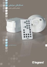
حسگرهای سوئیچی<br />
13<br />
راهکار کامل مدیریت روشنایی<br />
این راهکار برای مدیریت یک یا چند محیط، مطلوب است.<br />
راهکار مذکور شامل حسگرهای سوئیچی است که با ولتاژ<br />
240-100 متناوب کار میکنند. این حسگرهای سوئیچی<br />
در انواع راهبردهای مدیریت روشنایی حالت اشغالی و<br />
حالت خالی بودن موجود هستند و از فناوریهای ،PIR<br />
اولتراسونیک و دوگانه استفاده میکنند. عالوه بر این، تمامی<br />
حسگرهای سقفی لگراند، دارای مشخصهی نقطهی تنظیم<br />
روشنایی روز هستند. این مشخصه، هرگاه که نور طبیعی<br />
از سطح معینی باالتر رود، چراغها را خاموش میکند. این<br />
تنظیم قابل تغییر بوده، میتوان آن را لغو نمود.<br />
سیستمهای BUS/SCS<br />
راهکار کامل مدیریت روشنایی<br />
با این راهکار میتوان یک طبقه یا کل ساختمان را مدیریت<br />
کرد. تجهیزات و ویژگیهای روشنایی، که توسط فعالکننده<br />
یا دیمرها مدیریت میشوند، از طریق باس با یکدیگر<br />
در ارتباط هستند. این تأسیسات را میتوان با استفاده از<br />
مجموعهی نرمافزار لگراند بر روی یک رایانهی شخصی،<br />
طراحی، پایش و سرپرستی نمود.<br />
سیستم BUS / SCS لگراند با تمامی مشخصههای<br />
روشنایی، از جمله پروتکل دالی )DALI( سازگار است.<br />
حسگر سقفي<br />
مادون قرمز<br />
كليد<br />
حسگر سقفي تركيبي<br />
مادون قرمز و اولتراسونيك<br />
حسگر ديواري مادون قرمز<br />
كنترل كننده<br />
يكپارچه<br />
راهکارهای مدیریت روشنایی | <strong>کاتالوگ</strong> محصوالت و سیستمها<br />
حسگر SCS<br />
ديمر تابلويي<br />
نرم افزار كنترل
سوئیچی<br />
حسگرهای | روشنایی مدیریت سیستمهای و محصوالت آسایش،<br />
انرژی، مصرف در صرفهجویی سوئیچی: حسگرهای نصب<br />
سهولت و انطباق Cat.No 488 08<br />
سیستمها<br />
و محصوالت <strong>کاتالوگ</strong> | روشنایی مدیریت راهکارهای کاربرد<br />
و راهکار مجزا<br />
دفاتر )1(<br />
انرژی در صرفهجویی سال<br />
در یورو 300 14<br />
)2(<br />
گلخانهای گازهای انتشار از ممانعت میزان سال<br />
در CO2 کیلوگرم معادل660 سقفی،<br />
سوئیچی حسگر این (. قرمز مادون فناوری ( PIR نوع 360° سقفی سوئیچی حسگر 488: 08 كد است.<br />
گردیده متصل دستی، صورت به چراغ کردن »روشن« منظور به استاندارد، فشاری دکمهی یک با كوچك،<br />
دستگاهي با ،PIR سقفی حسگر باشد. مي تکراری، اعمال مناست سریع اتصاالت با كليد اين نیا زمانی پیشتنظیم میدهد تطبیق فعالیتها سطوح پایینترین با را خود نادرست، تحریک ایجاد بدون 30/35<br />
كدهای راهاندازی ابزارهای کمک به است. لوکس 500 روی آن روز روشنایی و دقیقه، 15 حسگر، باشد.<br />
مي تغییر قابل 822 20<br />
با اداری ساختمانی برای لگراند روشنایی مدیریت راهکار كنترل<br />
اساس: بر مساحت، مربع متر 15 با یک هر مجزا، دفتر روز<br />
روشنایی مبتنی کنترل + دستي( ( افراد حضور عدم بر مبتني EN 15 193<br />
استاندارد با مطابق )1( ،)CO<br />
2 ( دیاکسیدکربن ازون، آب، بخار شامل گلخانهای گازهای )2( .)N 2<br />
O( نیتروژن اکسید و ،) CH4 ( متان میشوند.<br />
محاسبه CO 2 معادل واحدهای حسب بر موارد این هر<br />
در کیلومتر، 100 در لیتر 4/5 مصرف میانگین با خودرویی توجه: 0/118<br />
یعنی میکند، منتشر CO 2 گاز کیلوگرم 11/8 کیلومتر، 100 کیلومتر.<br />
در CO 2 گرم
15<br />
Cat.No 488 22 Cat.No 488 50<br />
راهکار و کاربرد<br />
کالس درس<br />
صرفهجویی در انرژی )1(<br />
230 یورو در سال<br />
راهکارهای مدیریت روشنایی | <strong>کاتالوگ</strong> محصوالت و سیستمها<br />
میزان ممانعت از انتشار گازهای گلخانهای )2(<br />
معادل515 کیلوگرم CO2 در سال<br />
كد 488: 22 حسگر BUS/SCS دارای فناوری دوگانه + کنترلکنندهی استاندارد اتاقی50 488. حسگر<br />
فناوری دوگانه و کنترلکنندهی استاندارد اتاقی، 2 منطقه را کنترل میکنند.<br />
کارکرد روشنایی روز صرفا برای خروجی 2 فعال میشود، زیرا منطقهی 2 را کنترل میکند.<br />
حسگر باس باید در مرکز اتاق نصب شود.<br />
به منظور »روشن کردن« چراغ به صورت دستی، و نیز برای دستور موارد لغو، از دو دکمهی فشاری<br />
استاندارد استفاده میشود. موارد لغو هنگامی مفید هستند که در حین ارائهی مطلب، تعمداً بخواهیم<br />
چراغها خاموش باشند.پیشتنظیم زمانی این حسگر، 15 دقیقه، و روشنایی روز آن روی 500 لوکس است.<br />
در صورت نیاز برای تغییر این تنظیمات از ابزارهای راهاندازی كدهای 822 30 و 822 35 استفاده نمایید.<br />
راهکار مدیریت روشنایی لگراند برای ساختمانی آموزشی دارای 5<br />
کالس، هر یک با 63 متر مربع مساحت، بر اساس: كنترل مبتني بر<br />
عدم حضور افراد ( دستي( + کنترل مبتنی روشنایی روز<br />
)1( مطابق با استاندارد EN 15 193<br />
)2( گازهای گلخانهای شامل بخار آب، ازون، دیاکسیدکربن ( 2 ،)CO<br />
متان ( CH4 ،) و اکسید نیتروژن O( .)N 2<br />
این موارد بر حسب واحدهای معادل CO 2 محاسبه میشوند.<br />
توجه: خودرویی با میانگین مصرف 4/5 لیتر در 100 کیلومتر، در هر<br />
100 کیلومتر، 11/8 کیلوگرم گاز CO 2 منتشر میکند، یعنی 0/118<br />
گرم CO 2 در کیلومتر.
محصوالت و سیستمهای مدیریت روشنایی | سیستمهای bus/scs<br />
سیستمهای :BUS/SCS رفاه، حداکثر انعطافپذیری،<br />
کارآمدی در مصرف انرژی، صرفهجویی در مصرف<br />
انرژی و ظاهر زیبا<br />
Cat.No 488 22 Cat.No 882 31 Cat.No 038 42<br />
راهکارهای مدیریت روشنایی | <strong>کاتالوگ</strong> محصوالت و سیستمها<br />
راهکار و کاربرد<br />
اتاق کنفرانس بزرگ<br />
صرفهجویی در انرژی )1(<br />
300 یورو در سال<br />
16<br />
میزان ممانعت از انتشار گازهای گلخانهای )2(<br />
معادل675 کیلوگرم CO2 در سال<br />
کنترلکنندهی DIN كد 026 12 دارای خروجیهای قابل تضعیف )دیمر( است. این وسیله، 3 مدار<br />
روشنایی را کنترل میکند. کنترل پروژكتورها )تضعیف نور( + پروژكتور پرده )روشن/خاموش( + پروژكتور<br />
وایتبرد )روشن/خاموش(<br />
4 کنترلکنندهی DIN كد 3 038، 42 مدار دیمر و موتور پرده را کنترل میکنند.<br />
کنترل چند کارکردی 2 مسیره، كد 784 73 دارای دو جهت کاری است. این وسیله، موتور مربوط به<br />
حرکت پرده و دیمرها را )باال/پایین/توقف( کنترل میکند.<br />
کنترل روشنایی 1 مسیره، كد 784 75 به منظور روشن یا خاموش کردن و نیز دیمر مثبت یا منفی مدار<br />
روشنایی بر روی مدار وایتبرد، به صورت دستی کنترل میکند.<br />
از کنترل از راه دور، كد 882 31 به منظور کنترل سناریوهای مختلف روشنایی استفاده میشود.<br />
راهکار مدیریت روشنایی لگراند برای ساختمانی اداری با 5 اتاق<br />
کنفرانس بزرگ، هر یک با 60 متر مربع مساحت، بر اساس:<br />
کنترل مبتنی بر خالی بودن + کنترل مبتنی روشنایی روز +<br />
کنترل دیمری<br />
)1( مطابق با استاندارد EN 15 193<br />
)2( گازهای گلخانهای شامل بخار آب، ازون، دیاکسیدکربن ( 2 ،)CO<br />
متان ( CH4 ،) و اکسید نیتروژن O( .)N 2<br />
این موارد بر حسب واحدهای معادل CO 2 محاسبه میشوند.<br />
توجه: خودرویی با میانگین مصرف 4/5 لیتر در 100 کیلومتر، در هر<br />
100 کیلومتر، 11/8 کیلوگرم گاز CO 2 منتشر میکند، یعنی 0/118<br />
گرم CO 2 در کیلومتر.
Cat.No 488 22<br />
Cat.No 488 44<br />
کاربرد<br />
و راهکار باز<br />
دفاتر سیستمها<br />
و محصوالت <strong>کاتالوگ</strong> | روشنایی مدیریت راهکارهای )1(<br />
انرژی در صرفهجویی 17<br />
سال<br />
در یورو 386 )2(<br />
گلخانهای گازهای انتشار از ممانعت میزان سال<br />
در CO2 کیلوگرم معادل868 واقع<br />
مناطق از یک هر ورودی در که مسیرهای 2 روشنایی فرمان فشردن با و دستی صورت به چراغها پوشش<br />
و میدهد پوشش را مربع متر 90 488 22 كد دوگانهی فناوری حسگر میشوند. روشن شده، هب نزدیک قسمت میشود. تقسیم قسمت 2 به منطقه هر میکند. تضمین پارتیشنها( ورای )در را کافی حضور<br />
مدت در میشود. کنترل دوگانه فناوری حسگر دو توسط قسمت هر پنجره. از دور قسمت و پنجره کمک<br />
به خودکار، صورت به را مربوطه مدار و میدارد نگه روشن را چراغها حسگر، محیط، در اشخاص حسگر،<br />
زمانی وقفهی اتمام از پس و محیط از اشخاص خروج از پس حسگر، کرد. خواهد تنظیم دیمر میکند.<br />
خاموش را چراغها است.<br />
امکانپذیر فشاری، دکمههای کمک با دستی لغو دارای<br />
اداری، ساختمانی برای لگراند روشنایی مدیریت راهکار اساس:<br />
بر مربع، متر 300 مساحت به باز دفتری +<br />
روز روشنایی مبتنی کنترل + بودن خالی بر مبتنی کنترل دیمری<br />
کنترل EN 15 193<br />
استاندارد با مطابق )1( ،)CO<br />
2 ( دیاکسیدکربن ازون، آب، بخار شامل گلخانهای گازهای )2( .)N 2<br />
O( نیتروژن اکسید و ،) CH4 ( متان میشوند.<br />
محاسبه CO 2 معادل واحدهای حسب بر موارد این هر<br />
در کیلومتر، 100 در لیتر 4/5 مصرف میانگین با خودرویی توجه: 0/118<br />
یعنی میکند، منتشر CO 2 گاز کیلوگرم 11/8 کیلومتر، 100 کیلومتر.<br />
در CO 2 گرم
محصوالت و سیستمهای مدیریت روشنایی | سیستمهای BUS/SCS<br />
شرح مدیریت محلی<br />
کنترل کننده ی اتاقی ( یک منطقه ای و دو منطقه ای )<br />
L<br />
N<br />
نقطهی<br />
روشنایی<br />
Lighting<br />
point<br />
Power supply منبع تغذیه<br />
N L<br />
230 Vac<br />
BUS/SCS<br />
Addressing<br />
module<br />
Dimmer<br />
کنترل دیمر<br />
کمکی<br />
دیمر<br />
مدول آدرسدهی<br />
Dimmer<br />
Auxiliary<br />
control<br />
Sensor<br />
L<br />
N<br />
Control<br />
Lighting<br />
point<br />
Control<br />
Lighting<br />
point<br />
Lighting<br />
point<br />
Control<br />
Room controller<br />
one output<br />
Sensor<br />
L<br />
N<br />
راهکارهای مدیریت روشنایی | <strong>کاتالوگ</strong> محصوالت و سیستمها<br />
راهکار<br />
سیستم BUS / SCS و کنترلکنندهی اتاق<br />
کنترل کننده<br />
اتاق یک خروجی<br />
حسگر<br />
نقطهی<br />
روشنایی<br />
کنترل<br />
نقطهی<br />
روشنایی<br />
کنترل<br />
کنترل<br />
نقطهی<br />
روشنایی<br />
حسگر<br />
18<br />
Power supply منبع تغذیه<br />
BUS/SCS<br />
N L<br />
230 Vac<br />
BUS/SCS<br />
Addressing<br />
module<br />
Dimmer دیمر<br />
کنترل کمکی<br />
مكانيزم آدرسدهی<br />
Auxiliary<br />
control<br />
Control کنترل<br />
Sensor<br />
کنترل<br />
حسگر<br />
Control
| مدیریت محلی<br />
One zone<br />
Lighting point<br />
Lighting point<br />
شرح مدیریت محلی<br />
یک کنترلکنندهی اتاقی )یک منطقهای و دو منطقهای(<br />
Two zones<br />
Lighting point managed Sensor<br />
by BUS/SCS BUS/SCS 2<br />
نقطهی روشنایی با مدیریت<br />
حسگر<br />
دو منطقه<br />
نقطهی روشنایی با مدیریت<br />
نقطهی روشنایی<br />
یک منطقهای<br />
نقطهی روشنایی<br />
Lighting point managed<br />
by BUS/SCS BUS/SCS 2<br />
نقطهی روشنایی<br />
Lighting point<br />
Room controller<br />
one output<br />
L<br />
N<br />
Sensor<br />
L<br />
N<br />
Room controller<br />
two outputs<br />
کنترل<br />
کنترلکنندهی اتاقی با<br />
دو خروجی<br />
حسگر<br />
کنترلکنندهی اتاقی<br />
با یک خروجی<br />
Control<br />
BUS/SCS<br />
BUS/SCS<br />
BUS/SCS<br />
BUS/SCS 1<br />
BUS/SCS 2<br />
کنترل<br />
Control<br />
Sensor<br />
راهکارهای مدیریت روشنایی | <strong>کاتالوگ</strong> محصوالت و سیستمها<br />
19<br />
Zone 1<br />
Control<br />
Control<br />
Lighting point<br />
Room controller<br />
one output<br />
Sensor<br />
Lighting point<br />
L<br />
N<br />
Zone n<br />
Lighting point<br />
Sensor<br />
Room controller<br />
one output<br />
Lighting point<br />
managed by<br />
BUS/SCS<br />
BUS/SCS 1<br />
L<br />
N<br />
نقطهی روشنایی با مدیریت<br />
Lighting point<br />
managed by<br />
BUS/SCS<br />
BUS/SCS 1<br />
شرح مدیریت محلی<br />
دو کنترلکنندهی اتاقی<br />
نقطهی روشنایی با مدیریت<br />
کنترلکنندهی اتاقی<br />
با یک خروجی<br />
نقطهی روشنایی چند منطقهای<br />
حسگر<br />
نقطهی روشنایی<br />
کنترلکنندهی اتاقی<br />
با یک خروجی<br />
نقطهی روشنایی<br />
حسگر<br />
کنترل<br />
یک منطقهای<br />
کنترل<br />
BUS/SCS<br />
BUS/SCS<br />
Power supply منبع تغذیه<br />
BUS/SCS<br />
N L<br />
230 Vac
محصوالت و سیستمهای مدیریت روشنایی | سیستمهای BUS/SCS<br />
2 منطقه 1 Zone 2 منطقه Zone 1<br />
Lighting<br />
L<br />
L<br />
point<br />
230 Vac<br />
N<br />
Control<br />
Sensor<br />
Room controller<br />
one output<br />
Lighting<br />
point<br />
Sensor<br />
230 Vac<br />
N<br />
کنترل اتاق 1 خروجی<br />
نقطه<br />
روشنایی<br />
حسگر<br />
کنترل اتاق 1 خروجی<br />
نقطه<br />
روشنایی<br />
حسگر<br />
کنترل<br />
Room controller<br />
one output<br />
BUS/SCS<br />
BUS/SCS<br />
3 منطقه Zone 3<br />
L<br />
230 Vac<br />
N<br />
Control<br />
Lighting<br />
point<br />
Sensor<br />
Zone n منطقه n<br />
Control<br />
Lighting<br />
point<br />
حسگر<br />
منقطه<br />
روشنایی<br />
کنترل<br />
حسگر<br />
منقطه<br />
روشنایی<br />
کنترل<br />
Sensor<br />
Auxiliary<br />
control<br />
Dimmer<br />
3 منطقه Zone 3<br />
Zone n منطقه n<br />
L<br />
230 Vac<br />
N<br />
Lighting<br />
point<br />
Sensor<br />
Control<br />
Control<br />
Auxiliary<br />
control<br />
2 منطقه 1 Zone 2 منطقه Zone 1<br />
Lighting<br />
L<br />
L<br />
230 Vac<br />
point<br />
N<br />
Dimmer<br />
Lighting<br />
point<br />
Lighting<br />
point<br />
Sensor<br />
230 Vac<br />
N<br />
راهکارهای مدیریت روشنایی | <strong>کاتالوگ</strong> محصوالت و سیستمها<br />
حسگر<br />
منقطه<br />
روشنایی<br />
نقطه<br />
روشنایی<br />
کنترل<br />
حسگر<br />
منقطه<br />
روشنایی<br />
نقطه<br />
روشنایی<br />
کنترل<br />
20<br />
کنترل اتاق 1 خروجی<br />
Room controller<br />
one output<br />
کنترل اتاق 1 خروجی<br />
Room controller<br />
one output<br />
BUS/SCS<br />
BUS/SCS<br />
Control<br />
Sensor<br />
کنترل<br />
حسگر<br />
کنترل<br />
Control<br />
Sensor حسگر
| مدیریت متمرکز<br />
شرح مدیریت متمرکز<br />
راهکار نصب برای ساختمانی<br />
اداری با 3 طبقه<br />
Control unit n<br />
Power supply<br />
مكانيزم<br />
آدرس دهی<br />
منبع تغذیه<br />
واحد کنترل n<br />
Addressing<br />
module<br />
12 V<br />
230 Vac<br />
راهکارهای مدیریت روشنایی | <strong>کاتالوگ</strong> محصوالت و سیستمها<br />
BUS/SCS<br />
طبقه n<br />
n Floor<br />
2 nd Floor<br />
Control unit 2<br />
1 rst Floor<br />
12 V<br />
BUS/SCS<br />
Power supply<br />
230 Vac<br />
مكانيزم<br />
آدرس دهی<br />
منبع تغذیه<br />
طبقه دوم<br />
واحد کنترل 2<br />
طبقه اول<br />
Addressing<br />
module<br />
21<br />
Control unit 1<br />
منبع تغذیه<br />
Power supply<br />
12 V<br />
230 Vac<br />
BUS/SCS<br />
BUS Ethernet
محصوالت و سیستمهای مدیریت روشنایی | راهاندازی<br />
ابزارهای پیکربندی<br />
راهکارهای مدیریت روشنایی | <strong>کاتالوگ</strong> محصوالت و سیستمها<br />
لگراند 3 نوع پیکربندی مختلف را برای تنظيم محصوالت خود در سیستم<br />
BUS / SCS پیشنهاد میدهد:<br />
22<br />
2<br />
PUSH N LEARN<br />
1<br />
PLUG N GO<br />
در نصب اولیه، کنترلکنندهی اتاقی، کنترلی<br />
را که مستقیماً به ورودی متصل است،<br />
شناسایی و خروجیهایش را بر آن اساس،<br />
تنظیم میکند. امکان حفظ این پیکربندی و<br />
نیز امکان تغییر آن وجود دارد.<br />
از روش Learn« »Push n برای تغییر<br />
یا اتخاذ پیکربندی پیشفرض بین کنترل و<br />
کنترلکنندهی اتاقی استفاده میشود.
راهکارهای مدیریت روشنایی | <strong>کاتالوگ</strong> محصوالت و سیستمها<br />
23<br />
3<br />
مجموعهی برنامههای<br />
مدیریت روشنایی<br />
هنگام استفاده از مجموعهی برنامههای<br />
مدیریت روشنایی، کل کار پیکربندی توسط<br />
نرمافزار و در حالت آفالین انجام، و سپس به<br />
تأسیسات دانلود میشود.<br />
هر گونه تغییر و تنظیم را میتوان به صورت<br />
مستقیم یا از خارج از محل پروژه انجام داد.
نرمافزاری<br />
مجموعهی | روشنایی مدیریت سیستمهای و محصوالت نرمافزاری<br />
مجموعهی 3<br />
2<br />
1<br />
سیستمها<br />
و محصوالت <strong>کاتالوگ</strong> | روشنایی مدیریت راهکارهای نرمافزار<br />
با پیکربندی کارهای تمامی روشنایی، مدیریت نرمافزاری مجموعهی کمک به میشود.<br />
انجام پیشفروشها<br />
پروژه<br />
نصب<br />
| طراحی 24<br />
)LIGHTING<br />
PAYBACK( نرمافزار از از<br />
حاصل منافع آسان محاسبهی برای برای<br />
که روشنایی مدیریت راهبردهای استفاده<br />
شده، انتخاب معین پروژهای و انرژی مصرف نرمافزار این میشود. سرمایهگذاری<br />
از حاصل اقتصادی بازگشت میکند.<br />
ارزیابی را دانلود<br />
قابل رایگان صورت به که نرمافزار این نرمافزاری<br />
مجموعهی جزء است، کردن نمیشود.<br />
محسوب روشنایی مدیریت به<br />
)YouPROJECT( نرمافزار کمک به یک<br />
اقتصادی هزینههای میتوانید سرعت قیمت<br />
تجهیزات، فهرست تعیین با را، پروژه دست<br />
به نصب، هزینههای تمامی و آنها نتایج<br />
میتوان پروژه، ارزشیابی از پس آورید. کاری<br />
اسناد طراحی برای مبنایی عنوان به را داد.<br />
قرار استفاده مورد مجموعهی<br />
از بخشی »YouPROJECT« محسوب<br />
روشنایی مدیریت نرمافزاری میشود.<br />
تا<br />
سیمکشی از نصب، طرح کل ایجاد برای پیکربندی<br />
تا گرفته محصوالت آدرسدهی نرمافزار<br />
میتوان دستگاهها، مقدماتی آفالین یا<br />
SPAC با همراه را »YouPROJECT« میتوان<br />
نصب، نقشهی از برد. کار به اتوکد داد.<br />
قرار کاربر اختیار در گرفته پرینت
25<br />
5<br />
4<br />
پیکربندی<br />
پس از نصب محصوالت، با استفاده<br />
از فایل نقشهی نصبی که در<br />
مرحلهی پیش تدوین شده بود، نصاب<br />
میتواند از نرمافزار VIRTUAL(<br />
)CONFIGURATOR برای دانلود<br />
کردن پیکربندی واقعی تأسیسات استفاده<br />
کند. این نرمافزار بخشی از مجموعهی<br />
نرمافزاری مدیریت روشنایی لگراند است.<br />
نظارت سیستم<br />
از UTILITIES( )SYSTEM و<br />
VISUAL( (BM ، در تمام مدت وجود<br />
پروژه برای اداره و سرپرستی آن استفاده<br />
میشود.<br />
این دو نرمافزار بخشی از مجموعهی<br />
نرمافزاری مدیریت روشنایی لگراند هستند.<br />
راهکارهای مدیریت روشنایی | <strong>کاتالوگ</strong> محصوالت و سیستمها
خدمات مربوطه<br />
از خدماتی بینظیر بهرهمند شوید<br />
از اولین مرحلهی طراحی تا زمانی که اولین ساکن ساختمان<br />
به آن وارد میشود، میتوانید از در دسترس بودن کارشناسان<br />
لگراند برای همکاری با شما، مطمئن باشید.<br />
26 راهکارهای مدیریت روشنایی | <strong>کاتالوگ</strong> محصوالت و سیستمها
طراحی<br />
خدمات و فنی پشتیبانی از که است وسیعی محدودهی دارای ما کارشناسی تیم گستردهی خدمات تمامی<br />
رفع جهت کمک برای همواره تیم این میدهد. پوشش را راهاندازی برای میدانی خدمات تا گرفته مطمئن<br />
میتوانید تیم، این وجود با بود. خواهند دسترس در روشنایی، مدیریت زمینهی در شما نیازهای انطباق<br />
به مربوط مقررات تمامی و داشت خواهد را عملکرد بهترین شما روشنایی مدیریت پروژهی که باشید گردید.<br />
خواهد رعایت آن در پایداری یا و قوانین با محلی<br />
پشتیبانی آمادهی<br />
روشنایی، مدیریت پروژههای زمینههای کلیهی در ما فروش نمایندگیهای مرور<br />
و عبور تحلیلی گزارشهای نمایندگیها، این خدمات هستند. شما با همکاری میشود.<br />
شامل را محصوالت نمایش نیز و اقتصادی بازگشت و آموزش ساختمان، میدانی<br />
خدمات و فعالسازی حساس مراحل حین در کارخانه، در ما آموزشدیدهی کارشناسان همکاری سیستم.<br />
بهینهی عملکرد از یافتن اطمینان منظور به راهاندازی، سیستمها<br />
و محصوالت <strong>کاتالوگ</strong> | روشنایی مدیریت راهکارهای 27<br />
فنی<br />
پشتیبانی برای<br />
نیز عملکرد، با مرتبط سئواالت مورد در ما، اختصاصی تیم تلفنی فنی پشتیبانی میدهد.<br />
ارائه خصوصی رهنمودهایی شما به اشکاالت، رفع و نصب در همکاری
<strong>کاتالوگ</strong><br />
Switch sensors<br />
دامنهی اقدامات ما، مناسبترین<br />
راهکارها را در اختیار شما قرار میدهد<br />
BUS/SCS system<br />
28 راهکارهای مدیریت روشنایی | <strong>کاتالوگ</strong> محصوالت و سیستمها
P30<br />
حسگرهای سوئیچی<br />
)1 خروجی(<br />
P32<br />
کنترلکنندهی اتاقی<br />
)2 خروجی(<br />
کنترلها<br />
حسگرهای SCS<br />
کنترلکنندههای اتاقی<br />
راهکارهای مدیریت روشنایی | <strong>کاتالوگ</strong> محصوالت و سیستمها<br />
29<br />
P35<br />
P36<br />
P38<br />
P40<br />
دیمرها و فعالکنندهها<br />
P43<br />
نرمافزار<br />
و متعلقات<br />
متعلقات رادیویی<br />
و زیگبی<br />
P42
lighting management switch sensors<br />
1 output<br />
488 08 Rear view<br />
Connection<br />
quick<br />
488 08<br />
882 35<br />
882 30<br />
RJ 45 connectors<br />
488 72 488 68<br />
Technologies (p. 11)<br />
Pack Cat.Nos Ceiling sensors<br />
Fixed directly to a false ceiling with mounting claws<br />
(provided) or installed in Batibox flush-mounting box<br />
with depth of 50 mm<br />
Detection field 45 m²<br />
Ø 8 m<br />
Optimum distance between 2 detectors: 6 m<br />
Consumption 0.4 W on standby<br />
1 488 03 PIR ceiling mount switch sensor 360°, occupancy<br />
mode, automatic terminal connection<br />
All load 8.5 A - 240 V<br />
1 488 01 PIR ceiling mount switch sensor 360°, vacancy &<br />
occupancy mode (push-button override or mobile<br />
configurator), automatic terminal connection<br />
All load 10 A - 240 V<br />
1 488 02 PIR ceiling mount switch sensor 360°, vacancy &<br />
occupancy mode (push-button override, or mobile<br />
configurator), quick connection<br />
All load 10 A - 240 V<br />
1 488 07 PIR ceiling switch sensor 360°, vacancy & occupancy<br />
mode (push-button override or mobile configurator),<br />
automatic terminal connection<br />
All load 8.5 A - 240 V<br />
1 488 08 PIR ceiling mount switch sensor 360°, vacancy &<br />
occupancy mode (push-button override or mobile<br />
configurator), quick connection<br />
All load 8.5 A - 240 V<br />
Detection field 90 m²<br />
Ø 11 m<br />
Optimum distance between 2 detectors: 10 m<br />
Consumption 0.8 W on standby<br />
All load 8.5 A - 240 V<br />
1 488 06 Dual ceiling mount switch sensor 360°, vacancy &<br />
occupancy mode (push-button override, or mobile<br />
configurator), automatic terminal connection<br />
Detection field 150 m²<br />
Ø 14 m<br />
Optimum distance between 2 detectors: 12 m<br />
Consumption 0.8 W on standby<br />
All load 8.5 A - 240 V<br />
1 488 05 US ceiling mount switch sensor 360°, vacancy &<br />
occupancy mode (push-button override, or mobile<br />
configurator), automatic terminal connection<br />
Corner indoor sensors<br />
Supplied with fixing base<br />
Detection field 45 m²<br />
Maximum range 8 m<br />
Optimum distance between 2 detectors: 6 m<br />
Consumption 0.4 W on standby<br />
All load 8.5 A - 240 V<br />
1 488 11 PIR corner mount switch sensor 170°,<br />
occupancy mode, automatic terminal connection<br />
Pack Cat.Nos Outdoor sensors<br />
Detection field 45 m²<br />
Grey Maximum range 8 m - IP 55<br />
1 697 40<br />
PIR outdoor switch sensor 360°,<br />
occupancy mode<br />
coverage pattern adjustable during installation process<br />
White<br />
1 697 80 PIR outdoor switch sensor 360°,<br />
occupancy mode<br />
coverage pattern adjustable during installation process<br />
Detection field 180 m²<br />
Maximum range 15 m - IP 55<br />
Consumption 0.4 W on standby<br />
All load 8.5 A - 240 V<br />
1 488 10 PIR outdoor switch sensor 270°,<br />
vacancy & occupancy mode (push-button<br />
override or mobile configurator), automatic terminal<br />
connection<br />
Mobile configurators<br />
All detectors are pre-set in the factory<br />
- lighting threshold: 500 lux false ceiling, 300 lux<br />
surface-mounted<br />
- time delay: 15 minutes and walkthrough function<br />
activated<br />
The mobile configurators allow the pre-adjusted<br />
settings and the detection sensitivity to be<br />
readjusted<br />
1 882 35 Step programming on pre-set buttons<br />
1 882 30 Digital programming to the nearest decimal place<br />
Instant programming control<br />
Allows the settings of each detector to be displayed<br />
Option of putting adjustment settings in the memory<br />
and using them for other detectors<br />
RJ 45-BUS/SCS connectors<br />
Allow controller(s) and detector(s) to be connected<br />
directly using BUS/SCS wiring by branch connection<br />
1 488 72 Male connector<br />
1 488 73 Female connector<br />
RJ 45 doubler<br />
10 488 68 Allows the number of controller inputs to be doubled
lighting management switch sensors<br />
1 output<br />
Cat.Nos<br />
488 03 488 02 488 01 488 05 488 06 488 07 488 08 488 10 488 11 697 40/80<br />
Installation type<br />
false ceiling<br />
surface<br />
-mounting<br />
surface-mounting +<br />
false ceiling<br />
Operation ON-OFF ON-OFF ON-OFF ON-OFF ON-OFF ON-OFF ON-OFF ON-OFF ON-OFF ON-OFF<br />
Type of operation occupancy vacancy & occupancy occupancy<br />
Override - Push-buttons or mobile configurators - -<br />
MAIN CHARACTERISTICS<br />
Detector technology PIR PIR PIR US PIR/ US PIR PIR PIR PIR PIR<br />
Power supply<br />
100 V / 240 V - 50/60 Hz<br />
Operating temperature<br />
-5°C to +45°C<br />
IP IP 20 IP 20 IP 20 IP 20 IP 20 IP 20 IP 20 IP 55 IP 42 IP 55<br />
Cover L x W 45 m 2 45 m 2 45 m 2 150 m 2 90 m 2 45 m 2 45 m 2 180 m 2 45 m 2 45 m 2<br />
Diameter at 2.5 m Ø 8 m Ø 8 m Ø 8 m Ø 14 m Ø 11 m Ø 8 m Ø 8 m Ø 15 m Ø 8 m Ø 8 m<br />
Lux level<br />
from 1 to 1275 lux<br />
Time delay (mn)<br />
from 20 s<br />
to 30 mn<br />
from 0 s to 60 mn<br />
from 20 s<br />
to 30 mn<br />
from 10 s<br />
to 16 mn<br />
COMPATIBILITY WITH TYPE OF LIGHT<br />
DIMENSIONS ADJUSTMENT FUNCTIONALITY<br />
Audible Alerts - yes yes yes yes yes yes yes - -<br />
Walkthrough mode - yes yes yes yes yes yes yes - -<br />
Daylighting setting - yes yes yes yes yes yes yes - -<br />
Pre-settings<br />
time delay mini,<br />
lux maxi<br />
15 minutes<br />
500 lux<br />
15 minutes<br />
300 lux<br />
time delay mini<br />
lux maxi<br />
Trim pot yes yes yes - - - - - yes yes<br />
Tool -<br />
882 35<br />
882 30<br />
882 35<br />
882 30<br />
- -<br />
Weight (g) 114.5 150 150 159.1 162.2 114.2 174.6 205 266.6 266.6<br />
Connection type<br />
Depth<br />
(mm)<br />
Halogen light<br />
ELV halogen with<br />
separate<br />
ferromagnetic<br />
or<br />
electromagnetic<br />
transformer<br />
Fluorescent tube<br />
Fluorescent light<br />
with separate<br />
ferromagnetic<br />
or electronic ballast<br />
LED<br />
Compact<br />
fluorescent light<br />
with 1-10 V ballasts<br />
Contactors<br />
auto<br />
terminals<br />
quick<br />
connection<br />
auto<br />
terminals<br />
auto<br />
terminals<br />
auto<br />
terminals<br />
auto<br />
terminals<br />
quick<br />
connection<br />
without auxiliaries 52.3 58.97 58.97 58.97 58.97 52.3 72.2<br />
with auxiliaries 55.6 62.27 62.27 62.27 62.27 55.6 73.2<br />
240 V<br />
100 V<br />
240 V<br />
100 V<br />
240 V<br />
100 V<br />
240 V<br />
100 V<br />
240 V<br />
100 V<br />
240 V<br />
100 V<br />
240 V<br />
100 V<br />
auto<br />
terminals<br />
auto<br />
terminals<br />
screw<br />
terminals<br />
165.83 115.86 115<br />
- 2500 W 2500 W 2000 W 2000 W 2000 W 2000 W 2000 W 2000 W 2000 W<br />
- 1250 W 1250 W 1000 W 1000 W 1000 W 1000 W 1000 W 1000 W 1000 W<br />
1000 VA<br />
1500 VA<br />
70 x (2 x 36 W)<br />
5 x (2 x 36 W)<br />
1000 VA 1000 VA 1000 VA 1000 VA 1000 VA 1000 VA 1000 VA 1000 VA 1000 VA 1000 VA<br />
500 VA 500 VA 500 VA 500 VA 500 VA 500 VA 500 VA 500 VA 500 VA 500 VA<br />
500 W 500 W 500 W 500 W 500 W 500 W 500 W 500 W 500 W 500 W<br />
250 W 250 W 250 W 250 W 250 W 250 W 250 W 250 W 250 W 250 W<br />
500 W 500 W 500 W 500 W 500 W 500 W 500 W 500 W 500 W 500 W<br />
250 W 250 W 250 W 250 W 250 W 250 W 250 W 250 W 250 W 250 W<br />
max. W ≤ 2 A
lighting management room controller<br />
2 outputs<br />
488 50 488 20 488 22 488 23<br />
(directional head)<br />
Technologies (p. 11)<br />
Pack Cat.Nos Room controller<br />
Allows 2 lighting circuits to be controlled in<br />
2 different phases or 1 lighting circuit and 1 A/C<br />
circuit<br />
Ability to connect the detector(s) and<br />
push-button(s) on each circuit<br />
Fixed directly to the false ceiling via cable ducting<br />
Controller/detector output connection<br />
(up to 10 detectors Cat.Nos 488 20/21/22/30/24/23)<br />
by cord or RJ 45 cable (please refer to Legrand general<br />
catalogue) or BUS/SCS cable to be fitted with RJ<br />
45 connector Cat.No 488 72<br />
(p. 31)<br />
Power supply 100/240 V<br />
1 488 50 Room controller 2 inputs 2 outputs 16 A<br />
Ceiling SCS sensors<br />
Fixed directly to the false ceiling with mounting<br />
claws<br />
(supplied) or installed in deep Batibox boxes<br />
with depth of 50 mm<br />
Connect to 2 circuit controller Cat.No 488 50<br />
by cord or RJ 45 cable or BUS/SCS<br />
cable fitted with RJ 45 connector Cat.No 488 72<br />
(p. 31)<br />
Detection field 45 m²<br />
Ø 8 m<br />
Optimum distance between 2 detectors: 6 m<br />
Consumption 0.2 W on standby<br />
All load 10 A - 240 V<br />
1 488 20 PIR ceiling mount switch sensor 360°,<br />
vacancy & occupancy mode (push-button override, or<br />
IR remote),<br />
RJ 45 connection<br />
Detection field 90 m²<br />
Ø 11 m<br />
Optimum distance between 2 detectors: 10 m<br />
Consumption 0.5 W on standby<br />
All load 10 A - 240 V<br />
1 488 22 DUAL corner mount SCS sensor 360°,<br />
vacancy & occupancy mode (push-button override,<br />
or IR remote),<br />
RJ 45 connection<br />
Detection field 150 m²<br />
Ø 14 m<br />
Optimum distance between 2 detectors: 12 m<br />
Consumption 0.5 W on standby<br />
All load 10 A - 240 V<br />
1 488 21 US ceiling mount SCS sensor 360°,<br />
vacancy & occupancy mode (push-button override, or<br />
IR remote),<br />
RJ 45 connection<br />
Pack Cat.Nos Corner SCS sensors<br />
Supplied with fixing base<br />
Connect to 2 circuit controller Cat.No 488 50 by cord<br />
or RJ 45 cable or BUS/SCS cable<br />
fitted with RJ 45 connector Cat.No 488 72 (p. 31)<br />
Detection field 45 m²<br />
Maximum range 8 m - IP 42<br />
Optimum distance between 2 detectors: 6 m<br />
Consumption 0.2 W on standby<br />
All load 10 A - 240 V<br />
1 488 24 PIR corner mount switch sensor 180°,<br />
vacancy & occupancy mode (push-button override, or<br />
IR remote),<br />
RJ 45 connection<br />
Detection field 90 m²<br />
Maximum range 11 m - IP 42<br />
With directional head<br />
Optimum distance between 2 detectors: 10 m<br />
Consumption 0.2 W on standby<br />
All load 10 A - 240 V<br />
1 488 23 DUAL corner mount SCS sensor 180°,<br />
vacancy & occupancy mode (push-button override, or<br />
IR remote),<br />
RJ 45 connection<br />
Detection field 180 m²<br />
Maximum range 15 m - IP 55<br />
Consumption 0.5 W on standby<br />
All load 10 A - 240 V<br />
1 488 30 PIR corner mount SCS sensor 270°,<br />
vacancy & occupancy mode (push-button override, or<br />
IR remote),<br />
RJ 45 connection
lighting management room controller<br />
2 outputs<br />
Cat.Nos<br />
Installation type<br />
488 50 (1) 488 20 488 21 488 22 488 23 488 24 488 30<br />
false ceiling<br />
cable ducting<br />
false ceiling<br />
surface-mounting<br />
Operation ON-OFF ON-OFF ON-OFF ON-OFF ON-OFF ON-OFF ON-OFF<br />
Type of operation - vacancy & occupancy<br />
MAIN CHARACTERISTICS<br />
Override - Push-buttons, or IR remote<br />
Detector technology - PIR US PIR/US PIR/US PIR PIR<br />
Power supply 100 V / 240 V 27 V powered by 488 50<br />
Operating temperature -5 °C to +45 °C<br />
IP IP 20 IP 20 IP 20 IP 20 IP 42 IP 42 IP 55<br />
Cover L x W - 45 m 2 150 m 2 90 m 2 90 m 2 45 m 2 180 m 2<br />
Diameter at 2.5 m - Ø 8 m Ø 14 m Ø 11 m Ø 11 m Ø 8 m Ø 15 m<br />
Lux level - from 1 to 1275 lux<br />
Time delay (mn) - from 0 to 255 h<br />
FUNCTIONALITY<br />
ADJUSTMENT<br />
Audible Alerts - yes yes yes yes yes yes<br />
Walkthrough mode - yes yes yes yes yes yes<br />
Daylight setting - yes yes yes yes yes yes<br />
Pre-settings - 15 minutes / 500 lux 15 minutes / 300 lux<br />
Trim pot - - - - - - -<br />
Tool - 882 30 & 882 35 and software<br />
Weight (g) 272 95.5 143.1 147.8 241.7 237.5 205<br />
DIMENSIONS<br />
Dimensions L x W x H (mm) 190 x 70 x 51 55 X Ø 102 55 X Ø 102 55 X Ø 102 105 x 70 x 70 105 x 70 x 70 166 X 81 X 104<br />
Connection type screw terminals RJ 45 RJ 45 RJ 45 RJ 45 RJ 45 RJ 45<br />
Flush-mounted depth (mm) - 50<br />
COMPATIBILITY WITH TYPE OF LIGHT<br />
Halogen light<br />
ELV halogen with<br />
separate<br />
ferromagnetic<br />
or<br />
electromagnetic<br />
transformer<br />
Fluorescent tube<br />
Fluorescent light<br />
with separate<br />
ferromagnetic<br />
or electronic ballast<br />
LED<br />
Compact<br />
fluorescent light<br />
with 1-10 V ballasts<br />
240 V<br />
100 V<br />
240 V<br />
100 V<br />
240 V<br />
100 V<br />
240 V<br />
100 V<br />
240 V<br />
100 V<br />
240 V<br />
100 V<br />
3600 W - - - - - -<br />
1800 W - - - - - -<br />
1800 VA - - - - - -<br />
900 VA - - - - - -<br />
1800 VA - - - - - -<br />
900 VA - - - - - -<br />
500 W - - - - - -<br />
250 W - - - - - -<br />
500 W - - - - - -<br />
250 W - - - - - -<br />
1800 VA - - - - - -<br />
900 VA - - - - - -<br />
240 V<br />
Contactors relay output - - - - - -<br />
100 V<br />
(1) to be associated with Cat.Nos 488 20/21/22/23/24/30
lighting management BUS/SCS system<br />
controls<br />
784 73<br />
5739 60<br />
Individual or centralised controls for lighting management<br />
Supplied with BUS/SCS connector Cat.No 492 22 (p. 42) for connection with the BUS/SCS cable with branch connection<br />
• Connection:<br />
- to the fixed ceiling controller via BUS/SCS cable fitted with connector Cat.No 488 72 (p. 37)<br />
- directly to the BUS/SCS cable in the event of a modular controller control unit<br />
Pack Cat.Nos "Push-button type" lighting control units<br />
Used to control 1 controller<br />
ON/OFF control units - 1 way<br />
Mosaic Used to control 1 lighting circuit<br />
1 784 75 White<br />
1 791 75 Aluminium<br />
ON/OFF control units - 2 way<br />
Used to control 2 lighting circuits<br />
1 784 72 White<br />
1 791 72 Aluminium<br />
Arteor<br />
1 5739 87 Arteor mechanism<br />
"Switch type" multifunctional control units<br />
For controlling a group of controllers:<br />
ON/OFF, dimming, ventilation, rolling blinds<br />
1<br />
Mosaic<br />
784 71<br />
1 way<br />
White<br />
1 791 71 Aluminium<br />
2 way<br />
1 784 73 White<br />
1 791 73 Aluminium<br />
Arteor<br />
1 5739 74 Arteor mechanism<br />
Pack Cat.Nos Scenario management<br />
Allows several controllers to be operated<br />
4 scenarios<br />
4 buttons allowing 1 scenario to managed per<br />
button<br />
Example: lighting level adjustment,<br />
Mosaic lighting control with openings...<br />
1 784 78 White<br />
1 791 78 Aluminium<br />
Arteor<br />
1 5739 02 White<br />
1 5739 03 Magnesium<br />
Mosaic<br />
1 784 74<br />
Multiple scenarios<br />
Touch-screen control<br />
Allows manual or programmed control of lighting<br />
(lighting level), openings, fans and multimedia<br />
equipment<br />
Option of timed management<br />
Combines with Cat.No 035 51 (p. 41) to create<br />
scenarios without software tools<br />
To be fitted with plate Cat.No 784 70 white or<br />
791 74 aluminium, supplied with support. Assembled<br />
in flush-mounting box Cat.Nos 892 79 or 893 79<br />
(please refer to Legrand general catalogue)<br />
Arteor<br />
1 5739 60 Equipped with White and Magnesium surround<br />
To be installed in flush-mounting box<br />
Cat.Nos 892 79 or 893 79<br />
To be fitted with plates Cat.Nos 5764 84 Mirror<br />
White, 5764 83 Mirror Black, 5764 86 Stainless<br />
Steel, 5764 80 Gold Brass and 5764 87 Woven Metal<br />
To be equipped with plates Mosaic, key<br />
covers and plates Arteor and Batibox<br />
supports, please consult your local<br />
office
Lighting management technologies<br />
n Ceiling mounting<br />
All sensors have built-in bracket systems that enable ceiling<br />
mounting. Most sensors are suitable for standard EU boxes<br />
(diam 65). This is important for applications where the<br />
ceiling is unavailable for sensor installation. Only one Cat.<br />
No for two ways of mounting.<br />
n Room controller (2 outputs)<br />
The room controller is a key component of the lighting control system.<br />
It provides low voltage power to SCS sensors.<br />
Several sensors, can be linked (up to 10). Only one Cat.No for several<br />
applications.<br />
n Wall mounting<br />
Wall mount sensors have a mounting base. For easy and<br />
quick mounting the base has to be fixed against the wall,the<br />
wires connected to the automatic wiring block. Then the<br />
sensor part is fitted onto the base.<br />
n Settings<br />
Most sensors feature Smart Factory Set technology, adjustments are<br />
typically not needed after installation.<br />
If adjustments need to be made (due to last minute changes in furniture<br />
or fixture placement), sensitivity and time delays should match the<br />
activity levels of the monitored spaces.<br />
Two commissioning tools can be used to adjust settings:<br />
For standard configuration:<br />
- Time level: 3, 5, 10, 15, 20 mn<br />
- Lux level: 20, 100, 300, 500, 1000 lux<br />
- Occupancy, occupancy walkthrough, vacancy,<br />
modes<br />
- PIR & US detection sensibility: low, medium, high,<br />
very high<br />
- test mode<br />
Cat.No 882 35<br />
Product features<br />
> Screw terminal block<br />
> Auxiliary input for manual control by simple push<br />
> 1 RJ 45 input for SCS sensors<br />
> 16 A outputs for lighting and FAN<br />
For advanced configuration:<br />
Cat.No 882 30<br />
This commissioning tool enables a very precise<br />
commissioning of your sensors.<br />
- Time: from 0 seconds to 60 mn<br />
- Lux: from 1 lux to 1275 lux<br />
- Detection mode: occupancy, occupancy<br />
walkthrough, vacancy modes<br />
- PIR & US detection sensibility: low, medium,<br />
high, very high<br />
- It also provides access to advanced functions<br />
such as calibration, alarms, choice of mode of<br />
detection (initial detection, maintain detection,<br />
retrigger), daylight function<br />
- It also allows downloading of sensor<br />
parameters, saving of these parameters in<br />
folders and their duplication
lighting management BUS/SCS system<br />
SCS sensors<br />
RJ 45 connectors<br />
488 33<br />
488 20 488 22 488 24 488 28<br />
488 72<br />
Technologies (p. 11)<br />
• Connection:<br />
- to the controller by cord or RJ 45 cable (please refer to Legrand general catalogue) or BUS/SCS cable to be fitted with RJ 45 connector<br />
Cat.No 488 72 (p. 37)<br />
- to the BUS/SCS directly by cord or cable to be fitted with RJ 45 / BUS/SCS connector Cat.No 488 72 (p. 37)<br />
• Factory pre-set lighting threshold 500 lux for false ceiling detectors, 300 lux for surface-mounted detectors<br />
• Factory pre-set time delay 15 minutes. Walkthrough function activated (short time delay of 3 minutes for 1 walkthrough)<br />
• Site adjustment with mobile configurators Cat.No 882 30/35 (p. 42)<br />
IR receivers<br />
Pack Cat.Nos Ceiling SCS sensors<br />
Fastened directly to a false ceiling with mounting<br />
claws (supplied) or installed in Batibox flushmounting<br />
boxes with depth of 50 mm<br />
Connect to 2 circuit room controller Cat.No 488 50<br />
by cord or RJ 45 cable or BUS/SCS cable<br />
to be fitted with RJ 45 connector Cat.No 488 72<br />
(p. 37)<br />
Detection field 25 m²<br />
Ø 6 m<br />
Optimum distance between 2 detectors: 4 m<br />
Consumption 0.2 W on standby<br />
All load 10 A - 240 V<br />
1 488 33 PIR ceiling mount SCS sensor 360°,<br />
vacancy & occupancy mode (push-button override<br />
or software), RJ 45 connection<br />
Detection field 45 m²<br />
Ø 8 m<br />
Optimum distance between 2 detectors: 6 m<br />
Consumption 0.2 W on standby<br />
All load 10 A - 240 V<br />
1 488 20 PIR ceiling mount switch sensor 360°,<br />
vacancy & occupancy mode (push-button override,<br />
mobile configurator or software)<br />
RJ 45 connection<br />
Detection field 90 m²<br />
Ø 11 m<br />
Optimum distance between 2 detectors: 10 m<br />
Consumption 0.5 W on standby<br />
All load 10 A - 240 V<br />
1 488 22 DUAL ceiling mount SCS sensor 360°,<br />
vacancy & occupancy mode (push-button override,<br />
mobile configurator or software)<br />
RJ 45 connection<br />
Detection field 150 m²<br />
Ø 14 m<br />
Optimum distance between 2 detectors: 12 m<br />
Consumption 0.5 W on standby<br />
All load 10 A - 240 V<br />
1 488 21 US ceiling mount SCS sensor 360°,<br />
vacancy & occupancy mode (push-button override,<br />
mobile configurator or software)<br />
RJ 45 connection<br />
Pack Cat.Nos Corner SCS sensors<br />
Supplied with fixing plate<br />
Connect to the 2 circuit controller Cat.No 488 50 by<br />
cord or RJ 45 cable or BUS/SCS cable to be fitted with<br />
RJ 45 connector Cat.No 488 72<br />
Detection field 45 m²<br />
Maximum range 8 m - IP 42<br />
Optimum distance between 2 detectors: 6 m<br />
Consumption 0.2 W on standby<br />
All load 10 A - 240 V<br />
1 488 24 PIR corner mount SCS sensor 180°,<br />
vacancy & occupancy mode (push-button override,<br />
mobile configurator or software)<br />
RJ 45 connection<br />
Detection field 90 m²<br />
Maximum range 11 m - IP 42<br />
With directional head<br />
Optimum distance between 2 detectors: 10 m<br />
Consumption 0.2 W on standby<br />
All load 10 A - 240 V<br />
1 488 23 DUAL corner mount SCS sensor 180°,<br />
vacancy & occupancy mode (push-button override,<br />
mobile configurator or software),<br />
RJ 45 connection<br />
Detection field 180 m²<br />
Maximum range 15 m - IP 55<br />
Consumption 0.5 W on standby<br />
All load 10 A - 240 V<br />
1 488 30 PIR corner mount SCS sensor 270°,<br />
vacancy & occupancy mode (push-button override,<br />
mobile configurator or software),<br />
RJ 45 connection<br />
Lighting measurement cell<br />
1 488 28 2 usage options:<br />
- used in conjunction with detectors it allows<br />
synchronisation of lighting measurement<br />
- lighting management for 1 zone without detector<br />
The mobile configurator must be used to configure<br />
the lighting cell Cat.No 882 30 (p. 42)<br />
Connects to BUS/SCS cable with connector<br />
Cat.No 488 72<br />
RJ 45-BUS/SCS connectors<br />
Allow controller(s) and detector(s) to be connected<br />
directly using BUS/SCS wiring by branch connection<br />
1 488 72 Male connector<br />
1 488 73 Female connector
lighting management BUS/SCS system<br />
SCS sensors<br />
Cat.Nos<br />
488 20 488 21 488 22 488 23 488 24 488 30 488 33<br />
Installation type false ceiling surface mounting<br />
Operation<br />
ON-OFF & dimming + adjust<br />
Type of operation<br />
Override<br />
vacancy & occupancy<br />
Push-buttons, mobile configurators or software<br />
SCS controls<br />
& soft<br />
MAIN CHARACTERISTICS<br />
Detector technology PIR US PIR/US PIR/US PIR PIR PIR<br />
Power supply<br />
27 V powered by BUS/SCS or room controllers<br />
Operating temperature<br />
-5°C to +45°C<br />
IP IP 20 IP 20 IP 20 IP 42 IP 42 IP 55 IP 20<br />
Cover L x W 45 m 2 150 m 2 90 m 2 90 m 2 45 m 2 180 m 2 25 m 2<br />
Diameter at 2.5 m Ø 8 m Ø 14 m Ø 11 m Ø 11 m Ø 8 m Ø 15 m Ø 6 m<br />
Lux level<br />
Time delay (mn)<br />
from 1 to 1275 lux<br />
from 0 to 255 h<br />
FUNCTIONALITY<br />
ADJUSTMENT<br />
Audible Alerts yes yes yes yes yes yes -<br />
Walkthrough mode yes yes yes yes yes yes -<br />
Daylight setting yes yes yes yes yes yes yes<br />
Pre-settings 15 minutes / 500 lux 15 minutes / 300 lux N/A<br />
Trim pot - - - - - - -<br />
Tool 882 30 and 822 35 and software N/A<br />
DIMENSIONS<br />
Weight (g) 95.5 143.1 147.8 241.7 237.5 205 75<br />
Connection type RJ 45 RJ 45 RJ 45 RJ 45 RJ 45 RJ 45 screw<br />
Flush-mounted depth (mm) 50 50 50 50 50 50 22<br />
37
lighting management BUS/SCS system<br />
room controllers<br />
488 47 488 42<br />
• Connection:<br />
- to the detector by cord or RJ 45 cable or BUS/SCS cable BUS/SCS to be fitted with RJ 45 connector Cat.No 488 72 (p. 37)<br />
- to the BUS/SCS directly by cord or cable to be fitted with RJ 45 / BUS/SCS connector Cat.No 488 72 (p. 37)<br />
Can be controlled for each output by a detector and/or an individual or centralised BUS/SCS control<br />
• Configuration with controls and detectors:<br />
- intuitive by default - Plug n’ go mode<br />
- product customisation by touch support or by mobile configurator Cat.No 882 30 (p. 42) (via detectors) - Push n’ learn mode<br />
- via programming software Cat.No 488 80 (p. 42)<br />
Install on false ceiling via cable ducting<br />
Pack Cat.Nos Multi-application controllers<br />
1 488 47 2 on/off or 1-10 V dimming lighting outputs<br />
2 electronic control box outputs for blinds or fans<br />
Light dimming controllers<br />
For DALI protocol<br />
1 488 44 4 outputs<br />
16 ballasts maximum per output<br />
For 1-10 V ballast<br />
1 488 42 2 outputs<br />
1000 VA maximum per output<br />
1 488 43 4 outputs<br />
1000 VA maximum per output<br />
For LV and ELV halogen<br />
1 488 45 2 outputs<br />
1000 W maximum per output<br />
Pack Cat.Nos ON/OFF lighting controllers<br />
1 488 40 16 A on 1 output<br />
1 488 41 10 A on 2 outputs<br />
RJ 45 doubler<br />
10 488 68 Allows the number of controller inputs to be<br />
doubled
lighting management BUS/SCS system<br />
room controllers<br />
Cat.Nos<br />
488 40 488 41 488 42 488 43 488 44 488 45 488 47<br />
Installation type<br />
fixed false ceiling and cable ducting<br />
MAIN CHARACTERISTICS<br />
Type of operation ON-OFF dimming<br />
Number of outputs 1 2 2 4 4 2<br />
Power supply<br />
Operating temperature<br />
100 / 240 V<br />
-5°C to +45°C<br />
ON-OFF<br />
dimming<br />
+ automation<br />
2 lighting +<br />
2 automation<br />
IP IP 20 IP 20 IP 20 IP 20 IP 20 IP 20 IP 20<br />
Dimensions (mm)<br />
L x W x H<br />
207 x 71 x 48 207 x 71 x 48 207 x 97 x 48 257 x 148 x 51 257 x 148 x 51 257 x 148 x 51 257 x 148 x 51<br />
Weight (g.) 255 265 337 380 424 458 430<br />
Connection type screw terminals screw terminals screw terminals screw terminals screw terminals screw terminals screw terminals<br />
COMPATIBILITY WITH TYPE OF LIGHT<br />
Halogen light<br />
ELV halogen with<br />
separate<br />
ferromagnetic or<br />
electromagnetic<br />
transformer<br />
Fluorescent tube<br />
Fluorescent light<br />
with separate<br />
ferromagnetic<br />
or electronic ballast<br />
LED<br />
Compact<br />
fluorescent light<br />
with 1-10 V ballasts<br />
240 V<br />
100 V<br />
240 V<br />
100 V<br />
240 V<br />
100 V<br />
240 V<br />
100 V<br />
240 V<br />
100 V<br />
240 V<br />
100 V<br />
3600 W 3600 W 3600 W 3600 W - 2000 W 3600 W<br />
1800 W 1800 W 1800 W 1800 W - 1000 W 1800 W<br />
3600 W 3600 W 3600 W 3600 W - 2000 VA 3600 VA<br />
1800 VA 1800 VA 1800 VA 1800 VA - 1000 VA 1800 VA<br />
1 x 1000 VA 2 x 1000 VA 2 x 1000 VA 4 x 1000 VA - - 2 x 1000 W<br />
1 x 500 VA 2 x 500 VA 2 x 500 VA 4 x 500 VA - - 2 x 500 W<br />
1 x 1000 VA 2 x 1000 VA 2 x 1000 VA 4 x 1000 VA - - 2 x 1000 VA<br />
1 x 500 VA 2 x 500 VA 2 x 500 VA 4 x 500 VA - - 2 x 500 VA<br />
1 x 500 W 2 x 500 W - 4 x 500 W - - 2 x 500 W<br />
1 x 250 W 2 x 250 W - 4 x 250 W - - 2 x 250 W<br />
1 x 1000 VA 2 x 1000 VA 2 x 1000 VA 4 x 1000 VA - - 2 x 1000 VA<br />
1 x 500 VA 2 x 500 VA 2 x 500 VA 4 x 500 VA - - 2 x 500 VA<br />
DALI Ballast - - - - 4 x 16 ballasts - -<br />
Motors - - - - - - 500 VA
lighting management BUS/SCS system<br />
dimming and actuators<br />
026 33 038 42 5739 93 035 62<br />
Modular controllers and interfaces connected to the BUS/SCS by BUS/SCS cable. Each output is independent and can be used in conjunction with<br />
a control<br />
Configuration with controls and detectors:<br />
- intuitive with Cat.No 035 70 (addressing module)<br />
- product customisation by touch support<br />
- through programming software Cat.No 488 80 (p. 42)<br />
Pack Cat.Nos Dimming controllers<br />
For DALI protocol<br />
10 x 17.5 mm DIN modules<br />
1 026 33 8 outputs<br />
16 ballasts maximum per output, frame steering<br />
For 1-10 V ballast<br />
1 026 11 1 output - 1000 VA maximum<br />
6 x 17.5 mm DIN modules<br />
1 026 12 4 outputs - 1000 VA maximum per output<br />
10 x 17.5 mm DIN modules<br />
For LV and ELV halogen<br />
6 x 17.5 mm DIN modules<br />
1 026 21 1 output - 1000 W maximum<br />
1 026 22 2 outputs - 500 W maximum per output<br />
ON/OFF lighting controllers<br />
1 026 00 1 x 16 A output<br />
4 x 17.5 mm DIN modules<br />
1 026 01 2 x 16 A outputs<br />
4 x 17.5 mm DIN modules<br />
1 026 02 4 x 16 A outputs<br />
6 x 17.5 mm DIN modules<br />
1 026 04 8 x 16 A outputs<br />
10 x 17.5 mm DIN modules<br />
Multi-application controllers<br />
NO contact<br />
For roller blinds and motors<br />
2 x 17.5 mm DIN modules<br />
1 038 41 1 x 16 A output<br />
1 038 42 2 x 6 A outputs<br />
1 038 44 4 x 6 A outputs<br />
Addressing module<br />
1 035 70 To be used with controller for touch support<br />
customisation directly on the controller and the<br />
control unit<br />
2 x 17.5 mm DIN modules<br />
Pack Cat.Nos Konnex - BUS/SCS IP interface<br />
1 5739 93 Requires power supply unit Cat.No 035 64<br />
To be connected to zone management unit<br />
Cat.No 026 45<br />
For operation requires software pack Cat.No 488 81<br />
or supervision requires Cat.No 488 82 (p. 42)<br />
6 x 17.5 mm DIN modules<br />
Zone management unit<br />
1 026 45 Includes 2 functions:<br />
- manages scenario programming (e.g. time<br />
management, lighting, presence)<br />
- IP interface, links the BUS/SCS infrastructure and<br />
the IP network<br />
Requires power supply unit Cat.No 035 64<br />
For operation requires software pack<br />
Cat.No 488 81 or supervision requires<br />
Cat.No 488 82 (p. 42)<br />
6 x 17.5 mm DIN modules<br />
Extension gateways<br />
Allow the BUS/SCS to communicate with other<br />
systems<br />
Scenario module<br />
1 035 51 Allows scenarios to be created through link with<br />
Mosaic Cat.No 784 74, or Arteor Cat.No 5739 60<br />
without a software tool<br />
Konnex - BUS/SCS<br />
1 035 63 Allows the on/off signal to travel between a Konnex<br />
installation and the BUC/SCS installation<br />
2 x 17.5 mm DIN modules<br />
Wiring system - BUS/SCS<br />
1 035 53 Used to connect traditional wiring systems<br />
(e.g. switch, timer, external sensor)<br />
2 independent contacts<br />
2 x 17.5 mm DIN modules<br />
BUS - BUS/SCS extension<br />
1 035 62 Used to extend a line beyond 175 products and<br />
300 m and therefore allows product identification<br />
in the same line<br />
Needs a power supply Cat.Nos 035 60/66<br />
2 x 17.5 mm DIN modules<br />
Modular power supply units<br />
For BUS/SCS<br />
1 035 60 240 VA - 27 Vac - 1.2 A<br />
8 x 17.5 mm DIN modules<br />
1 035 67 240 VA - 27 Vac - 500 mA<br />
2 x 17.5 mm DIN modules<br />
For Cat.Nos 5739 93 and 026 45<br />
1 035 64 240 VA - 12 Vac - 1.2 A<br />
6 x 17.5 mm DIN modules
lighting management BUS/SCS system<br />
dimming and actuators<br />
Cat.Nos<br />
026 33 026 11 026 12 026 21 026 22 026 00<br />
CHARACTERISTICS<br />
Type of operation dimming ON-OFF<br />
Outputs 8 1 4 1 2 1<br />
Power supply<br />
100 / 240 V<br />
No. of modules 10 6 10 6 6 4<br />
COMPATIBILITY WITH TYPE OF LIGHT<br />
Halogen light<br />
ELV halogen with<br />
separate<br />
ferromagnetic<br />
or electromagnetic<br />
transformer<br />
Fluorescent tube<br />
Fluorescent light 240 V<br />
with separate<br />
ferromagnetic or electronic<br />
ballast<br />
100 V<br />
LED<br />
Compact<br />
fluorescent light<br />
with 1-10 V ballasts<br />
240 V<br />
100 V<br />
240 V<br />
100 V<br />
240 V<br />
100 V<br />
240 V<br />
100 V<br />
240 V<br />
100 V<br />
- - - 1 x 1000 W 2 x 400 W 1 x 3600 W<br />
- - - 1 x 500 W 2 x 200 W 1 x 1800 W<br />
- - - 1 x 1000 VA 2 x 400 VA 1 x 3600 W<br />
- - - 1 x 500 VA 2 x 200 VA 1 x 1800 W<br />
- - - - - 1 x 1000 VA<br />
- - - - - 1 x 500 VA<br />
- - - - - 1 x 1000 VA<br />
- - - - - 1 x 500 VA<br />
- - - - - -<br />
- - - - - -<br />
- 1 x 1000 VA 4 x 1000 VA - - -<br />
- 1 x 500 VA 4 x 500 VA - - -<br />
DALI Ballast<br />
8 x 16 ballasts<br />
Cat.Nos<br />
026 01 026 02 026 04 038 41 038 42 038 44<br />
CHARACTERISTICS<br />
Type of operation ON/OFF ON/OFF ON/OFF Multi-application<br />
Outputs 2 4 8 1 2 4<br />
Power supply<br />
100 / 240 V<br />
No. of modules 4 6 10 2 2 2<br />
COMPATIBILITY WITH TYPE OF LIGHT<br />
Halogen light<br />
ELV halogen with<br />
separate<br />
ferromagnetic<br />
or electromagnetic<br />
transformer<br />
Fluorescent tube<br />
Fluorescent light 240 V<br />
with separate<br />
ferromagnetic or electronic<br />
ballast<br />
100 V<br />
LED<br />
Compact<br />
fluorescent light<br />
with 1-10 V ballasts<br />
240 V<br />
100 V<br />
240 V<br />
100 V<br />
240 V<br />
100 V<br />
240 V<br />
100 V<br />
240 V<br />
100 V<br />
2 x 3600 W 4 x 3600 W 8 x 3600 W - - -<br />
2 x 1800 W 4 x 1800 W 8 x 1800 W - - -<br />
2 x 3600 W 4 x 3600 W 8 x 3600 W - - -<br />
2 x 1800 W 4 x 1800 W 8 x 1800 W - - -<br />
2 x 1000 VA 4 x 1000 VA 8 x 1000 VA - - -<br />
2 x 500 VA 4 x 500 VA 8 x 500 VA - - -<br />
2 x 1000 VA 4 x 1000 VA 8 x 1000 VA - - -<br />
2 x 500 VA 4 x 500 VA 8 x 500 VA - - -<br />
- - - - - -<br />
- - - - - -<br />
- - - - - -<br />
- - - - - -<br />
Motor - - - 4 A x 1 output 2 A x 2 outputs 2 A x 4 outputs
lighting management Radio/ZigBee ®<br />
control units and false ceiling controllers<br />
784 44 784 49<br />
5738 62<br />
Radio/ZigBee ® 2.4 GHz, signal range 100 m<br />
• Operation:<br />
- in association with Radio/ZigBee ® products - with BUS/SCS installation using BUS/SCS interface - Radio ZigBee ® Cat.No 488 32 (p. 43)<br />
To be fitted with Mosaic or Arteor plates (please refer to Legrand general catalogue)<br />
Pack Cat.Nos Wireless wall controls<br />
Powered by 3V CR 2032 lithium batteries, supplied<br />
Supplied with support, directly mounted on the wall<br />
without flush-mounting box<br />
2 modules<br />
Lighting control ON/OFF<br />
1 way<br />
Allows 1 Radio/ZigBee ® product to be controlled<br />
(e.g. 1 controller)<br />
Mosaic<br />
1 784 43 White<br />
1 791 43 Aluminium<br />
Arteor<br />
1 5738 34 White<br />
1 5738 35 Black<br />
Lighting control ON/OFF<br />
2 way<br />
Allows 2 Radio/ZigBee ® products to be controlled<br />
Mosaic (e.g. 1 controller and a 240 VA control unit)<br />
1 784 44 White<br />
1 791 44 Aluminium<br />
Arteor<br />
1 5738 36 White<br />
1 5738 37 Black<br />
Lighting dimming controls<br />
1 way<br />
Allows 1 Radio/ZigBee ® DALI, 1-10 V, LV and ELV<br />
Mosaic halogen control unit to be controlled<br />
1 784 09 White<br />
1 791 09 Aluminium<br />
Arteor<br />
1 5738 38 White<br />
1 5738 39 Black<br />
Mosaic Roller blind controls<br />
1 784 28 White<br />
1 791 28 Aluminium<br />
Arteor<br />
1 5738 42 White<br />
1 5738 43 Black<br />
Pack Cat.Nos Wireless wall controls (continued)<br />
4 scenario controls<br />
Mosaic<br />
Allow 4 scenarios to be managed using 4 buttons<br />
Example: e.g. lighting level adjustment, lighting<br />
control with openings...as well as normal cut off<br />
1 784 49 White<br />
1 791 49 Aluminium<br />
Arteor<br />
1 5738 48 White<br />
1 5738 49 Black<br />
240 VA switches<br />
Transmitter/receiver switches<br />
For installation in flush-mounting box with depth of<br />
50 mm recommended<br />
2 modules<br />
Switches ON/OFF 1 way<br />
With LED to see output control status<br />
Mosaic Max. load: 1 x 2500 W<br />
1 784 47 White<br />
1 791 47 Aluminium<br />
Arteor<br />
1 5738 22 White<br />
1 5738 23 Black<br />
Switches ON/OFF 2 way<br />
1<br />
Mosaic<br />
784 48<br />
With LED to see output control status<br />
Max. load: 2 x 1000 W<br />
White<br />
1 791 48 Aluminium<br />
Arteor<br />
1 5738 24 White<br />
1 5738 25 Black<br />
Controllers for dimming<br />
For 1-10 V ballast<br />
1 5738 66 1 output - 500 VA<br />
For LV and ELV halogen<br />
1 5738 64 1 output - 600 W<br />
On/off lighting controller<br />
1 5738 62 1 output - 2500 W<br />
BUS/SCS interface - Radio/ZigBee ®<br />
Used to link a BUS/SCS installation and an<br />
additional Radio/ZigBee ® installation<br />
1 488 32 BUS/SCS interface - Radio/ZigBee ®<br />
Installs on false ceiling<br />
Repeater<br />
1 488 37 Used to increase the receiving distance from the<br />
radio signal<br />
Power supply 240 VA<br />
ZigBee ® : ZigBee ® certified product with Manufacturer Specific Profile
lighting management BUS/SCS system<br />
software<br />
lighting management BUS/SCS system<br />
accessories<br />
882 35<br />
882 30<br />
Pack Cat.Nos Software packs<br />
1 488 80 Pack 1:<br />
- quoting software<br />
- product setup on AutoCad installation diagram<br />
- system configuration (addressing and product<br />
interlinking)<br />
1 488 81 Pack 2<br />
- quoting software<br />
- product setup on AutoCad installation diagram<br />
- system configuration (addressing and product<br />
interlinking)<br />
- use (installation monitoring and maintenance with<br />
optimised energy consumption in the building)<br />
Option of installing remote control on the PC<br />
desktop<br />
1 488 82 Pack 3:<br />
- quoting software<br />
- product setup on AutoCad installation diagram<br />
- system configuration (addressing and product<br />
interlinking)<br />
- use (installation monitoring and maintenance with<br />
optimised energy consumption in the building)<br />
Option of installing remote control on the PC<br />
desktop<br />
- supervision (surveillance and remote control of<br />
the installation)<br />
Pack Cat.Nos BUS/SCS cables<br />
Supplied on a reel<br />
1 492 31 Length 100 m<br />
1 492 32 Length 500 m<br />
1 492 33 Length 200 m<br />
Halogen free<br />
Mobile configurators<br />
All detectors are pre-set in the factory<br />
- lighting threshold: 500 lux false ceiling, 300 lux<br />
surface-mounted<br />
- time delay: 15 minutes and walkthrough function<br />
activated<br />
The mobile configurators allow the pre-adjusted<br />
settings and the detection sensitivity to be<br />
readjusted<br />
1 882 35 Step programming on pre-set buttons<br />
1 882 30 Digital programming to the nearest decimal place<br />
using digital screen<br />
Instant programming control<br />
Allows the settings of each detector to be displayed<br />
Option of putting adjustment settings in the memory<br />
and using them for other detectors<br />
BUS/SCS connectors<br />
Enables the BUS/SCS to be connected to a BUS/SCS<br />
control unit<br />
10 492 24 Auto terminals<br />
10 492 22 Screw terminals
GLOSSARY<br />
ADDRESSING<br />
Process at the end of which the products in a system are<br />
individually recognised and identified. Addressing can be<br />
carried out in various different ways (configurator, virtual<br />
configuration, automatic addressing, etc.).<br />
ADDRESS MODULE<br />
In Push n’ learn addressing mode, this product is used to<br />
assign one or more addresses to certain components in the<br />
system so that they can communicate with one another.<br />
This module is not essential if the installation is created<br />
using a software tool<br />
ARTIFICIAL LIGHT<br />
Light produced by electric lights<br />
ASTRONOMICAL CONTROL<br />
A method of calculating dusk/sunset and dawn/sunrise<br />
times that change with the seasons of the year, based on<br />
global latitude/longitude position. This method can be used<br />
instead of photocell control as a basis for on/off control of<br />
exterior lighting.<br />
AUDIBLE WARNING<br />
An automated method of warning occupants of impending<br />
lighting shut-off by sounding a tone. Sometimes referred to<br />
as “beep warning.”<br />
AUTO ON/OFF<br />
A control strategy used with occupancy sensors, turning<br />
lights on and off automatically. Off when an area is unoccupied<br />
and on whenever occupancy is detected. Also called<br />
‘occupancy mode’<br />
AUTOMATIC SHUTOFF<br />
A scheduled shutdown of lighting by a lighting control<br />
system.<br />
AUXILIARY INPUT<br />
Connector enabling an override command to be sent to a<br />
product.<br />
BACKBONE<br />
LAN (IP) used to link several branches of the SCS network<br />
to one another via zone controllers.<br />
BACNET<br />
Communication protocol. BACnet, acronym for Building<br />
Automation & Control networks.<br />
BACnet is a registered trademark owned by the ASHRAE<br />
association.<br />
BALLAST<br />
Component of a luminaire that is used to control the lamp.<br />
BI-LEVEL SWITCHING<br />
A control strategy that focuses on switching individual<br />
lamps within a luminaire, or groups of luminaires to<br />
achieve a reduced, balanced lighting level.<br />
BISTABLE RELAY<br />
Latching contact which does not require a permanent holding<br />
voltage.<br />
BLINK WARNING<br />
An automated method of warning occupants of an impending<br />
shut-off of lighting by blinking lights. Sometimes<br />
referred to as “flick warning.”<br />
BMS/BAS<br />
Building management system/building automation system<br />
BUS<br />
The bus is defined by the combination of a communication<br />
protocol and a transmission medium.<br />
It is a means of transporting and exchanging data, information<br />
and commands. It can be physical (cable) or non-physical<br />
(radio or IR).<br />
BUS TOPOLOGY<br />
All devices are connected to a central cable, called the bus<br />
or backbone. Bus networks are relatively inexpensive and<br />
easy to install for small networks. Ethernet systems use a<br />
bus topology<br />
CENTRAL/CENTRALIZED CONTROL<br />
A control method where the system control is located in<br />
one central location. Usually all control commands come<br />
from this location and wiring connections originate at this<br />
location.<br />
CLOSED LOOP SYSTEM<br />
A daylighting control system that measures and uses data<br />
on the total light level from all sources (i.e. natural and<br />
artificial light levels) in the controlled area to adjust artificial<br />
lighting levels.<br />
COMMISSIONING TOOL<br />
Device for assigning operating characteristics to the<br />
various products in the offer.<br />
CONFIGURATION MODE<br />
Products have a default operating mode.<br />
This can be adapted: thumbwheels or configuration tools or<br />
software.<br />
CONSTANT SETPOINT<br />
Use of a single setpoint for daylighting controls. As daylight<br />
increases or decreases, the control attempts to maintain<br />
this setpoint.<br />
44
lighting management Radio/ZigBee ®<br />
detectors and remote control units<br />
lighting management Radio/ZigBee ®<br />
detectors and remote control units<br />
n Use case No 1: also using a BUS/SCS infrastructure<br />
BUS/SCS interface -<br />
Radio/ZigBee ®<br />
Cat.No 488 32<br />
BUS/SCS infrastructure with<br />
DALI controller-BUS/SCS<br />
4 outputs Cat.No 488 44<br />
Infrared detector 45 m²<br />
Cat.No 488 20<br />
Extension block with<br />
Radio/ZigBee 2-way control.<br />
Cat.No 784 48: lighting,<br />
and computer<br />
Wireless control<br />
Cat.No 784 43<br />
488 14 882 32<br />
Pack Cat.Nos Infrared 230 VA detector switches<br />
Power supply 230 VA<br />
Recommended fixing height: 2.50 m<br />
Detection field 90 m²<br />
Ø 11 m<br />
1 488 35 Dual ceiling mount detector 360°<br />
This dual technology allows accurate presence<br />
detection from the point where the signal given by<br />
the detector is interrupted (e.g. : hand movement on<br />
a keyboard)<br />
Fixed directly to a false ceiling with mounting claws<br />
(provided) or in Batibox flush-mounting box with<br />
depth of 50 mm (please refer to Legrand general<br />
catalogue) Optimum distance between 2 detectors:<br />
10 m<br />
Detection field 180 m²<br />
Maximum range 15 m - IP 55<br />
1 488 14 PIR surface mount detector 270°<br />
Dual side detection specially adapted for long<br />
narrow areas (e.g. corridors)<br />
Where an office is fitted out completely in glass and the BUS/SCS<br />
cannot drop vertically, a wireless Radio/ZigBee ® control unit can be<br />
installed at the door. At the same time in the extension block,<br />
a 230 V Radio/ZigBee ® control unit will allow office lighting to be<br />
controlled and will allow this to be switched on and off from the PC<br />
n Use case No 2: using only Radio/ZigBee ®<br />
Source<br />
Detector 230 V<br />
Detection field 180 m²<br />
Cat.No 488 14<br />
230 V<br />
Source<br />
Battery-powered infrared detector<br />
Powered by two 1.5 V LR 03 alkaline batteries<br />
(supplied)<br />
Recommended fixing height: 2.50 m<br />
Detection field 180 m²<br />
Ø 15 m - IP 55<br />
1 488 31 PIR surface mount detector 270°<br />
Dual detection specially adapted for long narrow<br />
areas (e.g. corridors)<br />
Wireless control<br />
Cat.No 784 43<br />
Wireless control<br />
Cat.No 784 43<br />
Remote control devices<br />
4 scenario controls<br />
4 buttons allowing 1 scenario to be managed per<br />
button<br />
Example: lighting level adjustment, lighting control<br />
with openings... in the same way as normal cut off<br />
1 882 31 IR control<br />
Powered by two 1.5 V LR 03 alkaline batteries<br />
(supplied)<br />
1 882 32 IR/RF control<br />
Powered by two 1.5 V LR 03 alkaline batteries<br />
(supplied)<br />
The new thermal regulation recommendations are that a manual<br />
on-switch and an automatic cut-off will provide an even bigger saving<br />
(55%)<br />
In a building renovation for example, if a large area is fitted with selfcontained<br />
presence detectors but the vertical connection cannot be<br />
made with its control points, Radio/ZigBee ® wireless control units will<br />
be installed<br />
ZigBee ® : ZigBee ® certified product with Manufacturer Specific Profile
FAST CONNECT<br />
Electrical connection system for products which saves time<br />
(no tools required), is simple to use and foolproof, and<br />
ensures high quality, appropriate connections.<br />
FOOTCANDLE (FC)<br />
A standard measurement of illumination, which represents<br />
the amount of illuminance over a one foot square surface<br />
on which there is a uniformly distributed flux of one lumen.<br />
The metric unit is the Lux (one fc = 10.764 lux).<br />
FREE TOPOLOGY<br />
A method of wiring devices that allows connections, wire<br />
runs and branching in any location and in any direction<br />
without compromising the reliability of the dataline<br />
communications.<br />
FRESNEL LENS<br />
The (Fresnel) lens is the facetted plastic optical component<br />
used to split the infrared ray by diffraction.<br />
Detection by the system occurs when someone breaks<br />
several of these rays.<br />
IP<br />
Acronym for Internet Protocol. The IP address gives<br />
a product connected to the network an individual<br />
identification.<br />
LAMP EFFICACY<br />
The ratio of a lamp’s light output to the electrical input<br />
power, expressed in lumens per watt (LPW).<br />
LIGHT LEVEL THRESHOLD<br />
Light level that is set at the factory or by the installer/user<br />
below which the measurement by the light level cell will<br />
trigger switching on of the light load.<br />
LIGHT METER<br />
An instrument, generally handheld, that is used for<br />
measuring light levels.<br />
LIGHT SHELF<br />
Horizontal architectural element positioned above eye level<br />
to reflect daylight onto the ceiling and into the area.<br />
LINEAR TOPOLOGY<br />
See ‘topology’<br />
LINE VOLTAGE<br />
The AC supply voltage that provides the prime source of<br />
electrical power for a facility. Typically 120 or 277 volts AC,<br />
at 60 hertz in North America. In Europe, the line voltage is<br />
nominally specified as 240 volts AC, at 50 hertz.<br />
LOOP TOPOLOGY<br />
See ‘topology’<br />
LOW VOLTAGE<br />
A stepped-down supply voltage, often 24 VDC, used to<br />
power devices such as sensors.<br />
LOW VOLTAGE SWITCH<br />
A switch capable of switching a remote device, such as a<br />
relay, by means of a low voltage signal.<br />
LUMEN (LM)<br />
Basic metric unit of luminous flux, or quantity of light.<br />
LUMEN MAINTENANCE<br />
An energy saving lighting control strategy which focuses<br />
on maintaining an even level of illumination throughout the<br />
lifespan of lamps. It relies on reducing initial light levels<br />
at the outset of the lifespan and gradually increasing light<br />
levels as lamps age.<br />
LUMINAIRE<br />
A complete lighting unit consisting of a lamp and ballast(s)<br />
(when applicable) together with the parts designed to<br />
distribute the light, to position and protect the lamps, and<br />
to connect the lamps to the power supply.<br />
LUMINOUS FLUX<br />
Value derived from the energy flux.<br />
LUX (LX)<br />
Metric unit of illuminance. One lux is one lumen per square<br />
metre and equals 0.0929 footcandles.<br />
MAC ADDRESS<br />
English acronym used to refer to the unique physical<br />
address given to each product connected to an IP network.<br />
This address, which is coded on 6 bytes, enables each<br />
product to be precisely identified. It is made up of a<br />
manufacturer ID part (00 04 74 for Legrand) followed by an<br />
order number (from 00 0000 to FFFFFF) in hexadecimal.<br />
MANUAL ON/AUTO OFF<br />
An energy saving lighting control strategy requiring an<br />
occupant to manually activate the lights. Required for<br />
selected applications under California Title 24 2005. Also<br />
called vacancy mode<br />
MANUAL OVERRIDE<br />
A control feature allowing occupants to temporarily select<br />
lighting levels other than those programmed.<br />
MECHANICALLY HELD (ALSO CALLED LATCHING)<br />
Describes a type of switching device, contactor or relay<br />
that requires a momentary electrical signal to change the<br />
switch from one ON/OFF state to the other. After the state<br />
change, power is no longer required to keep it in the ON or<br />
OFF state.<br />
46
GLOSSARY<br />
CONTINUOUS DIMMING<br />
Lighting control method that is capable of varying the light<br />
output of lamps over a continuous range from maximum to<br />
minimum output (also referred to as ‘dimming’).<br />
CONTROL GROUP OR ZONE<br />
See ‘zone’<br />
CONTROL SCENARIO<br />
A pre-programmed control strategy usually designed for<br />
common commercial or industrial applications.<br />
COVERAGE PATTERN<br />
The shape and size of an area throughout which occupancy<br />
is detectable by a sensor. The pattern is determined by the<br />
technology, the lens design (if applicable) and the mounting<br />
position of the sensor.<br />
DAISY CHAIN, OR LINEAR, TOPOLOGY<br />
A method of wiring devices where the wire runs in a<br />
straight line from one device to another.<br />
DAYLIGHT<br />
Light produced by solar radiation. This includes daylight<br />
components such as sunlight scattered by the atmosphere,<br />
light reflected from the ground and light reflected from<br />
interior surfaces of a building.<br />
DAYLIGHT FACTOR<br />
Ratio of daylight illumination on a horizontal point indoors<br />
to the horizontal illumination outdoors, expressed as a<br />
percentage, excluding direct sunlight.<br />
DAYLIGHTING CONTROL<br />
A lighting control method that changes the amount of light<br />
provided by lighting fixtures as the contribution of ambient<br />
sunlight changes.<br />
DEADBAND<br />
In daylighting control, a control margin above and/or below<br />
a fixed setpoint in which minute variations in light levels<br />
(footcandles) will not trigger an ON or OFF response from<br />
the daylighting controller. This prevents lamp cycling.<br />
DEFAULT SETTING<br />
Default product setting covering the most common uses.<br />
DIMMING<br />
See ‘continuous dimming’<br />
DISTRIBUTED CONTROL<br />
Where control for a device is located at or near the item<br />
being controlled. This is the opposite of centralized control.<br />
The benefits of this approach are often better modularity,<br />
convenience and reduced wiring costs.<br />
DOPPLER PRINCIPLE<br />
The apparent change of frequency of sound or light waves<br />
varying with the relative velocity of the source and the<br />
observer. This is used by ultrasonic sensors to detect<br />
occupancy.<br />
DOUBLE CONNECTOR<br />
Accessory enabling two RJ45 connectors to be connected on<br />
one input.<br />
DRY CONTACT CLOSURE<br />
Any pair of contacts that carry no live voltage.<br />
DUAL TECHNOLOGY<br />
The Legrand group has invented and patented Dual<br />
Technology to combine the best of both PIR and Active<br />
technologies. PIR and Active sensors provide optimum<br />
control for many areas, as some applications can be a<br />
problem for single technology products. Our Dual Tech<br />
sensors ensure maximum sensitivity and coverage in tough<br />
applications, providing optimum reliability and energy<br />
savings.<br />
EGRESS TIME DELAY<br />
A time delay specifically designed to keep lighting ON for a<br />
period of time after a control signal would otherwise have<br />
shut the lighting OFF, thereby providing illumination for<br />
occupants as they leave a building.<br />
EIB/KONNEX/KNX<br />
Communication protocol for building control, from the EIB<br />
(European Installation Bus) protocol.<br />
Konnex and KNX are registered trademarks owned by the<br />
Konnex association.<br />
ELECTRICALLY HELD<br />
Describes a type of switching device, contactor or relay<br />
which requires a constant electrical supply to maintain or<br />
hold it in ON or OFF state.<br />
ELECTRONIC DIMMING BALLAST<br />
A variable output electronic fluorescent ballast.<br />
FADE RATE<br />
The speed at which the output of lighting decreases in<br />
response to a control signal (also referred to as ‘dimming<br />
rate’). The corresponding rate of increase in light output is<br />
referred to as ‘ramp rate’.<br />
FALSE TRIGGER<br />
The erroneous switching of lighting by a sensor either in<br />
the presence or absence of occupancy, often due to poor<br />
placement, product selection or adjustment.<br />
47
PHOTOSENSOR<br />
A self-contained daylighting control device that contains a<br />
photocell as well as the control logic component.<br />
PILOT CONTACT<br />
A switch that monitors the operation of a device in order<br />
to provide information on status of the device to a system<br />
or to monitoring apparatus. Also, a switch that directs the<br />
operation of another device.<br />
PLENUM<br />
A ceiling compartment or chamber to which one or more<br />
air ducts are connected and that forms part of the air<br />
distribution system.<br />
PLUG N’ GO<br />
Setup mode for the Room Controller unit, consisting by<br />
default of adopting a factory-defined operating mode<br />
which corresponds to the majority of applications. This<br />
configuration is carried out each time the unit is switched<br />
on and only concerns products that have not yet been<br />
configured.<br />
PUSH & LEARN<br />
Tool-free method for addressing products. Using a learn<br />
button on the products, they can be combined and made to<br />
work together.<br />
POWER SUPPLY<br />
A transformer or power conditioning circuit designed to<br />
provide the correct operating voltage for devices such as<br />
sensors, panels, etc.<br />
PRESET<br />
See ‘scene’<br />
PROTOCOL<br />
"Language" used by the elements of a network. It defines<br />
the communication rules that will be used for exchanging<br />
messages between products. There are many different<br />
protocols which are not all compatible with one another. To<br />
make two products using different protocols communicate<br />
with one another, gateways must be used which act as<br />
"translators" from one language to the other.<br />
RAMP RATE<br />
The speed at which the output of lighting increases or<br />
decreases in response to a control signal.<br />
RECONFIGURATION<br />
Reconfiguration of the operation of products,<br />
corresponding to a change in the work practices or<br />
requirements of the users of the areas.<br />
REMOTE CONTROL<br />
Product for controlling a function remotely. The remote<br />
control can be infrared, radio, or use the medium of the<br />
bus.<br />
RETRIGGER<br />
When "Retrigger" mode is activated, if the light goes out as<br />
a result of the occupant not moving during the time delay,<br />
any new detection within a period of 3 minutes after it went<br />
out will trigger the light to automatically switch on again.<br />
RESET (FACTORY MODE)<br />
Operation in which the product is returned to the standard<br />
factory settings.<br />
RF CONTROL<br />
Radio frequency control. Systems that use RF<br />
communication to propagate control messages between<br />
devices and/or throughout the system.<br />
RFI<br />
Radio frequency interference. Interference on the radio<br />
frequency band caused by other frequency-generating<br />
equipment or devices in the immediate area.<br />
RING, OR LOOP, TOPOLOGY<br />
Another type of daisy chain topology in which all devices<br />
are connected to one another in the shape of a closed<br />
loop, so that each device is connected directly to two other<br />
devices, one on either side of it.<br />
RJ 45<br />
Connection plug format from the world of<br />
telecommunications. It used used for quick, reliable, safe<br />
connection for low voltages.<br />
ROOM CONTROLLER<br />
A transformer and high current relay designed to provide<br />
the correct operating voltage (usually 24 VDC) to devices<br />
such as sensors.<br />
SCCR<br />
Short-circuit current rating.<br />
SCENE<br />
Light level settings established for a particular task that<br />
can be recalled by a dimming controller. Also referred to as<br />
‘preset’.<br />
SCENE CONTROL<br />
A control capability that uses dimming controllers to<br />
provide quick access to several different preset lighting<br />
settings.<br />
SCHEDULING<br />
An energy-saving lighting control strategy that employs<br />
time-based intervals at which lighting is automatically<br />
turned ON or OFF, such as time of day and day of the week.<br />
SCS<br />
Acronym for Simplified Cabling System. Name of the<br />
proprietary protocol used on the Legrand wired bus.<br />
48
GLOSSARY<br />
MEMORY BACKUP<br />
The capacity of a lighting controller to retain programming<br />
information and restore lights to an appropriate state<br />
following a power failure.<br />
MINIMUM LOAD REQUIREMENT<br />
The minimum electrical load required by certain devices to<br />
ensure proper operation.<br />
MOTION SENSOR<br />
A device controlling outdoor lighting systems that<br />
automatically turns lights off soon after an area has been<br />
vacated. When the device is used to control indoor lighting<br />
systems, it is termed an occupant sensor, occupancy sensor<br />
or occupant-sensing device.<br />
NATURAL LIGHT/ARTIFICIAL LIGHT<br />
A distinction is made between natural light from the sun<br />
and artificial light provided by lighting loads.<br />
NETWORKING, NETWORK COMMUNICATION<br />
A type of communication between lighting control panels<br />
and devices where electronic information is transmitted<br />
and received, usually over a pair of wires.<br />
NORMALLY CLOSED<br />
A relay or contactor whose manufactured design is to be<br />
closed in the resting state.<br />
NORMALLY OPEN<br />
A relay or contactor whose manufactured design is to be<br />
open in the resting state.<br />
OCCUPANCY EMULATION<br />
Ability to capture lighting usage over a specified period<br />
of time and repeat it, in order to simulate the effect of<br />
occupancy.<br />
OCCUPANCY SENSOR<br />
A device that switches light on and off, or dims and<br />
brightens lights, based on the presence or absence of<br />
people.<br />
OCCUPIED/UNOCCUPIED<br />
Strategy where control scenarios are based on whether a<br />
facility or specific facility or specific area within the facility is<br />
operating during normal business hours when occupants are<br />
in the facility, or a specific area within the facility is operating<br />
during normal business hours when occupancy is very low<br />
(Unoccupied). Sometimes called normal hours/after hours.<br />
OFF DELAY<br />
In daylighting control, the time interval between when<br />
the light level sensor detects an adequate level of light<br />
and when the controlled lights actually switch off. This<br />
interval prevents controlled lights from cycling on and off<br />
in response to transient light levels (i.e. lightning flashes,<br />
car headlights, glare, etc.).<br />
ON DELAY<br />
In daylighting control, the time interval between when<br />
the light level sensor detects an inadequate level of light<br />
and when the controlled lights actually switch on. This<br />
interval prevents false triggering, such as would occur with<br />
transient cloud cover.<br />
OPEN LOOP SYSTEM<br />
A daylighting control system that measures daylight only,<br />
in order to adjust artificial lighting levels.<br />
OPENWEBNET<br />
Proprietary communication protocol over IP accessible to<br />
all by means of a user community.<br />
OVERLAPPING ZONES<br />
Process consisting of defining the location of sensors in an<br />
area in such a way that their respective effective detection<br />
fields overlap. The purpose of this is to ensure that no zone<br />
is not covered and/or to provide the user with continuity<br />
of detection (example: the user moves from one lit zone<br />
covered by a sensor to another detection zone without<br />
having to pass through an unlit zone).<br />
PIR/IR<br />
This detects the difference between heat emitted from the<br />
human body in motion and the background area. It requires<br />
a clear line-of-sight or unobstructed view to detect<br />
movements and make 100% cut-off possible. This is most<br />
effective detecting large movements (i.e. walking) and<br />
works best with movement across the sensor.<br />
PANIC MODE<br />
An operational mode that causes selected lights to flash<br />
ON/OFF indicating that there is a panic situation.<br />
PHOTOCELL<br />
A device that senses the level of light, usually for the<br />
purpose of controlling internal or external lighting.<br />
PHOTOCELL LOCKOUT<br />
A control operation that keeps lighting off or "locks out"<br />
lighting because a photocell detects an adequate sunlight<br />
contribution.<br />
PHOTOMETER<br />
An instrument for measuring light intensity and<br />
distribution.<br />
PHOTOPIC CURVE<br />
A graphical representation of the visual sensitivity of the<br />
human eye under daylight, or bright light, conditions.<br />
PHOTOSENSITIVE CONTROLS<br />
ON/OFF or dimming control devices that sense levels of<br />
daylight and adjust artificial lighting levels, based on the<br />
adequacy of the available daylight.<br />
49
Required for certain residential applications under<br />
California Title 24.<br />
VIRTUAL CONFIGURATION<br />
This is an expert setting mode that consists of assigning<br />
addresses and particular types of behaviour to products or<br />
groups of products.<br />
Virtual configuration requires the use of software tools.<br />
WALKTHROUGH<br />
Function available on motion sensors. If the function is<br />
activated and presence is detected for a period of less than<br />
3 minutes, the switch-off takes place quickly. After three<br />
minutes, if the detection is confirmed, the normal time<br />
delay chosen by the user starts.<br />
WATERTIGHT<br />
Constructed so that moisture will not enter the enclosure<br />
under specified test conditions. See IP level chart.<br />
WEATHERPROOF<br />
Constructed or protected so that exposure to the weather<br />
will not interfere with successful operation. See IP level<br />
chart.<br />
ZERO CROSS SWITCHING<br />
A technique used by switching devices, relays, contactors,<br />
etc., that reduces wear and increases service life by<br />
switching the instant the AC voltage is zero.<br />
ZIGBEE<br />
Communication protocol using radio as the medium in<br />
the 2.4 GHz licence-exempt frequency band. ZigBee is<br />
a registered trademark owned by the ZigBee Alliance<br />
association.<br />
ZONE<br />
Geographical location inside which one or more control<br />
groups are located.<br />
ZONE CONTROL<br />
The ability to assign different fixtures to separate control<br />
groups, which have different lighting control objectives,<br />
for the purposes of lighting control. This accommodates<br />
different types of tasks as well as areas with different<br />
characteristics.<br />
50
GLOSSARY<br />
SENSITIVITY<br />
Precision of the sensor. Depending on the detection<br />
technology used, it is possible set the precision of the<br />
product, i.e. to detect a close or distant object, or to exclude<br />
detection beyond a certain distance. (Example: I want the<br />
light to come on when I walk down the corridor, but there<br />
is no need for it to come on when someone moves around in<br />
the office that is a continuation of this corridor).<br />
SETPOINT<br />
User-defined thresholds for when control events will occur<br />
(i.e. light level parameters, time delays).<br />
SHUTOFF/SWEEP OFF<br />
A lighting control event that is intended to shut off lighting.<br />
Particularly designed for turning off lighting that has been<br />
left on and is not needed. Sometimes this event can be<br />
repeated at regular intervals to turn lighting OFF that may<br />
have been left ON.<br />
SPATIAL SENSITIVITY<br />
Description of how a photosensor reacts to light striking it<br />
from different angles.<br />
SPECULAR SURFACE<br />
Surface from which reflection is predominantly directional.<br />
Specular surfaces are mirror-like or shiny, as opposed to<br />
blurred.<br />
STAR TOPOLOGY<br />
See ‘topology’<br />
STATUS LED<br />
A light emitting diode that provides a visual indication of<br />
the state of a device.<br />
SUSTAINABILITY<br />
Efficient design practices that minimize constructionrelated<br />
impacts on the environment and decrease the<br />
ongoing demand for natural resources.<br />
TCP/IP CONNECTIVITY<br />
Data communication using Transmission Control Protocol/<br />
Internet Protocol, the suite of communication protocols<br />
used to connect hosts on the Internet.<br />
TERMINAL WIRING<br />
A space and time-saving method of making electrical<br />
connections.<br />
TIME DELAY<br />
A period of time when a load is energized or de-energized.<br />
At the end of the required time period the load changes<br />
state (i.e. ON or OFF).<br />
TIME OUT SWITCH<br />
An electronic or electromechanical control used to<br />
automatically turn lighting off at the end of a preset<br />
interval.<br />
TOPLIGHTING<br />
Daylight provided by skylights.<br />
TOPOLOGY<br />
The method in which nodes of a network are connected by<br />
links. When a certain topology is specified, correct wiring<br />
is essential to ensure reliable signals reach all devices.<br />
The following topologies are used in lighting control<br />
applications:<br />
STAR TOPOLOGY<br />
All devices are connected to a central hub.<br />
TREE TOPOLOGY<br />
Type of network topology in which a node is connected to<br />
one or more other nodes that are one level lower in the<br />
hierarchy.<br />
TRUE OVERRIDE TIME PERIOD<br />
A timed override of lighting that begins timing from<br />
the moment an occupant initiates the override until the<br />
override time expires. This is in contrast to an override that<br />
only continues until the next scheduled system event.<br />
TUNING<br />
An energy saving lighting control strategy in which the<br />
light output of an individual fixture or group of fixtures is<br />
adjusted to provide the correct amount of light for a local<br />
task.<br />
USB INTERFACE<br />
Connection for serial transfer of settings or data from one<br />
product to another using the USB protocol. The connectors<br />
can be type A or type B ("mini USB") and male or female.<br />
ULTRASONIC<br />
This type of detection works by transmitting a high<br />
frequency signal throughout an area and measuring the<br />
speed at which it returns. Movements by occupants change<br />
the frequency, resulting in occupancy detection. They do<br />
not require clear line-of-sight, are most effective detecting<br />
minor movements (i.e. arm movement), and work best with<br />
movements toward the sensor.<br />
UNIVERSAL DIMMING<br />
Dimmers that can operate a wide range of light sources,<br />
including incandescent, low voltage, neon, cold cathode and<br />
fluorescent loads.<br />
51