DuroZone® - Duro Dyne
DuroZone® - Duro Dyne DuroZone® - Duro Dyne
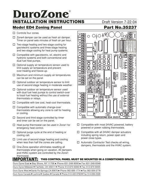
DuroZone DuroZone® INSTALLATION INSTRUCTIONS Draft Version 7-22-04 Model ED4 Zoning Panel Panel Part Part No.35237 Controls four zones. Zone4 damper can be used as fresh air damper. Timer on panel sets minutes of fresh air per hour. Two-stage heating and two-stage cooling for gas/electric systems and three-stage heating and two-stage cooling for heat pump systems. Compatible with gas/electric, oil, electric and hydronic systems and both conventional and dual fuel heat pumps. Optional supply air temperature sensor used to limit supply air temperature and prevent over-heating and freeze-up. Maximum and minimum supply air temperatures can be set on the panel. Optional outdoor air temperature sensor to limit use of second stage heating in moderate weather. Optional outdoor air temperature sensor used with dual fuel heat pumps to control switch-over to fossil fuel heating without the use of external thermostats or relays. Compatible with low cost, heat-cool thermostats. Compatible with automatic change-over thermostats allowing any zone to call for heating or cooling. Second and third stage controlled by timer and timer can be set on the panel. Heat pump thermostat can be used in Zone1 for emergency heat control. Optional purge cycle at the end of heating or cooling call. Limit use of second stage heating and cooling when less than half the zones are calling. One-Zone operation eliminates resetting all thermostats when going on vacation. All dampers and HVAC system are controlled by the Zone1 thermostat. IMPORTANT: Duro Dyne East Bay Shore, NY 11706 Phone 631-249-9000 Fax 631-249-8346 Duro Dyne Midwest Fairfield, OH 45011 Phone 513-870-6000 Fax 513-870-6005 Duro Dyne West Sante Fe Springs,CA 90670 Phone 562-926-1774 Fax 562-926-5778 Duro Dyne Canada Lachine Quebec Canada Phone 514-422-9760 Fax 514-636-0328 M1 D MM2 PR4 M4 M6 M1 D MM2 PR3 M4 M6 M1 D MM2 PR2 M4 M6 M1 D MM2 PR1 M4 M6 SAS SAS OAS OAS Y2 G W2/E Y1 W1/B O RH RC RH-RC JUMPER DPR3 DPR1 DPR4 DPR2 CAP LIMIT FAN 20 15 25 10 30 5 35 W2/Y2 TMR 42 30 40 45 20 40 37 47 10 50 35 50 0 60 CLG LIMIT FA TIMER 140 130 150 45 40 50 120 160 35 55 110 170 30 60 HTG LIMIT ODT LIMIT SAT LIMIT OAS LIMIT COOL HEAT STATUS FA CYCEMHEAT TIMER RESET DuroZone RP4 VERSION 1.20 Copyright BAC 2004 WIRELESS DATA DUROZONE ED4 35237 ON 1ZNE OFF ON OFF EMERGENCY HEAT Compatible with most 24VAC powered, battery powered or power robbing thermostats. Compatible with all 24VAC damper actuators including spring return, power open and power close types. Automatic Contractor Test checks all wiring, dampers, thermostats and the HVAC system. NO 1 2 24VAC FAD ◄ DPR4 ► ZN4 20M ◄ OPSYS ► NO YES ◄ ODLMT ► NO YES ◄ C LMT ► NO NO ◄ PRGE ► 90S HP ◄ TSTAT ► GE EL ◄ FAN ► GAS DF ◄ HP ► CON HP ◄ SYS ► GE THIS CONTROL PANEL MUST BE MOUNTED IN A CONDITIONED SPACE. 1ZNE G T Y S T W A T C 4 R G T Y S T W A T C 3 R G T Y S T W A T C 2 R W2/E T G S T Y1 A O T 1 W1/B C R
- Page 2 and 3: The ED4 is a 4-zone panel that can
- Page 4 and 5: Cooling Limit Potentiometer This po
- Page 6 and 7: COMPRESSOR2 COMPRESSOR1 LINE VOLTAG
- Page 8: Notes Duro Dyne East Division, Bay
<strong>Duro</strong>Zone<br />
<strong>Duro</strong>Zone®<br />
INSTALLATION INSTRUCTIONS Draft Version 7-22-04<br />
Model ED4 Zoning Panel Panel<br />
Part Part No.35237<br />
Controls four zones.<br />
Zone4 damper can be used as fresh air damper.<br />
Timer on panel sets minutes of fresh air per hour.<br />
Two-stage heating and two-stage cooling for<br />
gas/electric systems and three-stage heating<br />
and two-stage cooling for heat pump systems.<br />
Compatible with gas/electric, oil, electric and<br />
hydronic systems and both conventional and<br />
dual fuel heat pumps.<br />
Optional supply air temperature sensor used to<br />
limit supply air temperature and prevent<br />
over-heating and freeze-up.<br />
Maximum and minimum supply air temperatures<br />
can be set on the panel.<br />
Optional outdoor air temperature sensor to limit<br />
use of second stage heating in moderate weather.<br />
Optional outdoor air temperature sensor used<br />
with dual fuel heat pumps to control switch-over<br />
to fossil fuel heating without the use of external<br />
thermostats or relays.<br />
Compatible with low cost, heat-cool thermostats.<br />
Compatible with automatic change-over<br />
thermostats allowing any zone to call for heating<br />
or cooling.<br />
Second and third stage controlled by timer<br />
and timer can be set on the panel.<br />
Heat pump thermostat can be used in Zone1 for<br />
emergency heat control.<br />
Optional purge cycle at the end of heating or<br />
cooling call.<br />
Limit use of second stage heating and cooling<br />
when less than half the zones are calling.<br />
One-Zone operation eliminates resetting all<br />
thermostats when going on vacation. All dampers<br />
and HVAC system are controlled by the Zone1<br />
thermostat.<br />
IMPORTANT:<br />
<strong>Duro</strong> <strong>Dyne</strong> East Bay Shore, NY 11706 Phone 631-249-9000 Fax 631-249-8346<br />
<strong>Duro</strong> <strong>Dyne</strong> Midwest Fairfield, OH 45011 Phone 513-870-6000 Fax 513-870-6005<br />
<strong>Duro</strong> <strong>Dyne</strong> West Sante Fe Springs,CA 90670 Phone 562-926-1774 Fax 562-926-5778<br />
<strong>Duro</strong> <strong>Dyne</strong> Canada Lachine Quebec Canada Phone 514-422-9760 Fax 514-636-0328<br />
M1<br />
D<br />
MM2<br />
PR4<br />
M4<br />
M6<br />
M1<br />
D<br />
MM2<br />
PR3<br />
M4<br />
M6<br />
M1<br />
D<br />
MM2<br />
PR2<br />
M4<br />
M6<br />
M1<br />
D<br />
MM2<br />
PR1<br />
M4<br />
M6<br />
SAS<br />
SAS<br />
OAS<br />
OAS<br />
Y2<br />
G<br />
W2/E<br />
Y1<br />
W1/B<br />
O<br />
RH<br />
RC<br />
RH-RC<br />
JUMPER<br />
DPR3<br />
DPR1<br />
DPR4<br />
DPR2<br />
CAP<br />
LIMIT<br />
FAN<br />
20<br />
15 25<br />
10 30<br />
5 35<br />
W2/Y2 TMR<br />
42 30<br />
40 45 20 40<br />
37 47 10 50<br />
35 50 0 60<br />
CLG LIMIT FA TIMER<br />
140<br />
130 150<br />
45<br />
40 50<br />
120 160 35 55<br />
110 170 30 60<br />
HTG LIMIT ODT LIMIT<br />
SAT<br />
LIMIT<br />
OAS<br />
LIMIT<br />
COOL HEAT<br />
STATUS FA CYCEMHEAT<br />
TIMER<br />
RESET<br />
<strong>Duro</strong>Zone RP4<br />
VERSION 1.20<br />
Copyright BAC 2004<br />
WIRELESS<br />
DATA<br />
DUROZONE ED4 35237<br />
ON<br />
1ZNE<br />
OFF<br />
ON OFF<br />
EMERGENCY<br />
HEAT<br />
Compatible with most 24VAC powered, battery<br />
powered or power robbing thermostats.<br />
Compatible with all 24VAC damper actuators<br />
including spring return, power open and<br />
power close types.<br />
Automatic Contractor Test checks all wiring,<br />
dampers, thermostats and the HVAC system.<br />
NO<br />
1<br />
2<br />
24VAC<br />
FAD ◄ DPR4 ► ZN4<br />
20M ◄ OPSYS ► NO<br />
YES ◄ ODLMT ► NO<br />
YES ◄ C LMT ► NO<br />
NO ◄ PRGE ► 90S<br />
HP ◄ TSTAT ► GE<br />
EL ◄ FAN ► GAS<br />
DF ◄ HP ► CON<br />
HP ◄ SYS ► GE<br />
THIS CONTROL PANEL MUST BE MOUNTED IN A CONDITIONED SPACE.<br />
1ZNE<br />
G<br />
T<br />
Y S<br />
T<br />
W A<br />
T<br />
C 4<br />
R<br />
G<br />
T<br />
Y S<br />
T<br />
W A<br />
T<br />
C 3<br />
R<br />
G<br />
T<br />
Y S<br />
T<br />
W A<br />
T<br />
C 2<br />
R<br />
W2/E<br />
T<br />
G S<br />
T<br />
Y1 A<br />
O T<br />
1<br />
W1/B<br />
C<br />
R
The ED4 is a 4-zone panel that can control gas/electric,<br />
hydronic, electric and both conventional and dual fuel heat<br />
pumps with two heating stages and one cooling stage.<br />
Low cost heat-cool thermostats can be used in all zones<br />
and optionally a heat pump type thermostat can be used<br />
in Zone1.<br />
Selecting Equipment Options<br />
DIP switches 1, 2 and 3 select the type of HVAC system<br />
that is being used. The panel is factory set for a<br />
gas/electric system with Gas fan operation.<br />
FAD ◄ DPR4 ► ZN4<br />
20M ◄ OPSYS ► NO<br />
YES ◄ ODLMT ► NO<br />
YES ◄ C LMT ► NO<br />
NO ◄ PRGE ►90S<br />
HP ◄ TSTAT ►GE<br />
EL ◄ FAN ► GAS<br />
DF ◄ HP ► CON<br />
HP ◄ SYS ► GE<br />
Selecting Gas-Electric or Heat Pump System<br />
The panel will operate with gas-electric, oil, hydronic<br />
and electric HVAC systems when DIP switch #1 is in the<br />
Off position. The panel will operate with heat pump<br />
systems when DIP switch #1 is in the On position.<br />
Selecting Conventional or Dual Fuel<br />
Heat Pump System<br />
When DIP switch #1 is set to select heat pump<br />
operation, DIP switch #2 selects a conventional heat<br />
pump or a dual fuel heat pump.<br />
For conventional heat pumps the panel will activate<br />
stage one and two compressors (Y1 and Y2). In third<br />
stage heating the panel will activate both compressors<br />
and the secondary heating (W2). For dual fuel heat<br />
pumps only the secondary heating (W2) is activated<br />
during third stage heating calls.<br />
Selecting Gas or Electric Fan Operation<br />
DIP switch #3 selects Gas or Electric indoor fan<br />
operation. In Gas mode the fan is not turned On by the<br />
panel during a heating call. The plenum sensor in the<br />
furnace automatically turns the fan On when the plenum<br />
temperature rises.<br />
In Electric operation, the panel turns the fan On during<br />
heating calls. Selecting a heat pump system will<br />
automatically turn the fan On during heating calls. If a<br />
dual fuel heat pump is used, DIP switch #3 selects<br />
whether the fan is operated during calls using the<br />
auxillary fuel system for heating.<br />
In both gas-electric and heat pump systems, the indoor<br />
fan is activated during cooling calls.<br />
Page 2<br />
NO<br />
Selecting Type of Thermostat in Zone1<br />
DIP switch #4 selects the type of thermostat being used in<br />
Zone1. For heat pump systems, a heat pump thermostat<br />
may be selected for Zone1 to provide emergency heat<br />
control on the thermostat.<br />
Emergency heat can also be controlled by the Emergency<br />
Heat slide switch on the panel or an external switch.<br />
NO NO<br />
FAD ◄ DPR4 ► ZN4<br />
20M ◄ OPSYS ► NO<br />
YES ◄ ODLMT ► NO<br />
YES ◄ C LMT ► NO<br />
NO ◄ PRGE ►90S<br />
HP ◄ TSTAT ►GE<br />
EL ◄ FAN ► GAS<br />
DF ◄ HP ► CON<br />
HP ◄ SYS ► GE<br />
Selecting Purge Control<br />
DIP switch #5 selects whether the heat or cool stored in<br />
the system at the end of a heating or cooling cycle is<br />
purge by the panel. If purge is controlled by the panel, the<br />
indoor fan will be operated for 90 seconds at the end of a<br />
heating or cooling call to purge the stored heat or cold.<br />
During purge the dampers will remain in the postion just<br />
before purge and purged air goes to the last zones calling.<br />
FAD ◄ DPR4 ► ZN4<br />
20M ◄ OPSYS ► NO<br />
YES ◄ ODLMT ► NO<br />
YES ◄ C LMT ► NO<br />
NO ◄ PRGE ►90S<br />
HP ◄ TSTAT ►GE<br />
EL ◄ FAN ► GAS<br />
DF ◄ HP ► CON<br />
HP ◄ SYS ► GE<br />
Selecting Capacity Limit Control<br />
DIP switch #6 selects whether second stage heating or<br />
cooling will be inhibited if only half the zones are calling for<br />
heating or cooling.<br />
NO<br />
FAD ◄ DPR4 ► ZN4<br />
20M ◄ OPSYS ► NO<br />
YES ◄ ODLMT ► NO<br />
YES ◄ C LMT ► NO<br />
NO ◄ PRGE ►90S<br />
HP ◄ TSTAT ►GE<br />
EL ◄ FAN ► GAS<br />
DF ◄ HP ► CON<br />
HP ◄ SYS ► GE<br />
Selecting Outdoor Temperature Limit Control<br />
DIP switch #7 selects whether stage two heating will be<br />
disabled if the outdoor temperature is above the<br />
temperature set on the ODT Limit potentiometer.<br />
In dual fuel heat pumps, switch #7 selects if the heat<br />
pump automatically switches to the secondary heating<br />
system when the outdoor temperature drops below the<br />
temperature set on the ODT Limit potentiometer.<br />
NO<br />
FAD ◄ DPR4 ► ZN4<br />
20M ◄ OPSYS ► NO<br />
YES ◄ ODLMT ► NO<br />
YES ◄ C LMT ► NO<br />
NO ◄ PRGE ►90S<br />
HP ◄ TSTAT ►GE<br />
EL ◄ FAN ► GAS<br />
DF ◄ HP ► CON<br />
HP ◄ SYS ► GE
Selecting Opposite System Service<br />
The panel will normally service heating or cooling based<br />
on whether there are more heating or more cooling calls.<br />
If Opposite System service is selected using DIP switch<br />
#8 , the panel will switch to the opposed system after<br />
calling continuously for 20 minutes even though there may<br />
be only one zone calling for the opposed system.<br />
NO NO<br />
Selecting Use of Zone4 Damper<br />
Dip switch #9 selects whether Damper4 is being used as<br />
Zone4 damper or as a fresh air damper. When used as a<br />
fresh air damper, the minutes per hour of fresh can be set<br />
on the panel.<br />
Selecting One-Zone Operation<br />
The panel can be operated as a single or one-zone<br />
system. The panel will control all the dampers together<br />
based on the Zone1 thermostat.<br />
This can eliminate the need to change all the thermostats<br />
when the home or building is vacant such as at night or<br />
during vacation periods.<br />
One-Zone operation can be selected using the 1ZNE<br />
switch on the panel or an external switch switch. The LED<br />
adjacent to the switch will be activated when One-Zone<br />
operation is selected.<br />
1ZNE<br />
ON<br />
FAD ◄ DPR4 ► ZN4<br />
20M ◄ OPSYS ► NO<br />
YES ◄ ODLMT ► NO<br />
YES ◄ C LMT ► NO<br />
NO ◄ PRGE ► 90S<br />
HP ◄ TSTAT ► GE<br />
EL ◄ FAN ► GAS<br />
DF ◄ HP ► CON<br />
HP ◄ SYS ► GE<br />
FAD ◄ DPR4 ► ZN4<br />
20M ◄ OPSYS ► NO<br />
YES ◄ ODLMT ► NO<br />
YES ◄ C LMT ► NO<br />
NO ◄ PRGE ► 90S<br />
HP ◄ TSTAT ► GE<br />
EL ◄ FAN ► GAS<br />
DF ◄ HP ► CON<br />
HP ◄ SYS ► GE<br />
1ZNE<br />
OFF<br />
If an emergency heat call is initiated by a heat pump<br />
thermostat in Zone1, an emergency heat call will occur.<br />
The panel will treat all calls for heating as emergency heat<br />
calls until Zone1 calls for a non-emergency heat call or a<br />
cooling call.<br />
Timer Reset Switch<br />
Momentarily pressing the Timer Reset switch<br />
clears the built-in timers allowing the system to<br />
be checked out more quickly.<br />
Holding the Timer Reset switch for 10 seconds<br />
will activate the Automatic Contractor Test that<br />
checks the system out completely. The<br />
Automatic Contractor Test is described later.<br />
24VAC Power<br />
24VAC is connected to the panel at the terminals marked<br />
24VAC. A 40VA transformer should be used and the<br />
output connected to terminals 1 and 2 (not polarized). A<br />
circuit breaker type fuse is located next to the terminals. If<br />
a short should occur in the damper or thermostat wiring,<br />
the Fuse will open the circuit and then close the circuit<br />
when the short is removed.<br />
FUSE<br />
Wireless Data Connector<br />
24VAC<br />
This connector is provide for future wireless<br />
thermostats and wireless connection to a PC<br />
computer that can be used to monitor the<br />
zoning system.<br />
1<br />
2<br />
TIMER<br />
RESET<br />
WARNING!<br />
THE FUSE GETS VERY HOT WHEN A SHORT<br />
OCCURS AND SHOULD NOT BE TOUCHED.<br />
WIRELESS<br />
DATA<br />
Emergency Heat Operation<br />
Emergency heat can be selected from a<br />
heat pump thermostat in Zone1, the<br />
Emergency Heat switch on the panel or<br />
an external switch.<br />
If emergency heat is activated by the<br />
panel switch or an external switch, the<br />
LED adjacent to the switch will be lit. Any<br />
heating calls from any thermostat will be<br />
treated as emergency heat calls.<br />
ON OFF<br />
EMERGENCY<br />
HEAT<br />
Heating Limit Potentiometer<br />
This potentiometer sets maximum<br />
temperature allowed in heating. A low cost<br />
Supply Air Sensor can be used to monitor<br />
the temperature and if the supply air<br />
temperature exceeds the set Heating Limit,<br />
the heat is turned off and the indoor fan<br />
activated. After two minutes the heat will<br />
be turned back on if the supply air has<br />
dropped below the Heating Limit.<br />
140<br />
130 150<br />
120 160<br />
110 170<br />
HTG LIMIT<br />
Page 3
Cooling Limit Potentiometer<br />
This potentiometer sets minimum temperature<br />
allowed in cooling. If the supply air<br />
temperature drops below the set Cooling<br />
Limit, the cooling is turned off and the indoor<br />
fan activated. After two minutes the cooling<br />
will be turned back on if the supply air has<br />
risen above the Cooling Limit.<br />
W2/W3/Y2 Timer Potentiometer<br />
Second and third stage heating and second<br />
stage cooling are controlled by a timer. If the<br />
panel has been calling for heating or cooling<br />
longer than the time set on the W2/W3/Y2<br />
Timer potentiometer, the second stage<br />
heating or cooling will be activated provided it<br />
is not inhibited by the Outdoor Temperature<br />
Limit or the Capacity Limit.<br />
ODT Limit Potentiometer<br />
A low cost Outdoor Air Sensor can be used to<br />
monitor the outdoor temperature and if the<br />
outdoor temperature is greater the ODT Limit,<br />
second stage heating is inhibited if the option<br />
was selected.<br />
In a dual fuel heat pump, the ODT Limit is<br />
used to automatically switch the panel to the<br />
secondary heating system.<br />
FA Timer Potentiometer<br />
When Damper4 is used as a fresh air damper,<br />
the minutes of fresh air per hour can be set on<br />
the FA Timer potentiometer. The fresh air<br />
minutes will try to be fullfilled during a heating<br />
or cooling call. If the fresh minutes cannot be<br />
fullfilled during a call, Damper4 will be opened<br />
and the indoor fan activated.<br />
Damper LEDs<br />
The green damper LEDs will light when the<br />
damper is in the open position. A damper<br />
LED will blink if it detects a zone thermostat<br />
is calling for both heating and cooling that<br />
may be caused by a shorted wire.<br />
System LEDs<br />
The nine red LEDs indicate the<br />
status of the HVAC system. Each<br />
LED will indicate by being lit<br />
continuously or blinking.<br />
CAP<br />
LIMIT<br />
FAN<br />
40<br />
37<br />
35<br />
42<br />
45<br />
47<br />
50<br />
CLG LIMIT<br />
15<br />
10<br />
5<br />
20<br />
25<br />
30<br />
35<br />
W2 TIMER<br />
40<br />
35<br />
30<br />
45<br />
50<br />
55<br />
60<br />
ODT LIMIT<br />
20<br />
10<br />
0<br />
30<br />
FA TIMER<br />
DPR3<br />
DPR1<br />
SAT<br />
LIMIT<br />
COOL<br />
40<br />
50<br />
60<br />
DPR4<br />
DPR2<br />
OAS<br />
LIMIT<br />
HEAT<br />
STATUS FA CYCEMHEAT<br />
Fan LED<br />
The Fan LED will be lit continuously when<br />
the panel is in continuous indoor fan<br />
operation. The Fan LED will blink when the<br />
system is in Purge mode.<br />
Cool LED<br />
The Cool LED will be lit continuously when<br />
the panel is calling for first stage cooling.<br />
The Cool LED will blink when the panel is<br />
calling for second stage cooling.<br />
Heat LED<br />
The Heat LED will be lit continuously when<br />
the panel is calling for first stage heating.<br />
The Heat LED will blink when the panel is<br />
calling for second stage heating.<br />
Status LED<br />
The Status LED blinks continuously when<br />
the panel is powered and indicates the<br />
computer is operating properly.<br />
SA Limit LED<br />
The SA Limit LED is on continuously when<br />
a Supply Air Sensor is installed. The SA<br />
Limit LED blinks when the panel is in<br />
supply air limit (Heating or Cooling<br />
temperature exceeded).<br />
ODT Limit LED<br />
The ODT Limit LED is on continuously<br />
when an Outdoor Air Sensor is installed.<br />
The ODT Limit LED blinks when the panel<br />
is inhibiting second stage calls because of<br />
ODT Limit or the dual fuel heat pump has<br />
switched to secondary heating system.<br />
Capacity Limit LED<br />
The Capacity Limit LED is on continuously<br />
when the panel is inhibiting second stage<br />
calls because only one zone is calling for<br />
heating.<br />
Emergency Heating LED<br />
The Emergency Heating LED is on<br />
continuously when the panel is in the<br />
emergency heat mode and will blink during<br />
an emergency heat call.<br />
Fresh Air Cycle LED<br />
The FA Cycle LED is on continuously when<br />
the fresh air damper mode is selected and<br />
blinks when the damper is openned for<br />
fresh air.<br />
FAN<br />
COOL<br />
HEAT<br />
STATUS<br />
SA LMT<br />
ODT LMT<br />
CAP LMT<br />
EM HEAT<br />
FA CYC<br />
Page 4
Wiring Instructions<br />
All wiring should be done in accordance with local and<br />
national codes. Use color-coded, multi-conductor<br />
thermostat wire.<br />
THESE PANELS ARE DESIGNED FOR USE<br />
WITH 24VAC CONTROLS AND SHOULD<br />
NOT BE USED WITH OTHER VOLTAGES.<br />
USE CAUTION TO AVOID ELECTRIC SHOCK<br />
OR DAMAGE TO EQUIPMENT.<br />
Wiring Supply Air Sensor<br />
To install the optional Supply Air Sensor, connect two<br />
wires to the Supply Air Sensor and to the two terminals<br />
marked “SAS” on the panel.<br />
Zone2 or Zone3<br />
G<br />
Y<br />
W<br />
C<br />
R<br />
Heat-Cool Thermostat<br />
G<br />
A heat pump thermostat can be used in Zone1 to provide<br />
emergency heat control from the thermostat. Be sure to<br />
set DIP switch #4 to HP.<br />
Y<br />
W<br />
R<br />
Heat-Cool Thermostat<br />
Supply Air Sensor<br />
The Supply Air Sensor should be installed in the supply<br />
duct so that it measures the supply air temperature.<br />
Wiring Outdoor Air Temperature Sensor<br />
To install the optional Outdoor Air Temperature Sensor,<br />
connect two wires to the Outdoor Air Sensor and to the<br />
two terminals marked “OAS” on the panel.<br />
OAS<br />
OAS<br />
SAS<br />
SAS<br />
Zone1<br />
W2/E<br />
G<br />
Y1<br />
O<br />
W1/B<br />
C<br />
R<br />
E<br />
Wiring HVAC System<br />
The panel can be used with a wide variety of HVAC<br />
systems. Some of the more common configurations are<br />
shown below.<br />
G<br />
Y<br />
O<br />
C<br />
R<br />
Outdoor Air Sensor<br />
The Outdoor Air Temperature Sensor should be installed<br />
outside and in a shaded location.<br />
Wiring Zone Thermostats<br />
All zones can use low cost, heat-cool thermostats as<br />
shown below. Be sure to set DIP switch #4 to HC if a heatcool<br />
thermostat is used in Zone1.<br />
Zone1<br />
W2/E<br />
G<br />
Y1<br />
O<br />
W1/B<br />
C<br />
R<br />
Heat-Cool Thermostat<br />
G<br />
Y<br />
W<br />
R<br />
INDOOR FAN<br />
INDOOR FAN<br />
COMPRESSOR<br />
GAS VALVE<br />
LINE<br />
VOLTAGE<br />
Y2<br />
G<br />
W2<br />
Y1<br />
W1<br />
R<br />
24VAC<br />
C<br />
TWO-STAGE<br />
GAS/ELECTRIC SYSTEM<br />
NO<br />
FAD ◄ DPR4 ► ZN4<br />
20M ◄ OPSYS ► NO<br />
YES ◄ ODLMT ► NO<br />
YES ◄ C LMT ► NO<br />
NO ◄ PRGE ► 90S<br />
HP ◄ TSTAT ► GE<br />
EL ◄ FAN ► GAS<br />
DF ◄ HP ► CON<br />
HP ◄ SYS ► GE<br />
Y2<br />
G<br />
W2/E<br />
Y1<br />
W1/B<br />
O<br />
RH<br />
RC<br />
RH-RC<br />
JUMPER<br />
Page 5
COMPRESSOR2<br />
COMPRESSOR1<br />
LINE<br />
VOLTAGE<br />
INDOOR FAN<br />
COOLING SYSTEM<br />
PRIMARY<br />
CONTROL<br />
CIRCULATOR<br />
RELAY OR HOT<br />
WATER VALVE<br />
COMPRESSOR2<br />
INDOOR FAN<br />
STRIP HEATING<br />
COMPRESSOR1<br />
REVERSING VALVE<br />
REVERSING VALVE<br />
LINE<br />
VOLTAGE<br />
CONVENTIONAL<br />
HEAT PUMP<br />
WITH ELECTRIC<br />
STRIP HEATING<br />
COMPRESSOR2<br />
INDOOR FAN<br />
COMPRESSOR1<br />
REVERSING VALVE<br />
REVERSING VALVE<br />
LINE<br />
VOLTAGE<br />
HEAT PUMP<br />
INDOOR FAN<br />
STAGE2 HTG<br />
STAGE1 HTG<br />
Y2<br />
G<br />
Y<br />
R<br />
24VAC<br />
C<br />
Y2<br />
G<br />
W2<br />
Y1<br />
R<br />
24VAC<br />
C<br />
Y2<br />
G<br />
Y1<br />
R<br />
24VAC<br />
C<br />
G<br />
W2<br />
W1<br />
NO<br />
NO NO<br />
FAD ◄ DPR4 ► ZN4<br />
20M ◄ OPSYS ► NO<br />
YES ◄ ODLMT ► NO<br />
YES ◄ C LMT ► NO<br />
NO ◄ PRGE ► 90S<br />
HP ◄ TSTAT ► GE<br />
EL ◄ FAN ► GAS<br />
DF ◄ HP ► CON<br />
HP ◄ SYS ► GE<br />
Y2<br />
G<br />
W2/E<br />
Y1<br />
W1/B<br />
O<br />
RH<br />
RC<br />
RH-RC<br />
JUMPER<br />
Cut Jumper<br />
Y2<br />
G<br />
W2/E<br />
Y1<br />
W1/B<br />
O<br />
RH<br />
RC<br />
RH-RC<br />
JUMPER<br />
Cut Jumper<br />
FAD ◄ DPR4 ► ZN4<br />
20M ◄ OPSYS ► NO<br />
YES ◄ ODLMT ► NO<br />
YES ◄ C LMT ► NO<br />
NO ◄ PRGE ► 90S<br />
HP ◄ TSTAT ► GE<br />
EL ◄ FAN ► GAS<br />
DF ◄ HP ► CON<br />
HP ◄ SYS ► GE<br />
Wiring Dampers<br />
The panel can be used with any 24VAC power<br />
open/power close or spring return damper. Terminal M1 is<br />
24VAC common, M2 is 24VAC, M4 is 24VAC when the<br />
panel opens the damper and M6 is 24VAC when the panel<br />
closes the damper.<br />
M1<br />
M2<br />
M4<br />
M6<br />
Wiring diagram for fora <strong>Duro</strong>Zone MB, MB, MS, MS, or or RD RD type type damper.<br />
Wiring diagram for a spring return damper that is normally<br />
closed with no power (spring closed).<br />
M1<br />
M2<br />
M4<br />
M6<br />
Wiring diagram for a spring return damper that is normally<br />
open with no power (spring open).<br />
1<br />
2<br />
3<br />
4<br />
5<br />
M1<br />
M2<br />
M4<br />
M6<br />
M1<br />
M2<br />
M4<br />
M6<br />
FOSSIL FUEL<br />
SECONDARY<br />
HEATING<br />
Page 6
Automatic Contractor Test<br />
The Automatic Contractor Test (ATC) can be<br />
started at any time by pressing and holding the<br />
Timer Reset switch for 10 seconds. The test<br />
can be terminated at any time by pressing the<br />
Timer Reset switch again.<br />
Before the test is started all calls are terminated<br />
and all dampers are closed. The Status LED<br />
will be on continuously during the test.<br />
Step1. Zone1 Thermostat Test<br />
The DPR1 led will turn On and the<br />
Cool, Heat, Fan, or EM Heat LED<br />
will turn On indicating the state of<br />
the Zone1 thermostat. If the Cool,<br />
Heat, Fan and EM Heat LEDs are<br />
all off, there is no call at the<br />
thermostat.<br />
Step2. Zone2 Thermostat Test<br />
After a 10 second delay, the DPR2<br />
led will turn On and the Cool, Heat,<br />
Fan, or EM Heat LED will turn On<br />
indicating the state of the Zone2<br />
thermostat.<br />
Step3. Zone3 Thermostat Test<br />
After a 10 second delay, the DPR23<br />
led will turn On and the Cool, Heat,<br />
Fan, or EM Heat LED will turn On<br />
indicating the state of the Zone3<br />
thermostat.<br />
Step4. Zone4 Thermostat Test<br />
After a 10 second delay, the DPR24<br />
led will turn On and the Cool, Heat,<br />
Fan, or EM Heat LED will turn On<br />
indicating the state of the Zone4<br />
thermostat.<br />
You can terminate the test at this<br />
time by pressing the Timer Reset<br />
switch. You might want to change<br />
the thermostats and again run the<br />
test.<br />
DPR1<br />
DPR2<br />
DPR3<br />
DPR3 4<br />
Step5. Damper1 Test<br />
After a 20 second delay, the Damper1 will be<br />
opened and the indoor fan activated. You<br />
should feel airflow at Zone1 but not at the<br />
other zones. The DPR1 LED will be On.<br />
FAN<br />
FAN<br />
FAN<br />
FAN<br />
TIMER<br />
RESET<br />
HEAT<br />
COOL EMHEAT<br />
HEAT<br />
COOL EMHEAT<br />
HEAT<br />
COOL EMHEAT<br />
HEAT<br />
COOL EMHEAT<br />
DPR1<br />
Step6. Damper2 Test<br />
After a 20 second delay, the Damper2 will be<br />
opened and the indoor fan activated. You<br />
should feel airflow at Zone2 but not at the<br />
other zones. The DPR2 LED will be On.<br />
Step7. Damper3 Test<br />
After a 20 second delay, the Damper3 will be<br />
opened and the indoor fan activated. You<br />
should feel airflow at Zone3 but not at the<br />
other zones. The DPR3 LED will be On.<br />
Step8. Damper4 Test<br />
After a 20 second delay, the Damper4 will be<br />
opened and the indoor fan activated. If<br />
Damper4 is used as a zone damper you<br />
should feel airflow at Zone4 but not at the<br />
other zones. The DPR4 LED will be On.<br />
If Damper4 is used as a fresh air damper you<br />
shold check the intake air.<br />
Step9. Stage1 Heating Test<br />
After a 30 second delay, all dampers will be<br />
opened and the stage1 heating activated.<br />
Check that heated air is entering the zones.<br />
The Heat LED will be On continuously.<br />
Step10. Stage2 Heating Test<br />
After a 2 minute delay, the stage2 heating is<br />
also activated. Check that heated air is<br />
entering the zones. The Heat LED will be<br />
blinking. blink.<br />
Step11. Stage3 Heating Test<br />
If a heat pump is selected, the third stage<br />
heating will be activated for 2 minutes. The<br />
heating will be turned off and the indoor fan<br />
run for 2 minutes to purge the heat. The Fan<br />
LED will blink during the purge cycle.<br />
Step11. Stage1 Cooling Test<br />
The Stage1 cooling is now turned On and<br />
Cool LED will be On. Check that cool air is<br />
entering the zones.<br />
Step12. Stage2 Cooling Test<br />
After 2 minutes the Stage2 cooling is also<br />
turned On and Cool LED will blink. Check that<br />
cool air is entering the zones.<br />
After the stage2 cooling has run for 2 minutes<br />
the cooling will be turned Off. The indoor fan<br />
will run for 2 minutes to purge the cooling. The<br />
Fan LED will blink during the purge and after 2<br />
minutes the panel will return to normal<br />
operation.<br />
DPR2<br />
DPR3<br />
DPR3 4<br />
HEAT<br />
HEAT<br />
FAN<br />
COOL<br />
COOL<br />
FAN<br />
Page 7
Notes<br />
<strong>Duro</strong> <strong>Dyne</strong> East Division, Bay Shore, NY..............631-249-9000 Fax: 631-249-8346<br />
<strong>Duro</strong> <strong>Dyne</strong> Midwest Division, Fairfield, OH...........513-870-6000 Fax: 513-870-6005<br />
<strong>Duro</strong> <strong>Dyne</strong> West Division, Santa Fe Springs, CA...562-926-1774 Fax: 562-926-5778<br />
<strong>Duro</strong> <strong>Dyne</strong> Canada, Lachine, Quebec, Canada... 514-422-9760 Fax: 514-636-0328<br />
www.durodyne.com E-mail: durodyne@durodyne.com<br />
<br />
®<br />
c 2004 <strong>Duro</strong> <strong>Dyne</strong> Corp.<br />
Printed in USA 09/2004<br />
BP035237


