RED-4 Wiring Instructions - Duro Dyne
RED-4 Wiring Instructions - Duro Dyne RED-4 Wiring Instructions - Duro Dyne
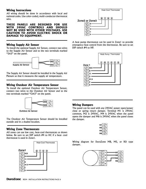
Wiring Instructions All wiring should be done in accordance with local and national codes. Use color-coded, multi-conductor thermostat wire. THESE PANELS ARE DESIGNED FOR USE WITH 24VAC CONTROLS AND SHOULD NOT BE USED WITH OTHER VOLTAGES. USE CAUTION TO AVOID ELECTRIC SHOCK OR DAMAGE TO EQUIPMENT. Wiring Supply Air Sensor To install the optional Supply Air Sensor, connect two wires to the Supply Air Sensor and to the two terminals marked “SAS” on the panel. A heat pump thermostat can be used in Zone1 to provide emergency heat control from the thermostat. Be sure to set DIP switch #4 to HP. The Supply Air Sensor should be installed in the Supply Air Plenum so that it measures the supply air temperature. Wiring Outdoor Air Temperature Sensor To install the optional Outdoor Air Temperature Sensor, connect two wires to the Outdoor Air Sensor and to the two terminals marked “OAS” on the panel. The Outdoor Air Temperature Sensor should be installed outside and in a shaded location. Wiring Dampers The panel can be used with any 24VAC power open/power close or spring return damper. Terminal M1 is 24VAC common, M2 is 24VAC, M4 is 24VAC when the panel opens the damper and M6 is 24VAC when the panel closes the damper. Wiring Zone Thermostats All zones can use low cost, heat-cool thermostats as shown below. Be sure to set DIP switch #4 to HC if a heat- cool thermostat is used in Zone1. Wiring diagram for DuroZone MB, MS, or RD type damper. DuroZone RED4 - Installation INSTRUCTIONS PAGE 6
<strong>Wiring</strong> <strong>Instructions</strong><br />
All wiring should be done in accordance with local and<br />
national codes. Use color-coded, multi-conductor thermostat<br />
wire.<br />
THESE PANELS ARE DESIGNED FOR USE<br />
WITH 24VAC CONTROLS AND SHOULD<br />
NOT BE USED WITH OTHER VOLTAGES. USE<br />
CAUTION TO AVOID ELECTRIC SHOCK OR<br />
DAMAGE TO EQUIPMENT.<br />
<strong>Wiring</strong> Supply Air Sensor<br />
To install the optional Supply Air Sensor, connect two wires<br />
to the Supply Air Sensor and to the two terminals marked<br />
“SAS” on the panel.<br />
A heat pump thermostat can be used in Zone1 to provide<br />
emergency heat control from the thermostat. Be sure to set<br />
DIP switch #4 to HP.<br />
The Supply Air Sensor should be installed in the Supply Air<br />
Plenum so that it measures the supply air temperature.<br />
<strong>Wiring</strong> Outdoor Air Temperature Sensor<br />
To install the optional Outdoor Air Temperature Sensor,<br />
connect two wires to the Outdoor Air Sensor and to the<br />
two terminals marked “OAS” on the panel.<br />
The Outdoor Air Temperature Sensor should be installed<br />
outside and in a shaded location.<br />
<strong>Wiring</strong> Dampers<br />
The panel can be used with any 24VAC power open/power<br />
close or spring return damper. Terminal M1 is 24VAC<br />
common, M2 is 24VAC, M4 is 24VAC when the panel<br />
opens the damper and M6 is 24VAC when the panel closes<br />
the damper.<br />
<strong>Wiring</strong> Zone Thermostats<br />
All zones can use low cost, heat-cool thermostats as shown<br />
below. Be sure to set DIP switch #4 to HC if a heat- cool<br />
thermostat is used in Zone1.<br />
<strong>Wiring</strong> diagram for <strong>Duro</strong>Zone MB, MS, or RD type<br />
damper.<br />
<strong>Duro</strong>Zone <strong>RED</strong>4 - Installation INSTRUCTIONS PAGE 6
<strong>Wiring</strong> diagram for a spring return damper that is normally<br />
closed with no power (spring closed).<br />
<br />
FIRST STAGE<br />
COOLING Y1<br />
SECOND STAGE<br />
COOLING<br />
Y2<br />
COMMON C<br />
<br />
LINE<br />
VOLTAGE<br />
FAN<br />
G<br />
R<br />
24VAC<br />
C<br />
<strong>RED</strong>4 Panel<br />
Y2<br />
G<br />
W2/E<br />
Y1<br />
W1/B<br />
O<br />
RH<br />
RC<br />
RH-RC<br />
JUMPER<br />
<br />
<strong>Wiring</strong> diagram for a spring return damper that is normally<br />
open with no power (spring open).<br />
OIL BURNER<br />
CIRCULATOR RELAY OR<br />
HOT WATER VALVE<br />
<strong>Wiring</strong> HVAC System<br />
The panel can be used with a wide variety of HVAC systems.<br />
Some of the more common configurations follow:<br />
PLEASE NOTE: The <strong>RED</strong>4 panel must<br />
be powered by an independent low<br />
voltage power supply and not by the<br />
equipment low voltage power supply.<br />
<br />
FIRST STAGE<br />
COOLING<br />
SECOND STAGE<br />
COOLING<br />
COMMON<br />
FIRST STAGE<br />
HEATING<br />
SECOND STAGE<br />
HEATING<br />
FAN<br />
FAN SPEED<br />
<br />
LINE<br />
VOLTAGE<br />
Y2<br />
C<br />
G<br />
MULTI STAGE<br />
GAS/ELECTRIC SYSTEM<br />
<br />
Y1<br />
W1<br />
W2<br />
Y<br />
R<br />
24VAC<br />
C<br />
<strong>RED</strong>4 Panel<br />
G<br />
W2/E<br />
Y1<br />
W1/B<br />
O<br />
RH<br />
RC<br />
RH-RC<br />
JUMPER<br />
*NOTE 1: Sometimes Y needs to be wired to the<br />
furnace for fan speed.<br />
Y2<br />
HEAT PUMP<br />
24VAC<br />
FIRST STAGE<br />
SECOND STAGE<br />
REVERSING VALVE<br />
COOLING<br />
DEFROST<br />
AIR HANDLER<br />
ELECTRIC<br />
STRIP HEAT<br />
FAN<br />
LINE<br />
VOLTAGE<br />
24VAC<br />
FIRST STAGE<br />
SECOND STAGE<br />
REVERSING VALVE<br />
COOLING<br />
DEFROST<br />
<br />
FIRST STAGE<br />
SECOND STAGE<br />
FAN<br />
<br />
LINE<br />
VOLTAGE<br />
R<br />
C<br />
Y1<br />
Y2<br />
O<br />
W<br />
W<br />
G<br />
R<br />
24VAC<br />
Heat Pump<br />
C<br />
R<br />
C<br />
Y1<br />
Y2<br />
O<br />
W<br />
W1<br />
W2<br />
G<br />
Y<br />
R<br />
24VAC<br />
C<br />
Y1<br />
W1/B*<br />
Y2<br />
G<br />
W2/E<br />
<strong>RED</strong>4 Panel<br />
Y1<br />
W1/B<br />
<br />
O<br />
RH<br />
RH<br />
RC<br />
Y2<br />
G<br />
W2/E<br />
O<br />
RC<br />
RH-RC<br />
JUMPER<br />
*Wire the<br />
W1/B to<br />
heat pump<br />
if valve<br />
reverses in<br />
the heat<br />
mode.<br />
<strong>RED</strong>4 Panel<br />
RH-RC<br />
JUMPER<br />
<br />
<br />
<br />
<br />
<br />
<br />
<br />
<br />
<br />
<br />
<strong>Duro</strong>Zone <strong>RED</strong>4 - Installation INSTRUCTIONS PAGE 7<br />
*NOTE 1: Sometimes Y needs to be wired to the<br />
furnace for fan speed.


