SmartJoist Design Guide 2011.pub - Tilling Timber
SmartJoist Design Guide 2011.pub - Tilling Timber
SmartJoist Design Guide 2011.pub - Tilling Timber

Create successful ePaper yourself
Turn your PDF publications into a flip-book with our unique Google optimized e-Paper software.
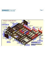
MULTIPLE MEMBER LAMINATING OF SIDE LOADED BEAMS<br />
(Non– symmetrical loading)<br />
Combination 1 Combination 2 Combination 3<br />
2 pieces of<br />
35 or 42 mm<br />
3 pieces of<br />
35 or 42 mm<br />
1 piece of 35 or 42 mm<br />
1 piece of 58 or 75 mm<br />
Nail spacing<br />
50 mm Min<br />
50 mm<br />
Min<br />
Bolt spacing<br />
50 mm Min<br />
Stagger row of bolts<br />
55 mm diameter<br />
washer as per table<br />
4.12 - AS 1720.1<br />
50 mm Min<br />
MAXIMUM FLOOR LOAD WIDTH SUPPORTED BY EITHER OUTSIDE MEMBER (mm)<br />
Combination<br />
(see details above)<br />
3.75Ф x 90 mm nails 12 mm Ф bolts<br />
2 rows at 300<br />
ctrs<br />
3 rows at 300<br />
ctrs<br />
2 rows at 600 ctrs<br />
2 rows at 300<br />
ctrs<br />
Combination 1 3400 5100 7500 15000<br />
Combination 2 2900 4000 5600 11000<br />
Combination 3 2900 4000 4500 11000<br />
Notes:<br />
1. Table values are for 40 kg/m 2 floors.<br />
2. The table values for nails may be doubled for nails at 150 mm centres, and tripled for nails at 100 mm centres<br />
3. The nail schedules shown apply to both sides of a three (3) piece beam<br />
4. Bolts are to be grade 4.6 commercial bolts conforming to AS 1111. Bolt holes are to be a maximum of 13 mm diameter and are to be<br />
located NOT less than 50 mm from either edge.<br />
5. All bolts shall be fitted with a washer at each end, of a size NOT less than that given in AS 1720.1 table 4.11.<br />
HOW TO USE THE MAXIMUM UNIFORM SIDE<br />
LOAD TABLE<br />
Example: see diagram opposite<br />
Floor load width 1 Floor load width 2<br />
= 2800 mm = 2300 mm<br />
Beam of 2 SmartLVL loaded on both side (Combination 1)<br />
FLW 1 = 2800 mm, FLW 2 = 2300 mm<br />
Total FLW = 2800 + 2300 = 5100 mm.<br />
1. Use SmartFrame software or SmartLVL safe load tables to size the two<br />
member section to support the FLW of 5100 mm.<br />
2. Choose the larger of the side FLW's carried by the beam, in this case 2800<br />
mm.<br />
3. Enter the table at the "Combination 1" row and scan across to a table value<br />
greater than 2800 mm. The first value in the row at 3600 mm is greater<br />
than the 2800 mm required.<br />
4. Thus adopt 2 rows of 3.75Ф x 90 mm nails at 300 mm centres<br />
<strong>SmartJoist</strong> <strong>Design</strong> <strong>Guide</strong> 21