AERZENER MASCHINENFABRIK GMBH
AERZENER MASCHINENFABRIK GMBH
AERZENER MASCHINENFABRIK GMBH

Create successful ePaper yourself
Turn your PDF publications into a flip-book with our unique Google optimized e-Paper software.
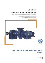
A E R Z E N<br />
S C R E W C O M P R E S S O R S<br />
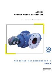
AERZEN - DELTA TWIN - Two Stage Screw Compressors<br />
Oil free compressed air technology<br />
A E R Z E N E R M A S C H I N E N F A B R I K<br />
G M B H<br />
V1-016 03 EN<br />
1000 6.2010
The customer benefits thanks to technical progress<br />
Aerzener Maschinenfabrik have been manufacturing screw compressors since 1943.<br />
As the Market Leader in Europe, the company is one of the oldest and largest manufacturers of twin shaft<br />
positive displacement compressors world-wide.<br />
Based on technical expertise, experienced staff and a constant dialogue with customers, Aerzener Maschinenfabrik<br />
make innovative products. To maintain their success in the market place their products are designed<br />
to benefit the customer and support plant manufacturers.<br />
Application range of the DELTA TWIN<br />
The new series DELTA TWIN is designed for the oil free compression of air and neutral gases. It is especially<br />
suitable for the production of industrial compressed air. The two stage units cover motor sizes from 75 to<br />
200 kW and differential pressures up to 10.5 bars. They are available in water and air cooled design and the<br />
volume flow range is from 500 m³/h up to 2.100 m³/h.<br />
This belt-driven series is supplemented by gear-driven units, water-cooled, up to 355 kW and 3.100 m³/h.<br />
The differential pressures are also up to 10,5 bar.<br />
Application Compressed Air<br />
• foodstuff technology<br />
• pneumatic industry<br />
• medicine production<br />
• beverage industry<br />
• chemistry and process engineering<br />
• medical industry<br />
• breweries<br />
• glass industry<br />
• dairies<br />
• control- and instrument air<br />
• spray-coat plants<br />
• surface technology<br />
• manufacture of PET-bottles<br />
and also in many other branches<br />
2
Construction and installation<br />
The heart of the new series DELTA TWIN forms the<br />
dry-compressing screw compressors being available<br />
as high-pressure and vacuum stages.<br />
Constructive optimization of rotors and housing<br />
ensures an excellent efficiency of the screw compressors.<br />
Unit design<br />
Belt-driven (75 – 200 kW)<br />
The drive of the compressor is carried out via V-belts.<br />
The drive motor is mounted on the hinged motor<br />
support. Thanks to its own weight an optimum belt<br />
tension is guaranteed.<br />
The installation of the new compressed-air units<br />
is clearly subdivided into three groups: the electrical-/drive<br />
range, the compressor- and refrigeration<br />
fields. Therefore, all components parts are optimally<br />
accessible. The units can be delivered in water- and<br />
air-cooled design. The intermediate- and after-coolers<br />
consist of CuNiFe with the standard design at water<br />
side. In case of difficult conditions by e.g. aggressive<br />
cooling water alternative materials can be applied.<br />
The installed control device is combined with an integrated<br />
monitoring- and fault annunciating system with<br />
clear character display. The control device operates<br />
considerably energy-saving. The DELTA TWIN units<br />
are delivered completely assembled, so that a quick<br />
installation and trouble-free commissioning can be<br />
realized.<br />
Unit design<br />
Gear-driven (250 – 355 kW)<br />
The compression is carried out without liquid injection.<br />
The units are assembled ready for connection<br />
and delivered including standardized accessories.<br />
The compact arrangement of accessories needs<br />
only little space. Due to the rotating masses no special<br />
foundation is required. The installation is always<br />
effected with acoustic hood for compressor and drive<br />
motor. The Delta Twin series with gearbox drive is<br />
available in water-cooled design (250 – 355 kW).<br />
With each compressor stage the drive is carried out<br />
by a flanged-on helical gearbox.<br />
Ambient air takes care of the compressor cooling.<br />
Besides a standard instrumentation with electronic<br />
monitoring- and fault annunciating system also the<br />
application of a programmable control system is<br />
possible.<br />
3
Advantages for the customer<br />
• Larger volume flow by improved utilisation of the<br />
motor power.<br />
• Optimal capacity to speed adjustment by belt drive<br />
(patented driving conception)<br />
• Compact, space saving construction.<br />
• Design of the unit allows easy access for maintenance<br />
• All maintenance and service work carried out on<br />
site.<br />
• Customer‘s special requirements possible through<br />
modifications.<br />
• Low sound level<br />
• Safe and reliable operation developed from six decades<br />
of experience in compressor construction.<br />
• Excellent price to performance ratio<br />
Scope of delivery- and performances<br />
Belt-driven<br />
• Aerzen screw compressor stages (vacuum + over<br />
pressure) with reinforced bearing<br />
of drive shaft appropriate for belt drive<br />
• Compressed-oil lubrication including oil pump, oil<br />
filter, oil return valve, turbo filter for oil room relief<br />
• Base support with hinged motor support<br />
• Belt drive with protection<br />
• Electric motor<br />
• Safety relief valve<br />
• Non-return valve<br />
• Intermediate cooler with condensate separator<br />
• After-cooler (condensate separator as option)<br />
• Acoustic hood for the complete compressor unit<br />
for internal installation with flexible machinery<br />
mountings<br />
• Control cabinet with electrical interconnection and<br />
control<br />
• Constant speed unloading device incl. intake throttle<br />
(self-medium controlled)<br />
• Intake filter<br />
Gear-driven<br />
• Aerzen screw compressor stages with integrated<br />
gearbox, compressed oil lubrication incl. oil pump,<br />
oil filter, oil return valve, air-/oil cooler, turbo filter<br />
for oil room relief<br />
• Compressed oil lubrication incl. oil pump, oil filter,<br />
oil return valve, turbo filter for oil room relief<br />
• Base frame for compressor stage and drive motor<br />
(three-phase motor)<br />
• Flexible coupling with protection<br />
• Electric motor<br />
• Safety relief valve<br />
• Non-return valve<br />
• Intermediate cooler with condensate separator<br />
• After-cooler (condensate separator as option)<br />
• Acoustic hood for the complete compressor unit for<br />
internal installation with flexible machinery mountings<br />
• Control cabinet with electrical interconnection and<br />
control<br />
• Constant speed unloading device incl. intake throttle<br />
(self-medium controlled)<br />
• Intake filter<br />
4<br />
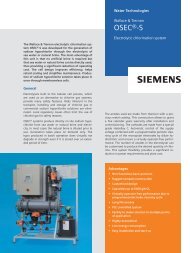
Aerzen Delta Twin unit (belt-driven)
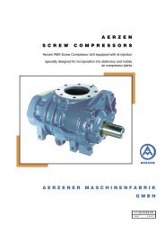
Flow chart DELTA TWIN, water-cooled design type DT . . . WB<br />
cooling water<br />
condensate<br />
control air<br />
compressed air<br />
cooling water<br />
1 Driving motor<br />
2 Belt drive<br />
3 Oil reservoir<br />
4 Compressor 1st stage low pressure<br />
5 Compressor 2nd stage high pressure<br />
6 Intake filter<br />
7 Throttle flap<br />
8 Sound absorbing connection chamber<br />
9 Intermediate cooler<br />
10 Compensator<br />
11 Condensate separator<br />
12 Safety relief valve 1st stage<br />
13 Non-return valve<br />
14 Aftercooler<br />
15 Safety relief valve 2nd stage<br />
16 Connection compensator<br />
compressed air<br />
17 Vent valve<br />
18 Blow-off silencer<br />
19 Solenoid valve<br />
20 Pressure selecting relay<br />
21 Connection compensator<br />
cooling water<br />
22 Safety relief valve cooling water<br />
23 Throttle shut-off valve cooling water<br />
24 Oil pump<br />
25 Oil temperature controller<br />
26 Oil cooler<br />
27 Oil pressure retaining valve<br />
28 Oil filter<br />
29 Solenoid valve<br />
30 Oil filter monitoring<br />
31 Condensate drain intermediate cooler<br />
32 Non-return valve<br />
33 Fan<br />
34 Intake filter monitoring<br />
35 Direction of rotation monitoring<br />
36 Discharge temperature 1st stage<br />
37 Intermediate pressure monitoring<br />
38 Intake temperature 2nd stage<br />
39 Discharge pressure monitoring<br />
40 Discharge temperature 2nd stage<br />
41 Operating pressure sensor<br />
42 Compressed-air outlet temperature<br />
43 Motor temperate monitoring<br />
44 Motor-overcurrent switch<br />
45 Oil level indication<br />
46 Oil temperature monitoring<br />
47 Oil pressure indication<br />
48 Oil pressure monitoring<br />
49 Cooling water temperature at inlet<br />
50 Cooling water temperature at outlet<br />
51 Oil drain<br />
52 Re-lubrication driving motor<br />
53 Oil demister<br />
54 Units-OFF<br />
5
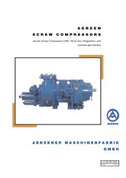
Flow chart DELTA TWIN, air-cooled design type DT . . . AB<br />
condensate<br />
control air<br />
compressed-air<br />
1 Driving motor<br />
2 Belt drive<br />
3 Oil reservoir<br />
4 Compressor 1st stage low pressure<br />
5 Compressor 2nd stage high pressure<br />
6 Intake filter<br />
7 Throttle flap<br />
8 Sound absorbing connection chamber<br />
9 Intermediate cooler<br />
10 Compensator<br />
11 Condensate separator<br />
12 Safety relief valve 1st stage<br />
13 Non-return valve<br />
14 Aftercooler<br />
15 Safety relief valve 2nd stage<br />
16 Connection compensator<br />
compressed air<br />
17 Vent valve<br />
6<br />
18 Blow-off silencer<br />
19 Solenoid valve<br />
20 Pressure selecting relay<br />
24 Oil pump<br />
25 Oil temperature controller<br />
26 Oil cooler<br />
27 Oil pressure retaining valve<br />
28 Oil filter<br />
29 Solenoid valve<br />
30 Oil filter monitoring<br />
31 Condensate drain intermediate cooler<br />
32 Non-return valve<br />
33 Fan<br />
34 Intake filter monitoring<br />
35 Direction of rotation monitoring<br />
36 Discharge temperature 1st stage<br />
37 Intermediate pressure monitoring<br />
38 Intake temperature 2nd stage<br />
39 Discharge pressure monitoring<br />
40 Discharge temperature 2nd stage<br />
41 Operating pressure sensor<br />
42 Compressed-air outlet temperature<br />
43 Motor temperate monitoring<br />
44 Motor-overcurrent switch<br />
45 Oil level indication<br />
46 Oil temperature monitoring<br />
47 Oil pressure indication<br />
48 Oil pressure monitoring<br />
51 Oil drain<br />
52 Re-lubrication driving motor<br />
53 Oil demister<br />
54 Units-OFF<br />
55 Shut-off ball cock<br />
56 Temperature downstream of 1st stage<br />
57 Temperature downstream of 2nd stage<br />
58 Frequency converter for fan motor
Flow chart DELTA TWIN, water-cooled design type DT . . . WG<br />
1 Suction pressure switch<br />
2 Air filter monitoring<br />
3 Pressure gauge suction pressure<br />
1st stage<br />
4 Pressure gauge discharge pressure<br />
1st stage<br />
5 Discharge pressure switch 1st stage<br />
6 Contact thermometer discharge<br />
temperature 1st stage<br />
7 Contact thermometer oil temperature<br />
8 Oil pressure switch<br />
9 Pressure gauge oil pressure<br />
10 Oil level gauge<br />
11 Thermometer suction temperature<br />
2nd stage<br />
12 Contact thermometer discharge<br />
temperature 2nd stage<br />
13 Pressure gauge discharge pressure<br />
2nd stage<br />
14 Discharge pressure switch 2nd stage<br />
15 Discharge temperature indication<br />
16 Pressure switch suction throttle<br />
control<br />
20 Intake filter<br />
21 Throttle flap control<br />
22 3-ways solenoid valve<br />
23 Compressor with gearbox 1st stage<br />
24 Lateral compensator<br />
25 Oil pump with motor<br />
26 Oil temperature controller<br />
27 Oil overflow valve<br />
28 Oil air cooler<br />
29 Oil filter<br />
30 Intermediate cooler<br />
(also possible as air cooler)<br />
31 Compressor with gearbox 2nd stage<br />
32 Connection housing<br />
33 After-cooler<br />
(also possible as air cooler)<br />
34 Water separator<br />
35 Condensate drain<br />
36 Starting strainer<br />
37 Relief valve<br />
38 Blow-off silencer<br />
39 Safety relief valves 1st and 2nd stage<br />
40 Non-return valve<br />
41 Cooling water control valve<br />
42 Safety relief valve cooling water<br />
43 Oil drain valve<br />
44 Oil demister with motor<br />
45 Coupling<br />
46 Driving motor<br />
47 Acoustic hood fan<br />
7
Performance data<br />
DELTA TWIN<br />
size<br />
differential<br />
pressure<br />
volume<br />
flow 2<br />
nominal capacity<br />
main drive<br />
fan motor<br />
water-cooled<br />
fan motor<br />
air-cooled<br />
type of construction<br />
1 bar psig m 3 /h cfm kW HP kW HP kW HP<br />
DT 7/8 AB / WB 8 115 680 400 75 100 0,75 1,0 2 x 3,0 + 0,37 2 x 4,0 + 0,5<br />
DT 7/10 AB / WB 10 150 560 330 75 100 0,75 1,0 2 x 3,0 + 0,37 2 x 4,0 + 0,5<br />
DT 9/8 AB / WB 8 115 872 513 90 120 0,75 1,0 2 x 3,0 + 0,37 2 x 4,0 + 0,5<br />
DT 9/10 AB / WB 10 150 742 437 90 120 0,75 1,0 2 x 3,0 + 0,37 2 x 4,0 + 0,5<br />
DT 11/8 AB / WB 8 115 1125 662 110 150 0,75 1,0 2 x 3,0 + 0,37 2 x 4,0 + 0,5<br />
DT 11/10 AB / WB 10 150 946 554 110 150 0,75 1,0 2 x 3,0 + 0,37 2 x 4,0 + 0,5<br />
DT 13/8 AB / WB 8 115 1301 766 132 180 0,75 1,0 2 x 3,0 + 0,37 2 x 4,0 + 0,5<br />
DT 13/10 AB / WB 10 150 1148 676 132 180 0,75 1,0 2 x 3,0 + 0,37 2 x 4,0 + 0,5<br />
DT 14/8 AB / WB 8 115 1401 825 145 195 0,75 1,0 2 x 3,0 + 0,37 2 x 4,0 + 0,5<br />
DT 14/10 AB / WB 10 150 1279 753 145 195 0,75 1,0 2 x 3,0 + 0,37 2 x 4,0 + 0,5<br />
DT 16/8 AB / WB 8 115 1624 956 160 220 1,1 1,5 2 x 4,0 + 0,55 2 x 5,5 + 0,75<br />
DT 16/10 AB / WB 10 150 1499 882 160 220 1,1 1,5 2 x 4,0 + 0,55 2 x 5,5 + 0,75<br />
DT 20/8 AB / WB 8 115 2053 1208 200 270 1,1 1,5 2 x 4,0 + 0,55 2 x 5,5 + 0,75<br />
DT 20/10 AB / WB 10 150 1824 1074 200 270 1,1 1,5 2 x 4,0 + 0,55 2 x 5,5 + 0,75<br />
DT 25/8 WG 8 115 2233 1314 250 340 3 4,1 - -<br />
DT 25/10 WG 10 150 1905 1121 250 340 3 4,1 - -<br />
DT 31/8 WG 8 115 2888 1699 315 428 3 4,1 - -<br />
DT 31/10 WG 10 150 2544 1497 315 428 3 4,1 - -<br />
DT 35/8 WG 8 115 3114 1832 355 483 3 4,1 - -<br />
DT 35/10 WG 10 150 2854 1679 355 483 3 4,1 - -<br />
Emission sound pressure level acc. to DIN 45635 part 13, 80 dB(A) sound-insulated<br />
1: A = air-cooled / W = water-cooled / B = belt-driven / G = gear-driven<br />
2: volume flow at ambient pressure of 1,0 bar and ambient temperature of 20 °C.<br />
Other designs upon request. Subject to alteration.<br />
8
Dimensions and weights - DELTA TWIN water-cooled<br />
exhaust air<br />
option<br />
compressed-air<br />
outlet<br />
inlet air<br />
cooling water<br />
outlet<br />
cooling water<br />
inlet<br />
condensate<br />
outlet<br />
compressedair<br />
outlet<br />
control air<br />
inlet<br />
electrical<br />
connection<br />
DELTA TWIN<br />
size<br />
type of<br />
construction<br />
1<br />
A<br />
[mm]<br />
B<br />
[mm]<br />
C<br />
[mm]<br />
D<br />
[mm]<br />
E<br />
[mm]<br />
F<br />
[mm]<br />
G<br />
[mm]<br />
H<br />
[mm]<br />
J<br />
[mm]<br />
K<br />
[mm]<br />
L<br />
[mm]<br />
M<br />
[mm]<br />
N<br />
[mm]<br />
O<br />
[mm]<br />
P<br />
[mm]<br />
Q<br />
[mm]<br />
R<br />
[mm]<br />
weight<br />
approx. kg<br />
with motor<br />
DT 7/8 ; DT 7/10 WB 2700 1670 2060 164 790 792 790 72,5 1505 963,5 145 1871 145 1232 197,4 145 70 3100<br />
DT 9/8 ; DT 9/10 WB 2700 1670 2060 164 790 792 790 72,5 1505 963,5 145 1871 145 1232 197,4 145 70 3150<br />
DT 11/8 ; DT 11/10 WB 2700 1670 2060 164 790 792 790 72,5 1505 963,5 145 1871 145 1232 197,4 145 70 3500<br />
DT 13/8 ; DT 13/10 WB 2700 1670 2060 164 790 792 790 72,5 1505 963,5 145 1871 145 1232 197,4 145 70 3600<br />
DT 14/8 ; DT 14/10 WB 2700 1670 2060 164 790 792 790 72,5 1505 963,5 145 1871 145 1232 197,4 145 70 3600<br />
DT 16/8 ; DT 16/10 WB 2850 1770 2150 164 835 842 835 72,5 1605 963,5 145 1871 145 1232 197,4 145 70 3900<br />
DT 20/8 ; DT 20/10 WB 2850 1770 2150 164 835 842 835 72,5 1605 963,5 145 1871 145 1232 197,4 145 70 4150<br />
1: A = air-cooled / W = water-cooled / B = belt-driven Dimensions not binding!<br />
Dimensions and weights - DELTA TWIN air-cooled<br />
exhaust air<br />
compressed-air<br />
outlet<br />
option<br />
compressed-air<br />
outlet<br />
inlet air<br />
control air<br />
inlet<br />
inlet air<br />
condensate<br />
outlet<br />
electrical<br />
connection<br />
DELTA TWIN<br />
size<br />
type of<br />
construction<br />
1<br />
A<br />
[mm]<br />
B<br />
[mm]<br />
C<br />
[mm]<br />
D<br />
[mm]<br />
E<br />
[mm]<br />
F<br />
[mm]<br />
H<br />
[mm]<br />
J<br />
[mm]<br />
K<br />
[mm]<br />
L<br />
[mm]<br />
M<br />
[mm]<br />
N<br />
[mm]<br />
R<br />
[mm]<br />
S<br />
[mm]<br />
weight<br />
approx. kg<br />
with motor<br />
DT 7/8 ; DT 7/10 AB 3100 1670 2510 561,5 790 792 72,5 1505 1843 1041 1871 145,5 50 70 3300<br />
DT 9/8 ; DT 9/10 AB 3100 1670 2510 561,5 790 792 72,5 1505 1843 1041 1871 145,5 50 70 3350<br />
DT 11/8 ; DT 11/10 AB 3100 1670 2510 561,5 790 792 164 1300 1843 1041 1871 145,4 50 70 3700<br />
DT 13/8 ; DT 13/10 AB 3100 1670 2510 561,5 790 792 164 1300 1843 1041 1871 145,4 50 70 3800<br />
DT 14/8 ; DT 14/10 AB 3100 1670 2510 561,5 790 792 164 1300 1843 1041 1871 145,4 50 70 3800<br />
DT 16/8 ; DT 16/10 AB 3300 1770 2600 561,5 790 792 164 1300 1843 1140 1871 145,5 50 70 4100<br />
DT 20/8 ; DT 20/10 AB 3300 1770 2600 561,5 790 792 164 1300 1843 1140 1871 145,5 50 70 4350<br />
1: A = air-cooled / W = water-cooled / B = belt-driven Dimensions not binding!<br />
9
Dimensions and weights - DELTA TWIN water-cooled / gear-driven<br />
option<br />
outlet air<br />
option<br />
outlet air<br />
option<br />
outlet air<br />
outlet air<br />
outlet air<br />
electric<br />
connection<br />
discharge<br />
connection<br />
condensate<br />
drain G1<br />
cooling water<br />
in- outlet<br />
DELTA TWIN<br />
size<br />
type of<br />
construction 1<br />
A<br />
[mm]<br />
B<br />
[mm]<br />
C<br />
[mm]<br />
H<br />
[mm]<br />
K<br />
[mm]<br />
L<br />
[mm]<br />
O<br />
[mm]<br />
P<br />
[mm]<br />
Q<br />
[mm]<br />
R<br />
[mm]<br />
weight approx.<br />
kg with motor<br />
DT 25/8 WG 5000 2050 2850 2320 510 360 280 200 250 300 7300<br />
DT 25/10 WG 5000 2050 2850 2320 510 360 280 200 250 300 7300<br />
DT 31/8 WG 5000 2050 2850 2320 510 360 280 200 250 300 7300<br />
DT 31/10 WG 5000 2050 2850 2320 510 360 280 200 250 300 7300<br />
DT 35/8 WG 5000 2050 2850 2320 510 360 280 200 250 300 7300<br />
DT 35/10 WG 5000 2050 2850 2320 510 360 280 200 250 300 7300<br />
1: A = air-cooled / W = water-cooled / B = belt-driven / G = gear-driven Dimensions not binding!<br />
10
DELTA TWIN SPECIAL<br />
Application in chemistry and petrochemistry e.t.c.<br />
For higher power resp. special cases of applications as per customers’ specification (e.g. ex-protection, chemical<br />
designs, for refineries, compression of Argon and in process technology etc.) the series DELTA TWIN<br />
SPECIAL and VMT are available. Here volume flows from 640 up to 8.860 m 3 /h concerning motor ratings<br />
from 90 up to 1.020 kW and differential pressures up to 10,5 bar abs. can be realized.<br />
Modification possibilities on DTS and VMT<br />
Acoustic hood:<br />
Drive:<br />
Control:<br />
Others:<br />
Inlet – and outlet air filter for acoustic hood (fleece filter with support)<br />
Outdoor installation with mounted shelter<br />
Special coatings (special-varnishes)<br />
Winter design: gravity louvers / hood heating<br />
Desert installation: louvers with sand collector / intake pre-filter<br />
Supply voltage (low voltage) up to 690 V / 50/60 c/s<br />
Supply voltage (high voltage) up to 10 KV / 50/60 c/s<br />
Operation with frequency converter / air – or water-cooled (designed with 100 kW<br />
as separate cabinet)<br />
Remote transmission of analogue signals<br />
Primary control<br />
Use of customer-specific control (e.g. Siemens S7 and similar) and special<br />
instrumentations<br />
Special documentation<br />
Stainless steel designs / special materials<br />
Designs suitable for Ex-areas ATEX<br />
Mobile designs with transport holder<br />
Accessories:<br />
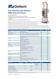
Upon customer’s request AERZEN naturally supplies components to all units for compressed-air processing<br />
(e.g. driers, separators, filters, reservoirs etc.) in all designs.<br />
Upon request AERZEN also offers with its partners complete solutions from compressed-air audit up to<br />
turnkey compressed-air unit.<br />
11
A good address - everywhere<br />
A central point of the Aerzen company policy is the<br />
local presence at the customers.<br />
• 7 sales offi ces in Germany<br />
• 1700 employees worldwide<br />
• more than 30 international subsidiary companies<br />
• representations for more than 100 countries<br />
• more than 100 service technicians on all continents<br />
are the guarantee for competent contact partners<br />
nearby and with the corresponding national<br />
language.<br />
Addresses and communication data under<br />
www.aerzen.com<br />
Local representation<br />
Representation or subsidiary company<br />
Aerzener Maschinenfabrik GmbH<br />
Reherweg 28 . 31855 Aerzen / Germany – P.O. Box 1163 . 31849 Aerzen / Germany<br />
Phone + 49 51 54 / 8 10 . Fax + 49 51 54 / 8 11 91 . www.aerzen.com . info@aerzener.de