63792 Solutions Fall 06-FINAL, page 1-40 @ Normalize - MESco
63792 Solutions Fall 06-FINAL, page 1-40 @ Normalize - MESco
63792 Solutions Fall 06-FINAL, page 1-40 @ Normalize - MESco

You also want an ePaper? Increase the reach of your titles
YUMPU automatically turns print PDFs into web optimized ePapers that Google loves.
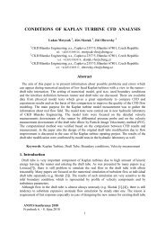
Industry Spotlight<br />
Researchers used ANSYS<br />
simulation technology to develop<br />
a housing for satellite electronic<br />
circuits that is 30 percent lighter<br />
than comparable structures.<br />
The latest addition to the ANSYS<br />
family, FLUENT 6.3 offers new<br />
CFD solver, modeling and other<br />
options.<br />
ANSYS CFX software improves<br />
the design of a hydro-generator<br />
for use in remote areas.
Contents<br />
Industry Spotlight<br />
6<br />
Features<br />
11<br />
14<br />
16<br />
20<br />
Factory and Plant<br />
Equipment<br />
Simulation-driven design plays a<br />
major role in developing industrial<br />
machines for manufacturing and<br />
process facilities around the world.<br />
ANSYS, Inc. Welcomes<br />
Fluent Inc.<br />
ANSYS broadens its opportunities<br />
to provide leading-edge engineering<br />
solutions with the acquisition of<br />
Fluent Inc.<br />
FLUENT 6.3: Major<br />
Advances in CFD Simulation<br />
The latest addition to the ANSYS<br />
family features new solver, modeling<br />
and other options — resulting in<br />
greater speed and flexibility.<br />
Analyzing Composites for<br />
Satellite Components<br />
Researchers used ANSYS software<br />
to study the behavior of a composite<br />
housing for electronic circuits and<br />
quickly developed a design nearly<br />
30 percent lighter than a comparable<br />
aluminum structure.<br />
CFD Simulation<br />
Brings Electrical Power<br />
to Rural Areas<br />
ANSYS CFX software improves the<br />
design and efficiency of a small<br />
hydro-generator for use in remote<br />
areas of developing countries.<br />
Departments<br />
About the cover<br />
Editorial<br />
Tools for Product and Process Innovation ...................2<br />
Industry News<br />
Announcements and Upcoming Events .........................3<br />
Guest Commentary<br />
Integrating CAD and CAE to Enable<br />
Simulation-Driven Design ...................................................................23<br />
Simulation at Work<br />
CFD Simulation Recreates Aviation History ...............24<br />
Weight-Optimized Design of a Commercial<br />
Truck Front Suspension Component ..................................26<br />
Developing Construction Products<br />
with Better Fire Performance .........................................................28<br />
Technology Update<br />
Bringing High-Performance Computing<br />
to the Mainstream . . . . . . . . . . . . . . . . . . . . . . . . . . . . . . . . . . . . . . . . . . . . . . . . . . . . . . . . . . . . . . . . . . . . . . . . . . . . . . . . . . . . .30<br />
Tech File<br />
Running <strong>Solutions</strong> from Macros . . . . . . . . . . . . . . . . . . . . . . . . . . . . . . . . . . . . . . . . . . . . . .33<br />
Tips and Techniques<br />
Working with Coupled-Field Elements . . . . . . . . . . . . . . . . . . . . . . . . . . . . .35<br />
Companies in the factory and<br />
plant equipment market use<br />
engineering simulation extensively,<br />
meeting the challenges<br />
of developing cost-effective,<br />
high-precision and efficient<br />
industrial machines that<br />
must operate under harsh<br />
conditions. Read more in<br />
this issue’s Industry Spotlight<br />
article beginning on <strong>page</strong> 6.<br />
For ANSYS, Inc. sales information, call 1.866.267.9724, or visit www.ansys.com.<br />
To subscribe to ANSYS <strong>Solutions</strong>, go to www.ansys.com/subscribe.<br />
Editorial Director<br />
John Krouse<br />
jkrouse@adelphia.net<br />
Designers<br />
Miller Creative Group<br />
info@millercreativegroup.com<br />
Ad Sales Manager<br />
Beth Mazurak<br />
beth.mazurak@ansys.com<br />
Editorial Advisor<br />
Kelly Wall<br />
kelly.wall@ansys.com<br />
Managing Editor<br />
Fran Hensler<br />
fran.hensler@ansys.com<br />
Art Director<br />
Dan Hart<br />
dan.hart@ansys.com<br />
Circulation Manager<br />
Elaine Travers<br />
elaine.travers@ansys.com<br />
Editorial Contributor<br />
Chris Reeves<br />
chris.reeves@ansys.com<br />
ANSYS <strong>Solutions</strong> is published for ANSYS, Inc. customers, partners and others interested in the field of design and analysis applications.<br />
Neither ANSYS, Inc. nor the editorial director nor Miller Creative Group guarantees or warrants accuracy or completeness of the material contained in this publication. ANSYS,<br />
ANSYS Workbench, CFX, AUTODYN, FLUENT and any and all ANSYS, Inc. product and service names are registered trademarks or trademarks of ANSYS, Inc. or its subsidiaries<br />
located in the United States or other countries. ICEM CFD is a trademark licensed by ANSYS, Inc. All other trademarks or registered trademarks are the property of their respective<br />
owners. POSTMASTER: Send change of address to ANSYS, Inc., Southpointe, 275 Technology Drive, Canonsburg, PA 15317 USA.<br />
©20<strong>06</strong> ANSYS, Inc. All rights reserved.<br />
www.ansys.com ANSYS <strong>Solutions</strong> | Volume 7, Issue 4 20<strong>06</strong>
Editorial<br />
2<br />
Tools for Product and Process Innovation<br />
Simulation technology enables companies to stand out from the crowd with<br />
knock-out designs and leading-edge product development processes.<br />
Innovate or evaporate. That’s<br />
the new business imperative.<br />
Until recently, getting a product<br />
to market faster, cheaper and<br />
better than the competition<br />
usually was good enough.<br />
Not anymore. Now — in addition<br />
to time-to-market, cost and<br />
quality — manufacturers must<br />
focus on innovation: designs<br />
By John Krouse that take the market by storm<br />
Editorial Director and leading-edge development<br />
ANSYS <strong>Solutions</strong> processes that transform<br />
jkrouse@adelphia.net<br />
conceptual ideas into saleable,<br />
reliable and cost-effective<br />
products.<br />
Products must stand apart from others, breaking<br />
new ground in performance, size capacity or other<br />
attributes that compel consumers to pick a particular<br />
item from among many, or that influence OEMs to do<br />
business with one supplier over another. In many<br />
cases, companies improve existing products with<br />
imaginative functions and enhancements. Other times<br />
they create whole new classes of products that totally<br />
dominate a market segment as competitors scramble<br />
to catch up. In a world economy of radical change and<br />
fast-moving trends, innovation has emerged as the big<br />
market differentiator.<br />
Innovation is clearly on the minds of top executives,<br />
as reflected in a second annual survey on the<br />
topic conducted by The Boston Consulting Group in<br />
conjunction with BusinessWeek magazine. They<br />
received input from 1,000 senior managers worldwide,<br />
making it their “deepest management survey to date<br />
on this critical issue.” The report, “The World’s Most<br />
Innovative Companies,” discusses the importance of<br />
design as a differentiator as well as how companies<br />
are rewiring themselves to operate differently, with<br />
72 percent of senior executives in the survey naming<br />
innovation as one of their top priorities.<br />
One of the most interesting parts of the report is a<br />
list of the top 25 innovative companies. Of the top 20,<br />
14 are industrial companies — and ANSYS users. The<br />
others include a coffeehouse chain, retail stores, air-<br />
lines and Internet firms. Last year’s list reflected much<br />
the same.<br />
The use of ANSYS by the world’s most innovative<br />
companies comes as no surprise, of course.<br />
Simulation-driven design is the basis for innovative<br />
development processes and product concepts at a<br />
wide range of companies in nearly all manufacturing<br />
industries. The ability to quickly perform what-if<br />
studies and readily evaluate alternative designs<br />
gives engineers valuable insight into product behavior,<br />
lets them make intelligent trade-off decisions and<br />
provides the freedom not only to imagine way-out<br />
ideas but to easily test their feasibility. Design<br />
optimization and sensitivity studies augment<br />
engineering creativity and serve as guides to creative<br />
solutions that are not always intuitively obvious.<br />
Using these and other wide-ranging capabilities,<br />
virtual prototyping can simulate an entire system or<br />
subsystem in its operating environments to study and<br />
refine real-world product performance, thus enabling<br />
engineers to develop workable innovative designs for<br />
products that otherwise might turn out to be flops in<br />
the market because of performance, warranty or<br />
reliability issues. Moreover, visualization of analysis<br />
results that vividly depict product performance<br />
facilitates close collaboration and synergy between<br />
members of multidisciplinary teams in which people<br />
synergistically create imaginative design concepts<br />
that might not have surfaced otherwise.<br />
In this manner, simulation-driven design leverages<br />
the creativity of engineers and the intellectual<br />
capital of the enterprise. This elevates the approach to<br />
a strategic role as an innovation enabler, allowing<br />
manufacturers who make smart use of the technology<br />
to establish their brand value, strengthen their market<br />
position and boost top-line revenue growth by<br />
developing winning products.■<br />
www.ansys.com ANSYS <strong>Solutions</strong> | Volume 7, Issue 4 20<strong>06</strong>
Industry News<br />
Recent Announcements<br />
and Upcoming Events<br />
3<br />
ANSYS Chosen as CAE Software for Chinese<br />
Mechanical Design Engineer Qualification<br />
The Chinese Mechanical Engineering Society (CMES)<br />
and the Examination Center of Ministry of Education<br />
have formally incorporated ANSYS software into<br />
China’s national Mechanical Design Engineer (MDE)<br />
qualification examination. MDE certification was begun<br />
in China in April 20<strong>06</strong>. It is designed to improve the skill<br />
level of professionals in the Chinese manufacturing<br />
sector, which also widely uses ANSYS software for<br />
computer-aided engineering (CAE).<br />
CMES is a professional society engaged in promoting<br />
the art and science of mechanical engineering<br />
throughout its host nation. In 2005, the Mechanical<br />
Design Institution (MDI) of CMES approached ANSYS<br />
China about using the software in developing a<br />
standard examination to certify mechanical engineers.<br />
The first-ever MDE qualification examination was held<br />
in test centers located in eight Chinese provinces, with<br />
619 students from more than 20 renowned universities<br />
participating. More than <strong>40</strong>0 passed the exam and<br />
received the MDE qualification certificate.<br />
ANSYS Named to Honor Roll<br />
ANSYS, Inc. has been named to the software industry<br />
Sustained Success Honor Roll TM for the third consecutive<br />
year. Culled from a list of more than 500 public<br />
software companies compiled annually by Cape Horn<br />
Strategies, ANSYS is one of 20 that made the 20<strong>06</strong><br />
honor roll.<br />
Companies included in the list have an outstanding<br />
record of growing profitability for the past five<br />
consecutive years or more. With 10 consecutive years<br />
of profitable growth, ANSYS is the only engineering<br />
simulation software company that made the Sustained<br />
Success Honor Roll, as well as one of only eight<br />
software companies that reported at least 10 consecutive<br />
years of growing profitability. According to analysis<br />
firm Cape Horn Strategies, honor roll members<br />
significantly outperformed industry averages.<br />
ANSYS Software Offers 64-bit Support for<br />
Microsoft Windows Compute Cluster Server 2003<br />
The upcoming releases of ANSYS multiphysics<br />
simulation software — ANSYS 11.0 and FLUENT 6.3<br />
— will include support for Microsoft Windows<br />
Compute Cluster Server 2003. Enabling high-performance<br />
computing (HPC) on the Microsoft Windows<br />
platform, the new solution helps customers deploy<br />
computer-aided engineering at a higher level than in<br />
the past, decreasing the time required for simulations<br />
and increasing the accuracy of results.<br />
ANSYS 11.0 and FLUENT 6.3 take advantage of the<br />
Microsoft Message Passing Interface (MPI) software<br />
layer in Windows Compute Cluster Server 2003 for<br />
data communication between processors on the<br />
cluster. The new releases also use the Microsoft Job<br />
Scheduler in Windows Compute Cluster Server 2003,<br />
providing an off-the-shelf solution for launching and<br />
controlling jobs on the cluster.<br />
Fluent CAD Connection Software Facilitates Link<br />
between Design and Simulation<br />
The recently released Fluent Connection 1.1 software<br />
helps streamline the process of creating simulation<br />
models based on design data from leading computeraided<br />
design packages. Integrating core CAE<br />
technologies with the most popular independent<br />
design tools has been a key part of the ANSYS<br />
strategy for nearly a decade; this latest release brings<br />
direct integration to the Fluent products as well.<br />
Fluent Inc. recently was acquired by ANSYS, Inc.<br />
The Fluent UGS-NX TM Connection, Fluent Pro/<br />
ENGINEER ® Wildfire ® Connection and Fluent<br />
Solidworks ® Connection products operate within the<br />
CAD system user environments and provide tools for<br />
checking and conditioning the 3-D geometry model in<br />
order to ensure that it has been properly prepared for<br />
the next step in the simulation process. Using Fluent<br />
Connection, CAD users can eliminate or repair<br />
geometry issues that would otherwise impede the<br />
simulation process. By providing a well-defined way<br />
to check the CAD model for possible simulationrelated<br />
issues, Fluent Connection helps engineering<br />
organizations ensure a streamlined hand-off between<br />
CAD and simulation.<br />
www.ansys.com ANSYS <strong>Solutions</strong> | Volume 7, Issue 4 20<strong>06</strong>
Industry News<br />
4<br />
Upcoming Events<br />
EuroBLECH – 19th International Sheet Metal<br />
Working Technology Exhibition<br />
Hanover, Germany<br />
October 24 – 28, 20<strong>06</strong><br />
www.euroblech.com<br />
24th CADFEM Users’ Meeting<br />
Stuttgart, Germany<br />
October 25 – 27, 20<strong>06</strong><br />
www.usersmeeting.com/index.21.0.html<br />
ANSYS Users Conference<br />
San Miguel de Allende, México<br />
October 26 – 27, 20<strong>06</strong><br />
www.grupossc.com<br />
20<strong>06</strong> Korea ANSYS CFX User Conference<br />
Pusan, Korea<br />
October 26 – 27, 20<strong>06</strong><br />
www.anst.co.kr<br />
Taiwan ANSYS User Conference<br />
Taipei, Taiwan<br />
October 30 – 31, 20<strong>06</strong><br />
www.cadmen.com<br />
ANSYS User Conference<br />
Singapore<br />
November 2 – 3, 20<strong>06</strong><br />
www.cadit.com.sg<br />
Benelux ANSYS User Conference<br />
Breda, Netherlands<br />
November 3, 20<strong>06</strong><br />
www.infinite.nl<br />
China ANSYS User Conference<br />
Sanya, China<br />
November 6 – 8, 20<strong>06</strong><br />
www.ansys.com.cn/conference/con_<strong>06</strong><br />
ANSYS User Conference<br />
Rio de Janiero, Brazil<br />
November 7 – 8, 20<strong>06</strong><br />
www.softec.com.br<br />
MicroMachine Conference<br />
Tokyo, Japan<br />
November 7 – 9, 20<strong>06</strong><br />
www.cybernet.co.jp<br />
Fluent France Forum 20<strong>06</strong><br />
Paris, France<br />
November 9, 20<strong>06</strong><br />
www.fluent.com/worldwide/france/support/ugm<strong>06</strong>/<br />
index.htm<br />
Italian ANSYS User Conference<br />
Stezzano, Italy<br />
November 9 – 10, 20<strong>06</strong><br />
http://meeting20<strong>06</strong>.enginsoft.it<br />
ANSYS User Conference<br />
Bangalore, India<br />
November 9 – 10, 20<strong>06</strong><br />
www.ansysindia.com/index.htm<br />
ANSYS Latin American User Conference<br />
Florianopolis, Brazil<br />
November 9 – 10. 20<strong>06</strong><br />
www.esss.com.br/ansys20<strong>06</strong><br />
Fluent Germany Forum 20<strong>06</strong><br />
Bad Nauheim, Germany<br />
November 14, 20<strong>06</strong><br />
www.fluent.com/worldwide/germany/support/ugm/<br />
index.htm<br />
Electronica 20<strong>06</strong> – Components Systems Applications<br />
Munich, Germany<br />
November 14 – 17, 20<strong>06</strong><br />
www.global-electronics.net/?id=20307<br />
Japan ANSYS User Conference<br />
Tokyo, Japan<br />
November 15 – 16, 20<strong>06</strong><br />
www.cybernet.co.jp<br />
Fluent Asia Pacific Users’ Group Meeting<br />
Tokyo, Japan<br />
November 16 – 17, 20<strong>06</strong><br />
www.fluent.co.jp<br />
Fluent Italy Forum 20<strong>06</strong><br />
Milan, Italy<br />
November 21, 20<strong>06</strong><br />
www.fluent.com/worldwide/italy/support/ugm<strong>06</strong><br />
ANSYS User Conference<br />
Melbourne, Australia<br />
November 21 – 22, 20<strong>06</strong><br />
www.leapaust.com.au<br />
Fluent Forum 20<strong>06</strong><br />
Madrid, Spain<br />
November 24, 20<strong>06</strong><br />
www.fluent.com/worldwide/spain/events/forum<strong>06</strong>.htm<br />
Euromold 20<strong>06</strong> – World Fair for Moldmaking &<br />
Tooling, Design & Application Development<br />
Frankfurt, Germany<br />
November 29 – December 2, 20<strong>06</strong><br />
www.euromold.com/splash/splash_em.html<br />
www.ansys.com ANSYS <strong>Solutions</strong> | Volume 7, Issue 4 20<strong>06</strong>
Industry Spotlight<br />
6<br />
From small job shops to giant superfactories and processing plants, facilities throughout the<br />
supply chain use production equipment to turn raw materials into products in the automotive,<br />
aerospace, telecommunications, electronics, heavy equipment, consumer products,<br />
petrochemical, pharmaceutical and food processing sectors, and even in service industries<br />
such as data processing, finance and insurance.<br />
Images courtesy Hatch Australia.<br />
Factory and<br />
Plant Equipment<br />
By Achuth Rao<br />
Product Manager<br />
ANSYS, Inc.<br />
Simulation-driven design plays a major role in<br />
developing industrial machines for manufacturing<br />
and process facilities around the world.<br />
To keep up with the increasing demand for<br />
manufactured products, companies rely on factory<br />
equipment including machine tools, injection<br />
molding equipment, robots, material handling<br />
equipment, stamping machines, welders and other<br />
industrial machines.<br />
In the competitive drive for factories and plants to<br />
produce more with less, the increased speed and<br />
efficiency of today’s technology-based equipment is<br />
credited as a major element in industrial productivity<br />
gains. According to the National Association of<br />
Manufacturers, manufacturing productivity grew<br />
4.8 percent last year. That’s a 78 percent jump<br />
compared to the economy as a whole and amounts to<br />
a 24 percent increase during the past four years.<br />
So to remain competitive, companies around the<br />
world invest heavily in the latest state-of-the-art<br />
production equipment.<br />
Statistics from the Manufacturing Performance<br />
Institute indicate that 20 percent of sales are<br />
re-invested in factory capital equipment in China, for<br />
example, and that 45 percent of U.S. plants expect to<br />
www.ansys.com ANSYS <strong>Solutions</strong> | Volume 7, Issue 4 20<strong>06</strong>
7<br />
increase their spending on production equipment in<br />
20<strong>06</strong>. According to the World Machine Tool Output<br />
and Consumption Survey, Japan ranks number one in<br />
terms of world output of machine tools and second in<br />
usage of this equipment. Meanwhile, figures from<br />
financial services firm JPMorgan specify that the rate<br />
of manufacturing expansion in the European sector is<br />
reaching a six-year high.<br />
On the flip side, industrial equipment buyers have<br />
a long list of demanding requirements. Machines must<br />
operate for decades under harsh conditions and often<br />
for multiple shifts, seven days a week. Downtime is<br />
unacceptable, since daily revenue losses can run into<br />
millions of dollars when production is halted. Energy<br />
efficiency is mandatory in lowering operating costs in<br />
the face of rising electric utility prices. Noise emissions<br />
must be low to meet strict regulatory standards.<br />
Vibrations must be minimized to avoid fatigue failures<br />
and unwanted resonances in precision machines.<br />
In addition, equipment must be cost-sensitive; new<br />
models must be launched quickly to meet fierce<br />
global competition.<br />
Companies in the factory and plant equipment<br />
market regard engineering simulation as an indispensable<br />
tool in meeting these challenges. ANSYS<br />
technology in particular is used by many of these firms<br />
in their product development cycle. A range of<br />
leading-edge solutions provides a breadth and depth<br />
of analysis capabilities including meshing of complex<br />
parts and assemblies, computational fluid dynamics<br />
(CFD), optimization, structural and thermal tools, and a<br />
wide range of multiphysics solutions. The ANSYS<br />
Workbench environment brings these technologies<br />
together in a unified suite of software.<br />
Boosting Machine Speed and Capacity<br />
Simulation technology plays a key role in efforts<br />
around the world to make industrial equipment more<br />
productive in terms of machine capacity as well as<br />
operational speed. Spain-based technological<br />
research center Fundacion ITMA, for example,<br />
performed a coupled thermo–structural analysis with<br />
ANSYS Mechanical software in developing a new<br />
design for a steel-making ladle — resulting in a 15<br />
percent greater capacity for handling liquid metal.<br />
Likewise, metalworking equipment manufacturer<br />
Gebr. Heller Maschinenfabrik GmbH in Germany uses<br />
ANSYS Mechanical in static, dynamic and thermal<br />
simulations of the metalworking equipment it<br />
develops, which includes transfer lines, machining<br />
centers, flexible manufacturing systems, and milling<br />
An ANSYS simulation model is superimposed on a representation<br />
of a Heller milling machine for manufacturing heavy truck<br />
crankshafts and camshafts. The handling system automatically<br />
transports the crankshafts into and out of the milling machine.<br />
www.ansys.com ANSYS <strong>Solutions</strong> | Volume 7, Issue 4 20<strong>06</strong>
Industry Spotlight<br />
8<br />
ANSYS Workbench was used at Robo-Technology in developing a system in which two precision robots work together in ultrasonic<br />
testing of helicopter parts up to six meters in length.<br />
and broaching machines. Typical simulations include<br />
deformation of parts, modal analysis and frequency<br />
response of the machines together with tools and<br />
workpieces, structural temperature distribution and<br />
topology optimization. In one recent application, Heller<br />
credits ANSYS simulation in achieving a 20 percent<br />
increase in operational productivity of a machining<br />
center for the production of automotive parts such as<br />
engine blocks, cylinder heads, transmission housings<br />
and chassis components.<br />
Building Better Robots<br />
According to the Robotic Industries Association, nearly<br />
1 million robots populate global manufacturing, with<br />
almost half working in Japan. Robots perform a wide<br />
range of production tasks including material handling,<br />
workpiece and tool positioning, arc and spot welding,<br />
packaging, and process applications such as inspection,<br />
testing, spraying and dispensing. Simulation is<br />
critical in developing these versatile machines for<br />
optimal speed, precision, lifting capacity and cost.<br />
German-based Robo-Technology recently used<br />
ANSYS Workbench tools to develop a six-axis robotic<br />
system for ultrasonic testing of helicopter parts up to<br />
six meters in length. The company reports that the<br />
ability to analyze the design throughout the development<br />
process enabled them to verify that the rigidity<br />
and vibration behavior of the system met customer<br />
demands of rapid testing movements, high dynamic<br />
precision and accurate synchronization among<br />
multiple robots working together.<br />
Similarly, Motoman Inc. in the United States used<br />
ANSYS DesignSpace software in developing a robotic<br />
overhead transport with a two-meter boom capable of<br />
carrying a 50-kg payload. Simulation technology is<br />
said to play a major role in the company’s product<br />
development group, which used ANSYS DesignSpace<br />
to create a boom with less mass so engineers could<br />
increase the reach and payload of the equipment.<br />
Insight into Complex Equipment Behavior<br />
Simulation is a powerful tool for better understanding<br />
the behavior of complex industrial machines. With this<br />
insight, engineers can then more effectively optimize<br />
designs and develop innovative concepts. The Non-<br />
Ferrous Metals Technology Group of Hatch Australia<br />
uses advanced analysis tools such as CFD for design<br />
evaluation, optimization and problem-solving in which<br />
heat transfer, fluid flow, combustion and mass transfer<br />
are critical issues. Hatch is a leading engineering<br />
consulting firm specializing in scale-up of process<br />
technology from prototype pilot systems to large<br />
production systems.<br />
In one project, researchers used ANSYS CFX<br />
software in analyzing a multiphase grinding mill<br />
that vigorously stirs incoming material together with<br />
solid grinding media using a series of high-speed<br />
rotating disks. The CFD analysis showed the complex<br />
multiphase swirling flow through the mill’s intricate<br />
geometry and the nature of media distribution,<br />
secondary flows and wear characteristics of parts. In<br />
this way, simulation has improved the understanding<br />
www.ansys.com ANSYS <strong>Solutions</strong> | Volume 7, Issue 4 20<strong>06</strong>
9<br />
of mill behavior for scale-up of the design and also has<br />
generally enhanced mill operation.<br />
Adding Revenue by Shortening the<br />
Development Cycle<br />
Computer simulation reduced time needed to develop<br />
a new aggregate drying burner designed for use in<br />
asphalt plants from the normal six to 12 months to<br />
only 32 days. Manufactured by Astec Industries in the<br />
United States, the burner is intended to remove<br />
moisture from rock so it will bind properly to cement in<br />
forming asphalt. Getting dryers to market as quickly as<br />
possible necessitated development of the burner in<br />
an extraordinarily short time, yet there was barely<br />
time to build a single prototype.<br />
The Astec design team used FLUENT CFD technology,<br />
recently added to the ANSYS suite of software<br />
solutions, to readily evaluate numerous virtual prototypes<br />
and quickly iterate to an optimized design. The<br />
primary concern was determining the best way of<br />
injecting fuel to obtain an optimal gas mixture. CFD<br />
saved considerable time by determining the flow and<br />
chemical concentrations early in design, providing far<br />
more information than ever would have been possible<br />
with physical experiments. In only two weeks, a<br />
working prototype was built; within a month, the<br />
design was optimized to meet stringent emission<br />
regulations. In this way, simulation drastically<br />
reduced time-to-market, thus providing up to a year<br />
of additional revenues while substantially reducing<br />
engineering costs.<br />
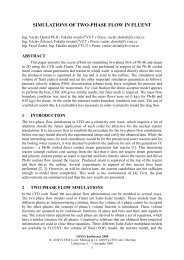
In developing an asphalt plant burner, CFD simulation shows<br />
velocity contours and pathlines indicating flow distribution around<br />
the fanwheel (top). Diffusive mixing of methane is indicated by<br />
pathlines around the gas injection pipe assembly (bottom).<br />
Images courtesy Astec Industries.<br />
More Time for Better Quality and<br />
Greater Innovation<br />
ANSYS structural analysis software is a core tool<br />
for the state-of-the-art development facility at the<br />
headquarters of Husky Injection Molding Systems Ltd.<br />
in Canada. The company designs and manufactures<br />
the plastics industry’s most comprehensive range of<br />
injection molding equipment, including machines,<br />
molds, hot runners and robots.<br />
In developing these large injection molding<br />
machines, engineers face demanding design<br />
challenges. Machine weight must be minimized to<br />
keep manufacturing and transportation costs low.<br />
Operating speeds must be fast enough for required<br />
throughput of manufactured plastic parts. Reliability<br />
and precision must be maintained to provide<br />
satisfactory service with minimal downtime. Efficiency<br />
www.ansys.com ANSYS <strong>Solutions</strong> | Volume 7, Issue 4 20<strong>06</strong>
Industry Spotlight<br />
10<br />
is a requirement to keep energy consumption low and<br />
thus minimize operating costs.<br />
Engineers at Husky met these challenges with<br />
ANSYS Workbench and ANSYS DesignSpace tools.<br />
The integrated solutions provided efficient contact<br />
representation for complex nonlinear assembly<br />
analysis, additional pre-analysis in construction<br />
and the benefit of common simulation methods in<br />
the various types of analyses. Engineers report<br />
that analyses formerly taking a week now can be<br />
completed in just half a day. This level of increased<br />
analysis efficiency is said to enable development<br />
teams to achieve better machine quality and greater<br />
innovation in products such as the company’s new<br />
Reflex platens.<br />
New Rotodynamics Capability Increases<br />
Analysis Productivity<br />
Design analysis of parts and assemblies in the<br />
industrial machinery industry involves complex<br />
computer-aided design (CAD) assemblies. To<br />
accurately handle these geometries in the design<br />
process, ANSYS offers close connection with CAD<br />
to access geometry and material parameters; it also<br />
allows quick turn-around while preparing geometry for<br />
analysis. Geometry creation and editing tools allow<br />
geometry manipulation for physics-based meshing<br />
and analysis.<br />
U.S.-based Trane, a business of American<br />
Standard, Inc. and a leading worldwide supplier of<br />
HVAC (heating, ventilating and air conditioning), uses<br />
ANSYS software to design rotating equipment in<br />
industrial chillers and air conditioning equipment using<br />
the new rotordynamics capability. The ability to import<br />
full 3-D CAD models into ANSYS Workbench allows<br />
the user to analyze accurate 3-D models instead of<br />
creating simplified 1-D representation of the geometry.<br />
Productivity tools such as automatic contact detection<br />
allow for easy problem setup and more time spent on<br />
engineering design decisions.<br />
To survive in the global economy of the third<br />
millennium, manufacturers need to be inventive in<br />
terms of factory equipment and raw materials, as well<br />
as with the processes they develop. Using simulationdriven<br />
design efforts can bring value and innovation to<br />
a wide range of product development applications. ■<br />
The author wishes to thank development, technical support<br />
and marketing personnel at ANSYS, Inc. for their efforts and<br />
contributions to this article.<br />
Trane uses ANSYS geometry (top), meshing (middle) and dynamics<br />
(bottom) solutions to design HVAC systems and comprehensive facility<br />
solutions for factories and other large commercial and industrials.<br />
Images courtesy Trane, a business of American Standard, Inc.<br />
www.ansys.com ANSYS <strong>Solutions</strong> | Volume 7, Issue 4 20<strong>06</strong>
11<br />
Image courtesy<br />
Sheffield University.<br />
ANSYS, Inc. Welcomes<br />
Fluent Inc.<br />
ANSYS broadens its opportunities to provide leading-edge<br />
engineering solutions with the acquisition of Fluent Inc.<br />
By Chris Reid<br />
Vice President, Marketing<br />
ANSYS, Inc.<br />
On May 1, 20<strong>06</strong>, ANSYS, Inc. announced the completion<br />
of the acquisition of Fluent Inc., headquartered in<br />
Lebanon, New Hampshire. Fluent is a global provider<br />
of computer-aided engineering (CAE) products that<br />
utilize computational fluid dynamics (CFD) principles<br />
and techniques to enable engineers and designers to<br />
simulate fluid flow, heat and mass transfer, and related<br />
phenomena involving turbulent, reacting and multiphase<br />
flow. This acquisition reaffirmed the ANSYS<br />
commitment to providing the open interface and<br />
flexible simulation solutions that customers require.<br />
What follows is some background information<br />
to help you get better acquainted with the newest<br />
member of the ANSYS family.<br />
History of Fluent Inc.<br />
In 1982, when CFD was primarily of interest to<br />
academic specialists, engineers at Creare, Inc., a New<br />
Hampshire consulting company, collaborated with<br />
researchers at Sheffield University in Sheffield, UK, to<br />
develop an interactive, easy-to-use CFD software<br />
product for engineers. Called FLUENT, the first version<br />
of this software was launched in October 1983. The<br />
product was so successful that, in 1990, the FLUENT<br />
group at Creare split from its parent company, moved<br />
to a new location and formed Fluent Inc.<br />
Rapid expansion of Fluent’s software business<br />
ensued, and, in May 1996, Fluent acquired Fluid<br />
Dynamics International, the developer of the<br />
general-purpose CFD software FIDAP. In 1997, Fluent<br />
acquired Polyflow S.A., the developer of POLYFLOW,<br />
a specialty CFD software product for the analysis of<br />
materials such as polymers, plastics, food and rubber.<br />
Since its inception, Fluent has continued to<br />
innovate and grow by offering superior CFD software<br />
and services to companies around the world.<br />
Industry-Leading Technology<br />
The broad physical modeling capabilities of FLUENT<br />
technology have been applied to industrial applications<br />
ranging from air flow over an aircraft wing to<br />
combustion in a furnace, from bubble columns to<br />
glass production, from blood flow to semiconductor<br />
manufacturing, from clean room design to wastewater<br />
treatment plants. The ability of the software to model<br />
reacting flows, aeroacoustics, turbulence, moving<br />
meshes and multiphase systems has served to broaden<br />
its reach. Today, thousands of companies throughout<br />
the world benefit from using FLUENT software.<br />
The suite of Fluent CFD products includes<br />
FLUENT, FIDAP and POLYFLOW for CFD analysis;<br />
FloWizard, a rapid flow modeling tool that allows<br />
www.ansys.com ANSYS <strong>Solutions</strong> | Volume 7, Issue 4 20<strong>06</strong>
12<br />
Engineers at Wenger Manufacturing gained better insight into<br />
the operation of a vertical cascade dryer (used to manufacture<br />
pet food) by utilizing CFD. The consulting team at Fluent was<br />
able to provide Wenger with an understanding of the existing<br />
dryer in order to improve their ability to market, specify, apply<br />
and service it. Improved dryers allow food processors to meet<br />
guaranteed levels of product components, decrease costs and<br />
avoid recycling of fine particles that may detract from product<br />
appearance and present a fire hazard. Detailed airflow and<br />
pressure distribution in various sections of the dryer would be<br />
impossible to obtain through physical testing and measurement<br />
— but were possible to simulate using FLUENT software.<br />
Image courtesy Wenger Mfg.<br />
design and process engineers to quickly and<br />
accurately validate their designs much earlier in the<br />
product development cycle; FLUENT for CATIA V5,<br />
which integrates Fluent’s rapid flow modeling<br />
technology into the CATIA V5 product lifecycle<br />
management (PLM) process; and FlowLab, a studentfriendly<br />
tool that uses the power of flow visualization<br />
through CFD to teach basic fluid mechanics principles<br />
in the engineering classroom. Fluent’s products also<br />
include the preprocessors GAMBIT, TGrid and<br />
G/Turbo. Application-focused products include Icepak<br />
to optimize thermal management of electronics<br />
designs; Airpak for modeling airflow, heat transfer,<br />
contaminant transport and thermal comfort for the<br />
built environment; and MixSim for the simulation of<br />
stirred tanks.<br />
Fluent always has taken pride in understanding<br />
customers’ strategic goals and helping them come<br />
to fruition through both software and services.<br />
The complete array of services available addresses<br />
the specific needs of organizations and supports<br />
those organizations in implementing advanced<br />
technology solutions. Services include consulting,<br />
training and technical support.<br />
Extensive Simulation Community<br />
With the acquisition of Fluent Inc., ANSYS is pleased<br />
to welcome Fluent software users to the world’s<br />
largest simulation community. As a supplier to 94 of<br />
the FORTUNE 100, ANSYS serves a wide range of<br />
industries. They all have benefited from using ANSYS<br />
software products and services — which continue to<br />
expand, both with the addition of new technologies<br />
developed via innovative research and development<br />
and by acquisition, such as in the case of Fluent.<br />
ANSYS now has one of the broadest ranges of<br />
CFD simulation technologies in the world. ANSYS<br />
believes that success relies on ensuring customers’<br />
satisfaction. As such, in addition to focusing on<br />
investment in product development, the company will<br />
continue to provide the best possible service and<br />
support through technical centers of excellence<br />
around the world.<br />
The addition of Fluent products to the ANSYS<br />
portfolio significantly enhances the combined company’s<br />
ability to provide world-leading simulation capabilities<br />
to customers, consistent with the ANSYS vision<br />
and strategy.<br />
Broad and Integrated <strong>Solutions</strong><br />
ANSYS continues to concentrate on providing<br />
customers with best-in-class CAE tools integrated in a<br />
flexible manner that will enable easy and rapid analysis<br />
and optimization of engineering designs.<br />
Clearly, there is now the opportunity for tighter<br />
linkages between ANSYS products, such as ANSYS<br />
In this example, FLUENT software is used to optimize<br />
the cooling package for a line of tractors. The cooling fan<br />
characteristics, along with the placement of underhood<br />
modules, are varied to achieve optimum performance.<br />
Courtesy Case New Holland.<br />
www.ansys.com ANSYS <strong>Solutions</strong> | Volume 7, Issue 4 20<strong>06</strong>
13<br />
CFD is becoming critical to the furnace design process, particularly as environmental regulations become more stringent. To help meet<br />
these regulations, John Zink Company selected FLUENT software to assist in modeling flames for a vertical cylindrical furnace used in<br />
an oil refinery. By using FLUENT, engineers were able to improve fuel mixing in order to decrease NOx production and maintain flame<br />
height within the desired parameters. CFD modeling provided a proposed solution (right) to reduce burner interactions that had caused<br />
increased flame height (left).<br />
Image courtesy John Zink Co.<br />
Mechanical or ANSYS Multiphysics, and Fluent<br />
products, as the company has done already with<br />
ANSYS CFX. The benefits of this strategy to<br />
customers and the engineering simulation industry<br />
have been real and measurable in terms of increased<br />
innovation, greater productivity and lower costs.<br />
ANSYS, Inc. fully expects to extend the same benefit<br />
to today’s Fluent user community.<br />
With the addition of more than 700 new<br />
employees from Fluent and its subsidiaries, the<br />
combined team with many years of simulation<br />
experience, deep industry expertise and world-class<br />
engineering talent will deliver even more exciting<br />
advances in integrated CAE. To support the ability<br />
to provide industry-leading advancements, ANSYS will<br />
continue its focus on innovation and target approximately<br />
20 percent of revenue to be spent on R&D.<br />
Moving Forward<br />
ANSYS and Fluent always have had much in<br />
common. Now, the goals each company had for<br />
the future are shared, and progress toward<br />
these goals can be accelerated and fulfilled to the<br />
benefit of customers. As in the past, ANSYS will<br />
maintain a strong commitment to employees, partners<br />
and customers as well as to the advancement of<br />
technology through innovation. ■<br />
Some of the world’s greatest soccer goalkeepers have been<br />
beaten by unusual swerving balls that move left then right<br />
before hitting the back of the net, even though they have little<br />
or no spin applied to them. A team of researchers led by<br />
Dr. Matt Carré at the Department of Mechanical Engineering,<br />
University of Sheffield used FLUENT to demonstrate that the<br />
shape, surface and asymmetry of the ball, as well as its initial<br />
orientation, have a profound effect on how the ball moves<br />
through the air after it is kicked. The image shows high-speed<br />
airflow pathlines colored by local velocity over the Adidas ®<br />
Teamgeist 20<strong>06</strong> soccer ball.<br />
Image courtesy Sheffield University.<br />
www.ansys.com ANSYS <strong>Solutions</strong> | Volume 7, Issue 4 20<strong>06</strong>
14<br />
The new sliding mesh capability in FLUENT 6.3<br />
allows for many sliding interfaces within a<br />
single simulation. In the case of the V22<br />
Osprey, the rotating propellers gradually tilt<br />
as the craft lands on a platform, changing<br />
the propulsion from forward to hover mode.<br />
FLUENT 6.3: Major Advances<br />
in CFD Simulation<br />
The latest addition to the ANSYS family features new solver,<br />
modeling and other options — resulting in greater speed and flexibility.<br />
By Christine Wolfe, FLUENT 6 Product Manager, Fluent Inc.<br />
Nicole Diana, Product Planning Manager, Fluent Inc.<br />
The current version of FLUENT software continues to<br />
evolve, allowing difficult engineering problems to be<br />
solved faster and with greater flexibility than<br />
ever before. The upcoming release of FLUENT 6.3<br />
offers innovative technology for addressing a broad<br />
range of applications. In all, there are more than 100<br />
new features that enhance core numerics and physical<br />
modeling capabilities in areas such as moving<br />
mesh, multiphase flow, combustion, reacting flow<br />
and radiation.<br />
New Solver Options<br />
In FLUENT 6.3, a pressure-based coupled solver joins<br />
the existing solver options. The new solver can<br />
improve solution efficiency as well as convergence and<br />
robustness for many cases. With this solver scheme,<br />
the pressure and velocity equations are solved in a fully<br />
coupled manner, while the other equations are solved<br />
sequentially. It is particularly beneficial for “stiff” problems<br />
and for solving problems on unusually skewed<br />
and stretched meshes.<br />
In addition, existing FLUENT solvers have been<br />
enhanced to offer improved robustness, accuracy<br />
and efficiency. For example, strong shocks can be<br />
captured more effectively with the density-based<br />
solver, and transient simulations can be run more<br />
efficiently with the pressure-based solver. Furthermore,<br />
a new diagnostic case check algorithm can be used to<br />
assess case settings and offer recommendations to<br />
ensure that commonly accepted best practices are<br />
being used.<br />
Polyhedral meshes are being introduced in<br />
FLUENT 6.3. These meshes allow the flexibility of an<br />
unstructured mesh to be applied to a complex<br />
geometry without the overhead associated with a<br />
large tetrahedral mesh. The polyhedral meshes are<br />
created using automatic cell agglomeration to<br />
combine tetrahedral cells into polyhedral ones. This<br />
can reduce the overall cell count by a factor of 3 to 5.<br />
The automatic nature of these mesh agglomeration<br />
techniques saves the user time and, since the polyhedral<br />
mesh contains as few as one-fifth the number<br />
of cells in the original tetrahedral mesh, convergence<br />
is faster.<br />
In support of FLUENT software’s ongoing<br />
commitment to parallel processing, numerous<br />
improvements to parallel efficiency and flexibility have<br />
In FLUENT 6.3, a discrete phase<br />
of particles, droplets or bubbles<br />
can be launched from a surface<br />
at normal angles, as is shown<br />
for a Rushton impeller in a<br />
stirred tank.<br />
www.ansys.com ANSYS <strong>Solutions</strong> | Volume 7, Issue 4 20<strong>06</strong>
Nylon is injected into a mold in this simulation of the production of a plastic<br />
gear part. The plastic has non-Newtonian rheology, and the ratio of the nylon to<br />
air viscosities is very large. To address this complex free surface flow, a new<br />
interface tracking scheme in FLUENT 6.3 is used.<br />
been implemented along with speed improvements for<br />
reading and writing case and data files. High-performance<br />
computing also benefits from a 64-bit Windows<br />
version of FLUENT 6.3.<br />
New Modeling Options<br />
New models and extensions to existing models add to<br />
the technology’s capabilities in the areas of moving<br />
mesh, reacting flow, multiphase flow and radiation.<br />
FLUENT software’s industry-leading dynamic<br />
mesh capability for modeling moving objects — such<br />
as pistons and valves in IC engines, store, separation<br />
and impellers in baffled mixing tanks — has been<br />
enhanced. In FLUENT 6.3, the dynamic mesh<br />
capability can be applied to a series of related steadystate<br />
simulations, making them easier for users to set<br />
up and perform. For example, a control valve can be<br />
simulated with a range of open positions by building<br />
only one mesh and having FLUENT software rebuild<br />
the mesh for each new position. Other improvements<br />
make problem setup and user-defined mesh motion<br />
even more straightforward and efficient.<br />
In some cases, the motion of objects can be<br />
captured by using regions of mesh that slide along<br />
a common interface. This technique is useful for<br />
modeling two trains passing in a tunnel, for example.<br />
FLUENT 6.3 now is able to model more complex<br />
object motion by allowing for multiple sliding mesh<br />
regions on one side of an interface to be paired with<br />
multiple sliding regions on the opposite side.<br />
Reacting flow simulations benefit from new slow<br />
chemistry and micromixing models, useful for liquid<br />
reactions and certain combustion applications. A<br />
larger number of chemical species and reactions can<br />
be handled in the non-premixed and partially premixed<br />
combustion models. Emissions modeling is more<br />
comprehensive through the addition of SOx prediction<br />
and the selective noncatalytic reduction of NOx<br />
through urea injection. Expanded in-cylinder combustion<br />
capabilities include the ability to model ignition<br />
delay in stratified engines.<br />
Multiphase modeling continues to be an area<br />
of focus for FLUENT 6 development, and major<br />
improvements can be found in the accuracy of<br />
transient multiphase solutions. For the Eulerian multiphase<br />
model, enhancements extend the regimes for<br />
which this model can be applied. For example, both<br />
compressible gas and liquid phases can be present,<br />
and the mixing plane model can be used, simplifying<br />
the solution of multiphase flows in pumps. For free<br />
surface flows simulated using the volume of fluid (VOF)<br />
model, a new interface tracking scheme is available<br />
that improves solution stability when the viscosity ratio<br />
between the phases is high. FLUENT 6.3 technology<br />
also allows a user-defined function (UDF) to be utilized<br />
to specify the wall contact angle, allowing a dynamic<br />
value to be calculated from the local flow field. This<br />
feature is of primary importance for capillary-driven<br />
flows in which surface tension is important.<br />
For simulations involving surface-to-surface<br />
radiation, extensions to the existing model make the<br />
problem definition easier, and increase the solution<br />
efficiency and range of applicability. For example, this<br />
technique now can be used for 2-D axisymmetric<br />
cases, and the participating boundaries can be<br />
specified more easily in the graphical user interface.<br />
Add-On Modules and Third-Party Tools<br />
Several capabilities can be added to FLUENT software<br />
through add-on modules. A population balance<br />
module is new with FLUENT 6.3. This module makes<br />
it possible to model multiphase flows with a particle<br />
or droplet size distribution. Three approaches are<br />
available that account for breakup and agglomeration<br />
so that applications such as bubble columns and<br />
crystallizers can be modeled. The proton-exchange<br />
membrane (PEM) and solid-oxide fuel cell (SOFC)<br />
modules have been enhanced in FLUENT 6.3.<br />
For PEM fuel cells, transient simulations can be<br />
performed and electrical conductivity can be obtained<br />
from the FLUENT materials database. For the SOFC<br />
module, the range of conditions that can be simulated<br />
has increased.<br />
Another improvement in FLUENT 6.3 is the ability<br />
to work with third-party CAE packages. It is now<br />
easier to import and export files to and from other<br />
analysis tools (for fluid structure interaction, for<br />
example) and postprocessing tools (such as EnSight<br />
or Fieldview, for example).<br />
Along with many other features, these highlights<br />
make FLUENT 6.3 software a major step forward in<br />
commercial CFD capability. ■<br />
The ability to solve on polyhedral meshes is<br />
new in FLUENT 6.3. Tetrahedral cells are<br />
agglomerated to form polyhedra in the solver,<br />
resulting in a reduced overall cell count that<br />
requires less CPU time to reach convergence.<br />
15<br />
www.ansys.com ANSYS <strong>Solutions</strong> | Volume 7, Issue 4 20<strong>06</strong>
16<br />
Analyzing Composites<br />
for Satellite Components<br />
Researchers used ANSYS technology to study the behavior of a<br />
composite housing for electronic circuits and quickly developed a<br />
design nearly 30 percent lighter than a comparable aluminum structure.<br />
By Harri Katajisto<br />
R&D Engineer<br />
Componeering Inc.<br />
Helsinki, Finland<br />
Scientific, observation and reconnaissance missions<br />
often are performed by low-orbiting micro-satellites.<br />
These systems are much smaller and more compact<br />
than larger telecommunications satellites, so space<br />
is severely limited and heat is more difficult to<br />
dissipate from closely packed electronic components.<br />
Traditionally, satellite electronics housings are made of<br />
aluminum. This material is lightweight, has adequate<br />
heat dissipation and provides good protection against<br />
ambient spatial radiation.<br />
In one recent study, the European Space Agency<br />
(ESA) investigated the feasibility of fabricating these<br />
housings of composites to determine if this type<br />
of material systems could provide the same heat<br />
dissipation as aluminum but with less mass. In this<br />
study, Verhaert Design and Development in Belgium<br />
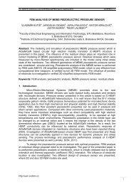
Figure 1. The Proba 2 micro-satellite has instruments to<br />
make solar observations and space weather measurements.<br />
The electronics housing from this micro-satellite<br />
was used as a reference application in the ESA study.<br />
Image courtesy Verhaert Design and Development.<br />
www.ansys.com ANSYS <strong>Solutions</strong> | Volume 7, Issue 4 20<strong>06</strong>
Figure 2. The housing with its back panel removed shows<br />
composite laminate structures together with aluminum<br />
wedge locks and mounting rails.<br />
Photo courtesy LLS/HUT.<br />
provided the reference application for the study: the<br />
Advanced Data and Power Management System<br />
(ADPMS) aluminum housing for the Proba 2 microsatellite<br />
in Figure 1. Analysis of the composite housing<br />
was performed by Componeering Inc., which specializes<br />
in simulation and design of high-performance composite<br />
structures. The Laboratory of Lightweight<br />
Structures at Helsinki University of Technology<br />
was responsible for the design, prototyping and<br />
manufacturing of the housing, shown in Figure 2.<br />
The Challenge of Designing with<br />
Composites<br />
Designing composite structures with sandwich-type<br />
elements or layered solid laminates is very challenging<br />
due to the anisotropic behavior of the material.<br />
Moreover, the design depends on multiple variables<br />
such as material selection, number of layers, layer<br />
orientations and stacking sequence.<br />
In the structure under investigation, performance<br />
requirements for the composite housing were derived<br />
from the requirements of the aluminum housing.<br />
For example, the goal in radiation protection was<br />
to provide shielding against spatial radiation in low<br />
earth orbit comparable to the aluminum design with a<br />
2mm wall thickness. This was achieved by embedding<br />
tungsten foil inside the carbon fiber-reinforced<br />
plastic (CFRP) laminate structure of the housing<br />
external panels.<br />
One important requirement was that mechanical<br />
interfaces of the composite housing had to be<br />
identical to the aluminum counterpart. Inside and<br />
outside contours of the housing had to accommodate<br />
internal circuit boards and connectors as well as<br />
external components of the satellite. These constraints<br />
limited the composite design, in which smooth shapes<br />
are preferable.<br />
To provide thermal management comparable<br />
to the aluminum housing, heat dissipation for the<br />
composite structure was provided by layers of<br />
plastic reinforced with K1100 pitch-based carbon<br />
fibers. Combined with the plastic matrix as a ply<br />
configuration, these fibers yield about four times<br />
higher thermal conductivity in the direction of fibers<br />
than typical aluminum alloys. Moreover, the natural<br />
black color of CFRP provides high emissivity, and heat<br />
is dissipated very efficiently from the surface. From a<br />
structural standpoint, however, the K1100 fibers<br />
exhibit very low failure strain and break easily when<br />
bent on a small radius.<br />
Compounding the design challenge, mismatches<br />
in coefficients of thermal expansion (CTE) between the<br />
composite housing and aluminum wedge locks and<br />
satellite support structures cause deformations when<br />
the structure is subjected to temperature change.<br />
Because of these complexities, determining<br />
thermal balance, structural integrity and resonant<br />
frequencies of the housing using conventional analysis<br />
methods can be an extremely cumbersome task.<br />
Results would most likely have a high probability of<br />
error due to simplifications that would not adequately<br />
account for all design variables.<br />
Advanced Tools for Simulation and Design<br />
To meet these challenges, we performed a wide range<br />
of analyses using ANSYS Mechanical software<br />
throughout the project. During conceptual design,<br />
laminate through-the-thickness direction behavior was<br />
studied with a solid thermal model using SOLID70<br />
elements as shown in Figure 3. (See next <strong>page</strong>.)<br />
Analysis results demonstrated that single-layer<br />
elements are adequately representative for thin<br />
laminates in steady state, so only in-plane thermal<br />
conduction capability of the SHELL131 element was<br />
used. The effective conductivities of the laminate were<br />
verified easily with capabilities of SHELL131 and<br />
simple test models. Mechanical interfaces and<br />
adhesively bonded joints were modeled using<br />
thermal LINK33 elements, with contact resistance<br />
depending on joint materials, surface roughness and<br />
contact pressure. Input data definition for thermal links<br />
17<br />
www.ansys.com ANSYS <strong>Solutions</strong> | Volume 7, Issue 4 20<strong>06</strong>
18<br />
Figure 3. Representative 3-D model illustrates temperature<br />
variation in the laminate through-the-thickness direction (left)<br />
and high thermal flux in the two K1100 layers located on<br />
both surfaces (right).<br />
was based on a literature study. Both conduction<br />
and radiation heat transfer modes were considered.<br />
The radiation effect was applied using the SURF151<br />
element that was overlaid onto the SHELL131<br />
element.<br />
Thermal analysis of this type is readily performed<br />
in ANSYS software, which provides the capability to<br />
use nodal temperatures resolved from the thermal<br />
model as an input for the structural model. The use of<br />
this feature is very simple, since ANSYS internally<br />
converts the thermal results file *.rth to equivalent<br />
force and moment vectors in the structural model.<br />
In this study, in-service temperature variations in<br />
laminate structures were quite small, so thermal<br />
bending was not an important factor. However, thermal<br />
bending was found critical in some manufacturing test<br />
trials in which laminate structures were bonded at high<br />
temperature with aluminum wedge locks. For these<br />
cases, SHELL181 has proved to give excellent results,<br />
providing ease of controlling the laminate crosssection<br />
input data.<br />
The wedge locks do not fully cover the hat<br />
section in the depth direction, and ANSYS thermal<br />
analysis revealed that part of the heat-dissipation<br />
capacity was lost with K1100 layers oriented in the<br />
longitudinal direction of the housing, as shown in<br />
Figure 4. It was found that when K1100 layers were<br />
oriented in ±30 degrees, the temperature distribution<br />
was more homogenized, the peak temperature was<br />
the same and, structurally, the lay-up was acceptable.<br />
The stiffness requirements of the housing<br />
dictated the number of required structural M<strong>40</strong>J CFRP<br />
layers. The orientation and stacking sequence of both<br />
K1100 and M<strong>40</strong>J layers was based on the laminate<br />
stiffness and CTE. CFRP structures have slightly<br />
negative CTE in the fiber direction. Respectively, in<br />
the perpendicular direction to the fibers, CTE is in<br />
the magnitude of aluminum. The wedge locks were<br />
adhesively bonded to the laminate structures<br />
and acted like stiffeners. Due to this bonding<br />
and orientation, the CTE of the laminate was an<br />
important design parameter.<br />
The laminate design was performed using<br />
ESAComp software (www.esacomp.com), which is a<br />
dedicated tool for preliminary and detailed analysis of<br />
composite structures. ESAComp interfaces smoothly<br />
with ANSYS software. Laminate lay-ups and material<br />
data can be exported to ANSYS for composite solid<br />
and shell elements. Moreover, FEA results from<br />
ANSYS can be imported to ESAComp for detailed<br />
post-processing. This capability was used, for example,<br />
in studying the criticality of the laminate interlaminar<br />
shear (ILS) stresses, which became high close to the<br />
inserts that were used to attach different panels.<br />
Creating simulation models was facilitated using<br />
ANSYS Parametric Design Language (APDL), which<br />
could be linked to ESAComp for optimizing the<br />
design. With APDL, an external software such as<br />
ESAComp can be readily linked to the design cycle,<br />
thus allowing simulation to effectively guide the<br />
development process toward the best design.<br />
After completion of the thermal analysis with<br />
ANSYS software and laminate design with ESAComp,<br />
ANSYS Mechanical was used for structural analysis of<br />
the housing, including a modal analysis for natural<br />
Figure 4. ANSYS thermal analysis of the composite hat section<br />
revealed that heat-dissipation capacity varied according to<br />
the orientation of the K1100 layers of the laminate.<br />
www.ansys.com ANSYS <strong>Solutions</strong> | Volume 7, Issue 4 20<strong>06</strong>
Figure 5. The same ANSYS model was used for both structural<br />
and thermal analysis in determining characteristics such as<br />
the thermal balance of the laminate structures and mode<br />
shapes of the system.<br />
frequencies up to 800 Hz. Modal analysis results<br />
together with the random vibration input specification<br />
defined the acceleration levels for the subsequent<br />
failure analysis. The design was predicted to withstand<br />
load levels multiplied by factor of safety of two,<br />
which is a typical value for composite materials in<br />
space applications.<br />
In the ANSYS model for these structural studies,<br />
the quadratic composite SHELL99 element was<br />
used for meshing the laminate structures. SHELL99 is<br />
applicable to thin laminates, but it contains transverse<br />
shear deformations capability as well. Bolted joints<br />
and inserts were modeled using the BEAM4 element<br />
in order to be able to extract laminate bearing stresses<br />
and insert pull-out forces.<br />
Impact and Benefits of the Solution<br />
Thermal tests performed in the vacuum chamber at<br />
the European Space Research and Technology Centre<br />
(ESTEC) in the Netherlands corresponding to the<br />
worst hot temperature condition of the equipment<br />
confirmed that simulation accurately predicted<br />
the satisfactory heat-dissipation capacity of the<br />
composite housing.<br />
Using an electromagnetic shaker, sine and<br />
random vibration tests of a breadboard model were<br />
conducted at the Royal Military Academy in Brussels,<br />
Belgium. The composite housing was found stiffer<br />
than its aluminum counterpart, and overall behavior of<br />
the system was as predicted with simulations.<br />
In this project, ANSYS software worked smoothly<br />
in exchanging data with ESAComp. Time was saved in<br />
generating simulation models by importing required<br />
data directly from ESAComp into ANSYS, as well as<br />
taking advantage of automated features of ANSYS<br />
contact elements and power of APDL for parameterization.<br />
Considerable time also was saved through the<br />
ability to use the same ANSYS model for both<br />
structural and thermal analyses, as shown in Figure 5.<br />
In the course of the project, details of the composite<br />
structure were studied with simulation before going<br />
through the time and expense of building physical<br />
prototype breadboard models. In this way, the<br />
modified structure could be analyzed and feedback<br />
provided almost instantly to the design team.<br />
The ability of ANSYS software to work well with<br />
ESAComp, to provide a robust parametric model<br />
representing all the different components and to<br />
reliably perform both structural and thermal analyses<br />
was key to the speed and accuracy in successfully<br />
completing the study. With the help of this level of<br />
advanced analysis, the behavior of the structure could<br />
be properly understood, the design of the composite<br />
housing was optimized to provide a mass saving of<br />
29 percent over a comparable aluminum housing and<br />
the project was completed in only 18 months from the<br />
kick-off meeting to the final presentation of results. ■<br />
Refer to the following papers for more information on<br />
this project:<br />
Katajisto, H. et al., “Structural and Thermal Analysis of<br />
Carbon Composite Electronics Housing for a Satellite,”<br />
Conference Proceedings of the 1st NAFEMS Nordic<br />
Seminar “Component and System Analysis Using Numerical<br />
Simulation Techniques — FEA, CFD, MBS,” Gothenburg,<br />
November 23-24, 2005.<br />
Brander, T. et al., “CFRP Electronics Housing for a Satellite,”<br />
Proceedings of European Conference on Spacecraft<br />
Structures, Materials and Mechanical Testing, Noordwijk,<br />
May 10-12, 2005.<br />
Jussila, J. et al., “Manufacture and Assembly of CFRP<br />
Electronics Housing,” Proceedings of European Conference<br />
on Spacecraft Structures, Materials and Mechanical Testing,<br />
Noordwijk, May 10-12, 2005.<br />
19<br />
www.ansys.com ANSYS <strong>Solutions</strong> | Volume 7, Issue 4 20<strong>06</strong>
Visualization of the turbine velocity vectors<br />
at the blade mid-span location<br />
20<br />
CFD Simulation Brings Electrical<br />
Power to Rural Areas<br />
ANSYS CFX software improves the design and efficiency of a small<br />
hydro-generator for use in remote areas of developing countries.<br />
By Robert Simpson, Ph.D.<br />
Nottingham Trent University, UK<br />
In developing countries, many remote rural communities<br />
do not have access to electricity due to the large<br />
expenses associated with extension of the national<br />
grid. Where these communities have access to a<br />
suitable site, small hydroelectric schemes are found to<br />
be a cost-effective and sustainable means of providing<br />
electricity. The Micro Hydro Research Centre at<br />
Nottingham Trent University has been carrying<br />
out research into small-scale standardized hydrogenerator<br />
units that are directly affordable for villagers<br />
in developing countries.<br />
Low-head hydro sites (2 to 10m) offer the<br />
potential for providing electricity to many communities,<br />
but progress has been hampered by the lack of an<br />
appropriate turbine design. A research project has<br />
been undertaken in collaboration with Practical Action<br />
Peru (formerly known as Intermediate Technology<br />
Development Group) to develop a standard design<br />
procedure for the cost-effective local manufacture<br />
of pico-propeller turbines with good performance<br />
and reliability. Pico-hydro is the smallest classification<br />
of power output with a maximum output of 5kW.<br />
Fixed geometry propeller turbines are one of the<br />
most cost-effective turbine options for low-head<br />
pico-hydropower.<br />
The first objective of the project was to design<br />
a simplified prototype turbine based on current<br />
knowledge and to have it manufactured and installed<br />
at a field site in Peru. Stage two involved analyzing<br />
the turbine using computational fluid dynamics (CFD)<br />
www.ansys.com ANSYS <strong>Solutions</strong> | Volume 7, Issue 4 20<strong>06</strong>
to improve the design and efficiency. Using CFD<br />
provides the flexibility to make design changes,<br />
investigate scale effects and vary the hydrological<br />
conditions (head and flow rate) without the need and<br />
expense of creating a prototype for each test case.<br />
ANSYS CFX software was used for all aspects<br />
of the CFD study because of its good track record<br />
with turbomachinery analysis and because it is<br />
part of an integrated system of software, which<br />
includes CFX-BladeGen (now ANSYS BladeModeler)<br />
and ANSYS TurboGrid for design and analysis of<br />
bladed geometry.<br />
21<br />
Prototype Turbine in Peru<br />
The prototype turbine for the project is located on a<br />
small farm in the northern highlands of Peru. Currently,<br />
the turbine is producing electricity for the owner’s<br />
farmhouse located several hundred meters away, and<br />
the horizontal shaft layout was designed to facilitate<br />
easy connection to existing mechanical equipment<br />
used by the farmer to produce feed for several chicken<br />
farms. Water for the turbine is diverted into a concrete<br />
channel from an existing irrigation channel that runs<br />
across the plot of land.<br />
The spiral casing has a simplified design with<br />
a tapered rectangular cross-section. The rotor<br />
blades were manufactured using flat sheet metal<br />
bent and twisted into the required shape. Preliminary<br />
field testing of the turbine revealed several problems<br />
during operation. Water was being emptied from<br />
the forebay tank, resulting in a much lower head than<br />
the available four meters, and the turbine was not<br />
producing sufficient power to get the generator up<br />
to operating voltage.<br />
Simulation Helps Refine the Design<br />
Simulations performed on the original rotor geometry<br />
showed that the maximum turbine efficiency was<br />
predicted to be approximately 55 percent at 600 rpm<br />
with a flow rate of 284 liters per second (l/s). However,<br />
available flow rate at the site was measured to be in<br />
the range of 180–220 l/s, which was not enough flow<br />
for the turbine to operate efficiently. From this<br />
preliminary study, it was concluded that the blade<br />
angles for the original rotor were incorrect. A new rotor<br />
with flatter blades and a higher solidity ratio was<br />
designed using conventional theoretical methods. The<br />
new rotor geometry was analyzed using ANSYS CFX<br />
software, and the results predicted a significant reduction<br />
in the flow rate required to obtain the same power<br />
output. In addition, the power curve demonstrated an<br />
improved performance over the speed range with a<br />
predicted best efficiency for the new rotor of 80<br />
percent at 800 rpm.<br />
This project was undertaken to provide power to a farmhouse<br />
in rural Peru that is used to grind feed for several chicken<br />
farms owned by the farmer.<br />
The civil works required for power generation consisted of a<br />
concrete channel, silt basin, forebay tank and the powerhouse.<br />
The turbine drives an induction motor as generator (IMAG)<br />
with controller. The radiator-type ballast loads can be seen<br />
glowing red in the picture (upper left).<br />
www.ansys.com ANSYS <strong>Solutions</strong> | Volume 7, Issue 4 20<strong>06</strong>
22<br />
Preliminary CFD simulations were used to compare the<br />
original and redesigned rotor geometry. A total pressure<br />
boundary condition was used for the inlet to simulate a<br />
constant head of four meters.<br />
The revised CFD simulations for the redesigned rotor show<br />
reasonable agreement with the field tests for power output.<br />
The new rotor was fabricated by a local manufacturer<br />
in Peru, and field test data was obtained.<br />
A revised and more accurate CFD model also was<br />
created, which took into account parameters and<br />
geometry changes that were not included in the<br />
preliminary simulations.<br />
The revised CFD simulations had reasonable<br />
agreement with the field test results for the power<br />
output in the low-speed range. However, in the<br />
high-speed range (above 1200 rpm), the results tend<br />
to overpredict the power output when compared<br />
to the field tests. The flow rate through the turbine<br />
also is underpredicted by the CFD simulations by<br />
approximately 10 precent. Further investigation is<br />
currently under way to determine the effect of changes<br />
to the ANSYS CFX model, including roughness<br />
effects, leakage losses through the hydrodynamic<br />
seal and cavitation modeling.<br />
The new rotor was manufactured locally using flat sheet<br />
metal bent and twisted into shape and welded to the hub.<br />
Ongoing Research<br />
ANSYS CFX software has been used successfully to<br />
analyze and identify an operational problem with the<br />
original prototype turbine for the project. Furthermore,<br />
the software has proved to be a valuable design tool in<br />
the process of developing and analyzing possible new<br />
rotor geometries for the turbine. At the time of writing,<br />
the turbine was producing approximately 4kW of electrical<br />
power on site at a turbine efficiency of 65 percent.<br />
Ongoing research aims to further improve the turbine<br />
design and complement the existing CFD and<br />
field-test results with detailed laboratory testing. ■<br />
This project is funded by a research grant awarded by<br />
the Leverhulme Trust to Arthur Williams, Ph.D. (principal<br />
investigator) and Shirley Ashforth-Frost, Ph.D., Nottingham<br />
Trent University, UK.<br />
For further information, contact Robert Simpson<br />
(robert.simpson@ntu.ac.uk) or Arthur Williams<br />
(arthur.williams@ntu.ac.uk) of Nottingham Trent University.<br />
Visualization of the velocity vectors at the<br />
blade mid-span The location fluid volume for the ANSYS CFX simulation was<br />
separated into four domains: the spiral casing, guide<br />
vanes, rotor passage and draft tube.<br />
www.ansys.com ANSYS <strong>Solutions</strong> | Volume 7, Issue 4 20<strong>06</strong>
Guest Commentary<br />
Integrating CAD and CAE to<br />
Enable Simulation-Driven Design<br />
23<br />
Lack of knowledge capture and re-use holds<br />
many companies back from gaining the full<br />
benefits of analysis.<br />
By Don Brown, Chairman<br />
Collaborative Product Development<br />
Associates, U.S.A.<br />
The explosion of computational<br />
capacity, now at rock bottom<br />
prices, will turn engineering<br />
simulation into an everyday<br />
tool for all engineers and<br />
designers across the full<br />
product development process.<br />
In such a paradigm shift, CAE<br />
begins up front with conceptual<br />
design, engineers perform<br />
much of their own simulation<br />
and analytical results drive<br />
design decisions. Simulation<br />
experts determine the right process, analysis assumptions<br />
and check-points to validate results — but do<br />
not directly execute analysis work.<br />
What’s holding us back from integrating CAD<br />
and CAE to enable simulation-driven design?<br />
Our Design/Simulation Council addresses these<br />
challenges with a proposed standard framework<br />
to integrate and optimize the divergent specialist<br />
activities that fragment design and simulation. A core<br />
problem relates to lack of knowledge capture and<br />
re-use regarding simulation.<br />
Some forward-thinking companies are making<br />
significant headway in leveraging the knowledge of<br />
expert specialists in their simulation-driven design<br />
efforts. Several initiatives rely on an abstract model<br />
representing analysis work that can be performed<br />
across similar parts, at all stages of product development<br />
and across all analysis domains. The model<br />
includes three main types of information:<br />
■ Input for the early concept phase covering<br />
performance requirements and functional<br />
specifications<br />
■ Company rules and practices, product<br />
identification, context of the analysis and<br />
engineering knowledge or constraints<br />
that apply<br />
■ Analysis-related information as a function<br />
of part and product type that includes<br />
the part or system definition, geometry,<br />
assumptions, loads, boundary conditions<br />
and materials data<br />
The abstract model is used as a basis for creating a<br />
specific physical model for analysis. Mesh generation<br />
and formatting then translate the physical model into an<br />
analysis execution model for a particular solver.<br />
Broad implementation of such approaches<br />
involves a transformation for product development.<br />
Considerable data management is required to store<br />
expert knowledge and data models. CAE solutions<br />
must be architected to leverage this knowledge. Most<br />
important, organizational changes must meet the needs<br />
for cross-functional collaboration to integrate design<br />
and analysis.<br />
Leading-edge companies, including Airbus,<br />
Visteon, Whirlpool and John Deere, successfully utilize<br />
such an approach. At Visteon, the abstract model drives<br />
all automotive air-handling systems across both<br />
CAD and CAE. The abstract model is defined by 15<br />
components, 12 classes and <strong>40</strong> attributes. Airbus<br />
is standardizing structural analysis across all sites and<br />
disciplines by automatically generating data needed for<br />
a particular analysis code from a CAE data model that<br />
contains analysis abstract models, rules, relationships<br />
and other information. For example, the shape and<br />
dimension of each rib in a wing can be defined from a<br />
set of design rules and constraints, and models may<br />
apply to all frames of all aircraft based on particular<br />
plane geometry, loading conditions and materials.<br />
Today, as in the past, simulation technology too<br />
often is used only as a forensic tool for post-mortem<br />
checks, validation and troubleshooting after the fact,<br />
when the worst of the damage already has been done.<br />
Too many critical product development decisions are<br />
made based on assumptions and guesses rather than<br />
on engineering analysis, even though the tools are<br />
readily available. Simulation should be applied up front<br />
to avoid problems in the first place. ■<br />
Collaborative Product Development Associates<br />
(www.cpd-associates.com) provides in-depth information<br />
for assessing technology, business goals and<br />
implementation road maps for engineering and<br />
manufacturing. The firm hosts a variety of events and<br />
engages in programs for critical analysis of decision<br />
trade-offs regarding design creation and validation,<br />
design/simulation council, PLM integration/product<br />
definition and product value management.<br />
www.ansys.com ANSYS <strong>Solutions</strong> | Volume 7, Issue 4 20<strong>06</strong>
Simulation at Work<br />
24<br />
From the collection of<br />
Jean-Pierre Lauwers.<br />
CFD Simulation Recreates<br />
Aviation History<br />
Researchers used ANSYS CFX software to study the 19<strong>06</strong> flight<br />
of Alberto Santos-Dumont’s wood and silk aircraft, credited as<br />
the first officially recognized heavier-than-air flight in Europe.<br />
By Leonardo O. Bitencourt, Aeronautical Engineering, ESSS, Florianópolis, Brazil<br />
Ramon Morais de Freitas, Instituto Nacional de Pesquisas Espaciais<br />
Grégori Pogorzelski, Aeronautical Engineering, Instituto Tecnológico de Aeronautica<br />
João L. F. Azevedo, Senior Researcher, Instituto de Aeronáutica e Espaço<br />
Aviation pioneer Alberto Santos-Dumont<br />
From the collection of Jean-Pierre Lauwers.<br />
A native of Brazil, Alberto Santos-Dumont was a<br />
genius obsessed with the concept of flight. A hundred<br />
years ago, he designed and built a plane from pine<br />
and bamboo poles covered with Japanese silk in<br />
a complex biplane, boxkite-like configuration. For<br />
flight testing, he attached the aircraft to his latest<br />
dirigible, the Number 14, and the plane became<br />
known thereafter as the 14-Bis.<br />
On October 23, 19<strong>06</strong>, at the Bagatelli Field in<br />
Paris, Santos-Dumont flew his aircraft 200 feet and<br />
won the coveted Deutsch-Archdeacon Prize, which<br />
was created to encourage the growth of aviation. The<br />
flight was witnessed by officials from what would<br />
become the Federation Aeronautique Internationale,<br />
and Santos-Dumont was credited with making the first<br />
heavier-than-air powered flight in Europe.<br />
www.ansys.com ANSYS <strong>Solutions</strong> | Volume 7, Issue 4 20<strong>06</strong>
25<br />
Geometry of the 14-Bis<br />
Meshing the 14-Bis using ANSYS ICEM CFD software<br />
To commemorate this milestone in the history of<br />
aviation, a group of students in Brazil, assisted by<br />
Engineering Simulation and Scientific Software (ESSS,<br />
the ANSYS distributor in South America), established<br />
the CFD 14-Bis Project to celebrate the historic<br />
occasion through advanced computational fluid<br />
dynamics techniques. ANSYS CFX software was<br />
chosen to analyze and understand airflow around<br />
the plane’s surface.<br />
A CAD model was developed using historic<br />
pictures, plans and discussion. Due to the model’s<br />
complex geometry, the students meshed surfaces<br />
using hexahedral elements and represented volumes<br />
with a tetra/prism mesh. ANSYS ICEM CFD software<br />
was used to create both high-quality surface and<br />
volumetric meshes.<br />
Some conclusions can be drawn from the<br />
ANSYS CFX results. In his first attempt, Santos-<br />
Dumont used 24 hp nominal power and failed. In the<br />
second and successful attempt, he increased the<br />
nominal power to 50 hp. By analyzing drag and lift as<br />
well as engine thrust, the possible angle-of-attack and<br />
flight speed values could be estimated: Approximately<br />
five degrees and the range of 12 to 14 m/s are<br />
the predicted flight conditions. These values are<br />
higher than the speed of 11 m/s normally quoted<br />
in describing the flight.<br />
As this value is a ground-related speed, the<br />
possible discrepancy could be due to the presence of<br />
wind or ground effects during the centennial flight.<br />
This last factor currently is being studied. Aspects<br />
related to aircraft stability still are under investigation,<br />
but preliminary results indicate that the airplane was<br />
stable even though small variations in the center-ofgravity<br />
position could make the airplane dangerously<br />
approach unstable behavior. The simulation gave<br />
researchers insight into the airflow and dynamics of<br />
the plane as well as the genius and daring of the<br />
aviation pioneer Alberto Santos-Dumont. <br />
The authors wish to thank Professor Paulo Greco from Escola<br />
de Engenharia de São Carlos, Universidade de São Paulo,<br />
who provided the geometrical CAD model, and Marcus Reis<br />
from ESSS, who provided support and licenses for all the<br />
software used.<br />
Flow visualization using streamlines<br />
Lift dependence with flight velocity<br />
Qualitative analysis of velocity<br />
www.ansys.com ANSYS <strong>Solutions</strong> | Volume 7, Issue 4 20<strong>06</strong>
Simulation at Work<br />
26<br />
Weight-Optimized Design<br />
of a Commercial Truck Front<br />
Suspension Component<br />
Engineers at Dana Corporation use topology optimization features<br />
of ANSYS Mechanical software to reduce upper control arm weight<br />
by 25 percent while maintaining required stiffness and strength.<br />
Headquartered in Toledo, Ohio, Dana Corporation is<br />
a leading supplier of parts and assemblies to the<br />
automotive industry. The company designs and<br />
manufactures a wide range of products for every<br />
major vehicle producer in the world and has twice<br />
received the Malcolm Baldrige National Quality<br />
Award, which recognizes U.S. businesses that<br />
demonstrate outstanding quality and performance.<br />
Dana is focused on being an essential partner to<br />
automotive, commercial and off-highway vehicle<br />
companies, which collectively produce more than<br />
60 million vehicles annually.<br />
Dana’s Commercial Vehicle Systems Group<br />
specializes in development of front-steer, rear-drive,<br />
trailer and auxiliary axles; driveshafts; steering shafts;<br />
suspensions; and related systems, modules and<br />
services for the world’s commercial vehicle market.<br />
Dating back to the company’s beginnings in 1904,<br />
Dana products have helped drive history’s greatest<br />
vehicles, from the Model T and World War II-era army<br />
vehicles to London taxicabs, 18-wheel rigs, giant<br />
earth-moving machines and cars on the NASCAR<br />
racing circuit. Building on this foundation of<br />
Designed by Dana Corporation for<br />
commercial vehicles, the upper<br />
control arm (highlighted) is a<br />
critical component in vehicle<br />
front suspension systems.<br />
(Dana patents pending.)<br />
www.ansys.com ANSYS <strong>Solutions</strong> | Volume 7, Issue 4 20<strong>06</strong>
27<br />
Starting with an initial mesh (left), the ANSYS topology optimization routine automatically eliminates elements with stiffness below<br />
a specified threshold (right). The result is an analysis model consisting only of the elements needed to maintain the required stiffness<br />
with minimal material. (Patent-pending design)<br />
experience, Dana continues its commitment to quality<br />
and innovation in advancing the science of mobility for<br />
the benefit of its broad global customer base.<br />
The Drive for Lighter Suspensions<br />
Design of suspension systems and other assemblies<br />
for heavy trucks is a formidable task due to heavy<br />
loads, harsh environments and long-life requirements.<br />
Historically, components tended to be over-designed<br />
heavy structures to meet these reliability requirements.<br />
But in today’s economy, the weight of commercial<br />
trucks and its impact on vehicle cost, ride and fuel<br />
economy are of significant concern for both truck<br />
manufacturers and end users.<br />
Lighter, well-designed suspensions provide<br />
better ride quality, lower initial cost, increased fuel<br />
economy and greater truck payloads. The challenge is<br />
to design these parts with minimal material yet<br />
still maintain adequate strength and stiffness — all<br />
while meeting tight budgets and product launch<br />
schedules that rule out building and testing numerous<br />
hardware prototypes.<br />
Working with Topology Optimization<br />
Dana Commercial Vehicle engineers use topology<br />
optimization features of ANSYS Mechanical software<br />
to optimize component weight as part of the<br />
product design process. The method begins by<br />
determining loads from multibody simulation. Then an<br />
initial rough solid model is constructed to fill the<br />
maximum available space envelope allowed for the<br />
component. Next, a finite-element mesh is developed,<br />
and the ANSYS topology optimization routine<br />
automatically eliminates elements with stiffness below<br />
a specified threshold.<br />
The result is an analysis model consisting of only<br />
those elements needed to maintain the required stiffness<br />
of the component with minimal material. This topologyoptimized<br />
model then is overlaid on the solid model to<br />
guide engineers in completing the detailed design of<br />
the weight-optimized part.<br />
Key Part of Product Development<br />
Because weight reduction is a critical issue, this<br />
optimization approach is used extensively with<br />
considerable success at Dana. In the development of<br />
an upper control arm for the front suspension of a<br />
commercial truck, for example, engineers reduced<br />
part weight by 25 percent while maintaining required<br />
stiffness and strength.<br />
The process was completed in less than a day,<br />
compared to weeks otherwise needed for trial-anderror<br />
iterations on expensive physical prototypes.<br />
Moreover, the optimization guided the design in a<br />
direction that was not intuitively obvious and provided<br />
engineers with greater understanding of component<br />
behavior and stiffness transfer paths. The approach<br />
has been standardized as a best practice in the group<br />
and now is applied readily to optimize the weight of<br />
most of Dana’s commercial truck components.<br />
“The topological optimization capabilities of<br />
ANSYS Mechanical software represent a key part<br />
of our work in developing well-designed, lightweight<br />
suspensions and other assemblies that meet the<br />
stringent requirements of the commercial truck<br />
industry,” explains Caner Demirdogen, senior principal<br />
engineer at Dana Corporation Heavy Vehicle<br />
Technologies and Systems. He notes that the<br />
optimization approach implemented at Dana enables<br />
engineers to take advantage of this technology in<br />
reducing component weight much more quickly and<br />
cost-effectively than trying to accomplish the same<br />
goals with physical prototypes.<br />
According to Demirdogen, “Such techniques<br />
save considerable time and expense in developing<br />
refined designs, give us tremendous insight into<br />
component behavior and are a business requirement<br />
for effectively designing tomorrow’s innovative<br />
products in the competitive automotive industry.” ■<br />
www.ansys.com ANSYS <strong>Solutions</strong> | Volume 7, Issue 4 20<strong>06</strong>
Simulation at Work<br />
28<br />
Developing Construction<br />
Products with Better Fire<br />
Performance<br />
ANSYS tools provide models to accurately simulate<br />
the complex physics of a building fire.<br />
By Yulian Spasov, Ph.D., Corus Research Development and Technology, Rotherham, UK<br />
and Yehuda Sinai, Ph.D., ANSYS Europe Ltd., Abingdon, UK<br />
Fire performance is an extremely important aspect<br />
of the innovative new building products being<br />
developed for the construction market at Corus<br />
Research Development and Technology (Corus<br />
RD&T). Although standard furnace tests are conducted<br />
to test compliance with current fire regulations, Corus<br />
is taking this a step further by using simulation and<br />
virtual testing to study the behavior of new<br />
products under conditions that accurately represent<br />
real building fires.<br />
ANSYS CFX software was chosen as the CFD<br />
tool in this virtual testing because of its reputation for<br />
modeling combustion, radiation and buoyant flows,<br />
and because Corus has a long tradition of using the<br />
software. A first step toward developing reliable<br />
simulation practices has been to validate the software<br />
and modeling capabilities for specific situations<br />
against available experimental data.<br />
Simulating Fire Tests<br />
In 1993, the Fire Research Station of the Building<br />
Research Establishment (BRE), in collaboration with<br />
British Steel Technical, Swinden Laboratories (now<br />
Corus RD&T) conducted nine fully developed<br />
fire tests in a large compartment in the BRE<br />
Cardington Laboratory. The photographic material and<br />
experimental data presented here are extracted<br />
from referenced documents. The fire load consisted<br />
of 33 dry wooden cribs located on the floor of<br />
the compartment. The ventilation opening was<br />
obstructed by a column, and all cribs were set on<br />
fire simultaneously. The experiment lasted three<br />
hours, and the fire load was 20 kg/m 2 of dry timber,<br />
which was completely burned by the end of the<br />
experiment. Temperature, velocity, radiation intensities<br />
and major species concentration were measured at<br />
selected locations. The weight of several cribs also<br />
was monitored to estimate the actual crib burning rate.<br />
Experimental setup of dry wooden cribs in the fire<br />
test compartment<br />
By validating simulation results with an experimental fire, Corus<br />
is confident in using ANSYS CFX to assist in improving the fire<br />
performance of their products.<br />
www.ansys.com ANSYS <strong>Solutions</strong> | Volume 7, Issue 4 20<strong>06</strong>
29<br />
Simulation results for temperature<br />
after 20 minutes (top) and <strong>40</strong><br />
minutes (bottom)<br />
Comparison with experimental data. Groups A and B (top left and right) thermocouples are<br />
located near the ceiling at the back and middle of the compartment, while Group C (bottom<br />
left and right) thermocouples are located inside the compartment, just behind the column.<br />
For simulation, ANSYS DesignModeler, ANSYS<br />
CFX-Mesh, ANSYS ICEM CFD Hexa and ANSYS CFX<br />
10.0 products were used to build the geometry, fluid<br />
mesh, solid mesh and simulation model, respectively.<br />
The model takes advantage of eddy dissipation<br />
combustion, Monte-Carlo gray radiation and the<br />
SST turbulence models in ANSYS CFX software.<br />
Conjugate heat transfer through the solid walls was<br />
modeled using the generalized grid interface capability<br />
for “gluing” together the unstructured fluid and<br />
structured solid meshes. The computational domain<br />
was extended to include a region outside the<br />
compartment in order to minimize uncertainties in the<br />
boundary conditions. The heat-release rate of each<br />
crib was estimated by interpolation of the available<br />
data for crib mass loss rate. An inflated mesh was<br />
used in the near-wall region, and a finer mesh close to<br />
the cribs. The fluid domain contained 150,000 nodes.<br />
Predictions Agree with Experimental Data<br />
Temperature readings were taken in four groups of<br />
locations. Comparison of the experimental data with<br />
the predicted temperature shows a good agreement<br />
for all groups for the duration of the simulation. The<br />
present results are obtained only using best practices<br />
for modeling of this type, and no adjustments have<br />
been made to model parameters in order to obtain<br />
better agreement with experimental data.<br />
Building fires involve complex physics, and their<br />
modeling requires accurate combustion, radiation<br />
and turbulence models. The model within ANSYS<br />
CFX software provided results that are accurate both<br />
spatially and temporally. The intuitive nature of the<br />
user interface, the embedded parametric capabilities<br />
and the reliability of the available physical models<br />
showed that ANSYS CFX software is an invaluable<br />
tool that Corus can use to enhance the fire<br />
performance of its products. Demonstrating the fire<br />
performance of whole modular compartments built<br />
with Corus products would be almost impossible to<br />
do experimentally. Corus now is able to use the<br />
ANSYS CFX model with confidence in situations in<br />
which experimental data is not available or would be<br />
too expensive and time-consuming to obtain by<br />
means of physical models. ■<br />
References<br />
B.R. Kirby, D.E. Wainman, L.N. Tomlinson, T.R. Kay, B.N.<br />
Peacock, “Natural Fires in Large Scale Compartments,” a<br />
British Steel Technical, Fire Research Station collaborative<br />
project, 1994.<br />
GME Cooke, “Tests to Determine the Behaviour of Fully<br />
Developed Natural Fires in a Large Compartment,” Fire<br />
Note 4, Building Research Establishment Ltd., Fire<br />
Research Station, 1994.<br />
www.ansys.com ANSYS <strong>Solutions</strong> | Volume 7, Issue 4 20<strong>06</strong>
Technology Update<br />
30<br />
The ANSYS Workbench environment allows for remote<br />
solutions, letting a high-performance computer cluster<br />
accelerate work transparently.<br />
Bringing High-Performance<br />
Computing to the Mainstream<br />
Microsoft ® Windows ® Compute Cluster Server lets engineers and<br />
analysts easily deploy, operate and manage workstation networks<br />
that, until now, only IT professionals could set up.<br />
By Kyril Faenov<br />
Director, High Performance Computing Group<br />
Microsoft Corporation, U.S.A.<br />
Traditionally, high-performance computing (HPC)<br />
has been used primarily by those lucky enough to<br />
have massive endowments or grants, with access<br />
to time on the supercomputer strictly rationed.<br />
HPC generally meant a single, large, symmetric<br />
multiprocessing (SMP) or vector supercomputer and<br />
a budget to match.<br />
Solving cutting-edge problems in science,<br />
engineering and business has always demanded<br />
capabilities beyond those of even the fastest workstations.<br />
Market pressures demand an accelerated<br />
product development cycle and reduced time-toinsight.<br />
The use of commodity servers in compute<br />
clusters now brings the power of supercomputing to<br />
the workgroup or even desktop level.<br />
www.ansys.com ANSYS <strong>Solutions</strong> | Volume 7, Issue 4 20<strong>06</strong>
In 1991, the cost of a 10 Gflop Cray supercomputer<br />
was $<strong>40</strong> million; the computers were available<br />
only in government labs, very large corporations or<br />
academic research institutions. Today, that same 10<br />
Gflop computing power is available in a four-node<br />
compute cluster that can be bought off-the-shelf<br />
for $4,000.<br />
This proliferation of HPC has an enormous effect<br />
on research and industry, making it possible to solve<br />
problems that simply couldn’t be attempted before.<br />
But it also presents challenges for both vendors and<br />
consumers of HPC.<br />
Challenges of Compute Clusters<br />
When HPC was a single, large integrated supercomputer,<br />
the researcher didn’t have to worry about how<br />
to deploy or manage the system — that was the job of<br />
(usually several) dedicated information technology (IT)<br />
professionals, with accompanying salaries and costs.<br />
But as we move to compute clusters of commodity<br />
servers, especially at the workgroup level, the<br />
challenge is to provide an installation and management<br />
experience that doesn’t distract from the reason<br />
for the cluster in the first place — without requiring<br />
major IT resources that would change both the<br />
economics and the immediacy of the interaction that<br />
are driving this proliferation.<br />
Another area of concern is security. When HPC<br />
was a single supercomputer with carefully controlled<br />
and allocated access, security was inherent in the<br />
process: The system was physically isolated and had<br />
no direct connection to corporate or other networks.<br />
Each researcher’s job ran as a discrete, self-contained<br />
batch job. Today’s HPC compute cluster often is<br />
directly connected to the corporate network, and it is<br />
shared across a diverse group of scientists, engineers<br />
or analysts. Individual jobs may use only a portion of<br />
the cluster at any one point, with other jobs running<br />
simultaneously on other nodes in the cluster. Security<br />
must be built in to the overall HPC environment to<br />
protect the integrity of the cluster and the individual<br />
jobs that run on it, as well as the corporate network on<br />
which it resides.<br />
31<br />
Networking<br />
Windows CCS 2003 has a four-step wizard that easily configures networking, deploys compute nodes without IT intervention<br />
and manages cluster users.<br />
www.ansys.com ANSYS <strong>Solutions</strong> | Volume 7, Issue 4 20<strong>06</strong>
Technology Update<br />
32<br />
Accelerating Work Transparently<br />
The biggest benefit of an HPC compute cluster is<br />
availability. Compute clusters consisting of commodity<br />
servers have driven down the price per Gflop to the<br />
level at which anyone can reasonably afford his<br />
own HPC, and results are available faster and more<br />
interactively. By taking advantage of applications<br />
such as Distributed ANSYS, users can perform their<br />
simulations quicker, get more people involved in the<br />
simulation and reach product decisions faster.<br />
Windows<br />
The familiar Windows infrastructure is used by CCS 2003 in its<br />
Microsoft Management Console for managing compute clusters.<br />
ANSYS, Inc. has embraced the client–server<br />
compute model in the ANSYS Workbench environment<br />
working with Distributed ANSYS. This enables<br />
users to focus on performing simulations and allows<br />
for remote solutions in the process, thereby letting<br />
the advanced computing power of an HPC cluster<br />
accelerate the work transparently.<br />
Role of CCS 2003<br />
Microsoft ® Windows ® Compute Cluster Server (CCS)<br />
2003 provides a complete HPC cluster solution that:<br />
■ Easily installs and deploys on<br />
commodity servers<br />
■ Is highly secure and robust<br />
■ Easily integrates into existing data<br />
environments<br />
■ Leverages existing IT infrastructure<br />
■ Scales from personal clusters to TOP500<br />
clusters transparently<br />
■ Brings HPC mainstream<br />
By integrating directly with Microsoft Active<br />
Directory ® , CCS 2003 leverages the existing IT<br />
infrastructure, including Group Policy, to provide a<br />
secure cluster environment. A simple four-step wizard<br />
configures the networking, installs and configures the<br />
remote installation service (RIS) to deploy compute<br />
nodes from bare metal without IT intervention,<br />
and manages the cluster’s users. Node deployment is<br />
simple and painless, making it possible to create a<br />
prototype solution on a small cluster and then scale it<br />
up as needed.<br />
CCS 2003 leverages the familiar Windows<br />
management infrastructure as well, using Microsoft<br />
Management Console (MMC) 3.0 for cluster<br />
management while supporting Microsoft Operations<br />
Manager (MOM) for monitoring and management,<br />
and supporting Microsoft Systems Management<br />
Server (SMS) for node updates.<br />
CCS 2003 includes Microsoft Message Passing<br />
Interface (MS-MPI), a secure and fully compatible<br />
interface based on the Argonne National Laboratory<br />
MPICH2 reference implementation to simplify<br />
migration of existing code and integration with existing<br />
HPC environments.<br />
The new Job Scheduler supports both a full<br />
command-line job management and a graphical<br />
interface to simplify job submission and monitoring.<br />
Job scheduling is part of the end-to-end security<br />
of CCS 2003, which leverages Active Directory to<br />
allow jobs to run with domain user credentials while<br />
protecting those credentials from other jobs in<br />
the queue.<br />
Finally, CCS 2003 leverages Microsoft ® Visual<br />
Studio ® 2005 to provide a familiar, integrated development<br />
environment that supports remote parallel<br />
debugging on the cluster, allowing developers to<br />
quickly test and debug their code. The rich Visual<br />
Studio environment gives application developers the<br />
tools and language choices they need.<br />
Summary<br />
The wide availability of compute clusters running<br />
on commodity hardware is driving the proliferation<br />
of high-performance computing. Microsoft Windows<br />
Compute Cluster Server 2003, working with<br />
applications such as Distributed ANSYS, provides<br />
a high-performance computing platform that is<br />
simple to deploy, operate and integrate with existing<br />
infrastructure and tools. ■<br />
For More Information<br />
■ Microsoft HPC public Web site: www.microsoft.com/hpc<br />
■ CCS 2003 community site: www.windowshpc.net/default.aspx<br />
■ Windows Server x64 information: www.microsoft.com/x64<br />
■ Windows Server System information: www.microsoft.com/wss<br />
■ ANSYS Workbench information: www.ansys.com/products/<br />
workbench.asp<br />
■ Distributed ANSYS information:<br />
www.ansys.com/products/parallel.asp<br />
www.ansys.com ANSYS <strong>Solutions</strong> | Volume 7, Issue 4 20<strong>06</strong>
Tech File<br />
Running <strong>Solutions</strong><br />
from Macros<br />
These handy do-it-yourself files can<br />
be real time-savers, both now and<br />
for future projects.<br />
33<br />
By John Crawford<br />
Consulting Analyst<br />
It’s interesting how the way we<br />
use ANSYS evolves as we<br />
become more familiar with the<br />
program. Most people begin by<br />
using the menus for modeling<br />
building and entering all the information needed to run<br />
an analysis. As they gain experience, their use of<br />
menus gradually is supplemented by entering commands<br />
via the command line because it allows them to work<br />
more quickly. With more familiarity, it’s an easy transition<br />
to use our knowledge of commands to write<br />
macros and other input files in ANSYS Parametric<br />
Design Language (APDL). Doing this taps into the real<br />
power of ANSYS technology, whether it’s a macro for a<br />
single specific application or one that can be used over<br />
and over again.<br />
One of the practices I’ve used over the years is to<br />
run almost all my solutions with a macro or input file.<br />
Macros and input files are exactly the same; they differ<br />
only in how they are executed. A macro has a .mac<br />
extension and can be executed by typing the macro<br />
name in the command line. An input file contains the<br />
same data but doesn’t have the .mac extension, so you<br />
need to use the /INPUT command to tell ANSYS to<br />
input the file and execute the commands that reside<br />
within it.<br />
Well Worth the Effort<br />
Regardless of whether you use a macro or an input file<br />
to run a solution, the benefits of working in this manner<br />
make it worth the effort to write them. When doing an<br />
analysis, I usually build the model and get everything<br />
set up and ready to go, with the exception of most of<br />
the loads and solution settings. I may include some of<br />
the boundary conditions that I don’t expect to change<br />
in the model, and I write a macro that contains other<br />
loads and solution settings for each load step that will<br />
be run. I usually define loads as parameters at the top<br />
of the macro so they can be changed easily by myself<br />
or anyone else who might use the macro to rerun the<br />
analysis at a later date.<br />
The solution macro usually begins by resuming<br />
the startup model; then it assigns values to parameters<br />
that I want to use in the solution. When doing a model<br />
analysis, I might define the frequency range and number<br />
of frequencies to solve for as parameters and then use<br />
these to control how the solution is performed. Or I<br />
might use a parameter to tell ANSYS whether the<br />
excitation for a PSD analysis is in the X, Y or Z direction.<br />
The macro then uses these parameters as it<br />
progresses through the application of loads and<br />
solution settings and runs the solution for each load<br />
step or substep. I always include comments in the<br />
macro that explain what is being done and why.<br />
Saving Time and Trouble<br />
Writing solution macros may sound like a lot of<br />
unnecessary extra work, but, for all but the simplest<br />
solutions, it’s a tremendous productivity enhancer.<br />
Here are just a few reasons why I use solution macros<br />
in almost all my work:<br />
■ It gives me a history of the loads and solution<br />
steps to which I can refer when reviewing<br />
results. Sometimes it’s difficult to remember<br />
what loads or options I applied for a specific<br />
load step or substep. Having them listed in a<br />
macro removes all uncertainty regarding how<br />
the solution was obtained.<br />
■ Rather than starting ANSYS and resuming a<br />
model, I can refer to the macro when someone<br />
asks about the loads, the number of load<br />
steps and other solution controls.<br />
■ I can revisit an analysis later and rerun it in an<br />
efficient and consistent manner. This is useful<br />
when I need to run different loads and want to<br />
duplicate the earlier solution as a starting<br />
point.<br />
www.ansys.com ANSYS <strong>Solutions</strong> | Volume 7, Issue 4 20<strong>06</strong>
Tech File<br />
34<br />
■<br />
■<br />
■<br />
■<br />
■<br />
■<br />
I can easily vary solution settings (contact<br />
element stiffness, convergence criteria,<br />
substep size, etc.) to see what effect they<br />
have on the analysis. In this manner, every<br />
solution begins from the same starting point.<br />
The macro can automatically calculate settings<br />
that are unique to a specific solution. For<br />
example, if I want to run a series of harmonic<br />
analyses that vary from one frequency to<br />
another, I can have the macro calculate alpha<br />
and/or beta damping for each frequency.<br />
It greatly reduces the possibility for errors<br />
because I have a document that confirms<br />
what I did to get the latest solution.<br />
The macro can be listed in the appendix<br />
of a report so readers know exactly what<br />
was done.<br />
The macro is easily shared with others who<br />
wish to do similar solutions.<br />
I can refer to the macro the next time I do<br />
a similar type of solution and use it as a<br />
foundation for future work.<br />
Benefits of a Macro Library<br />
While all the above reasons make macros well worth<br />
the time needed to write them, I think the last reason<br />
benefits me the most. I have a library of solution<br />
macros that cover a wide range of analyses done in<br />
the past, and I frequently refer to these when tackling<br />
similar projects. Here is an example.<br />
Several years ago I did a transient analysis of a<br />
pressure wave striking a panel to determine how the<br />
stress wave propagates through the panel. This was a<br />
fairly complicated analysis with very small time increments<br />
and several thousand load steps. A few years<br />
later, I was asked to model a sphere impacting a<br />
machined part to see how quickly the stress waves<br />
moved through the part, what the alternating stresses<br />
were, and how much reflection and damping were<br />
taking place. Rather than re-invent the wheel, I pulled<br />
up the macro from my earlier analysis to refresh my<br />
memory of how I had previously solved this type of<br />
problem, and I used it as the basis for the more<br />
complicated analysis I was now beginning to work on.<br />
This enabled me to work more quickly and avoid some<br />
of the pitfalls I had worked through previously. Once I<br />
had the new macro running, I could vary contact<br />
element stiffness, number and duration of time steps,<br />
and many other things that I needed to adjust to<br />
ensure that the results were accurate and useful.<br />
I’ve used solution macros for quite a while and<br />
now have a substantial library of them. The next time<br />
I want to do a power spectral density analysis, I have a<br />
macro that I can refer to that will help me do it again.<br />
Single point response spectrum? No problem. Transient<br />
dynamic analysis? I have macros that will help<br />
me with that. Modal cyclic symmetry? I have a couple<br />
of those macros. An axisymmetric transient heat transfer<br />
solution that has the results applied to a 3-D structural<br />
analysis? That’s in my library as well. Superelement<br />
generation, use and expansion passes used in several<br />
different types of analyses? I have all of these.<br />
Whether I last ran a specific type of analysis last<br />
week or five years ago doesn’t matter. I can review<br />
the solution macro to retrieve the insight and<br />
understanding I had at that time and quickly perform<br />
the analysis that I want to run today. Because<br />
ANSYS emphasizes upward compatibility in new<br />
releases, the commands that worked in my earlier<br />
analysis will work in my new analysis, too.<br />
Leveraging Knowledge of ANSYS Tools<br />
Solution macros not only benefit me, but they also<br />
help my customers. When I finish an analysis, I turn<br />
over the model and the macros I used to run the<br />
solution and perform the post-processing. This allows<br />
the customer to duplicate the results at a later date or<br />
to make changes to the loads and run a new solution.<br />
By putting the loads at the top of the macro as<br />
parameters and taking the time to thoroughly make<br />
comments on what they are and how they are used,<br />
the customer is able to change the parameters and<br />
run a new solution without any special understanding<br />
of APDL or ANSYS. This allows the customer to<br />
leverage my knowledge of ANSYS to his benefit, so<br />
he can run additional solutions without my being<br />
directly involved.<br />
I didn’t use solution macros on a regular basis<br />
until I had been an ANSYS software user for quite<br />
a while. But when I began writing and using them,<br />
I discovered that it was a worthwhile investment in<br />
time and effort that has paid off over and over again.<br />
Maybe it will pay off for you as well. ■<br />
www.ansys.com ANSYS <strong>Solutions</strong> | Volume 7, Issue 4 20<strong>06</strong>
Tips and Techniques<br />
Working with<br />
Coupled-Field Elements<br />
35<br />
PLANE223, SOLID226 and SOLID227 elements readily handle<br />
multiphysics problems coupled via material response.<br />
By Sheldon Imaoka / Technical Support Engineer / ANSYS, Inc.<br />
When multiple physics problems are coupled<br />
via material response, the physics need to be<br />
solved simultaneously. This is a typical application<br />
of the use of 22x coupled-field elements, which<br />
have multiple degrees-of-freedom (DOF) and can<br />
support piezoelectric, piezoresistive, thermoelastic<br />
and thermoelectric materials.<br />
Piezoelectricity<br />
In piezoelectric materials, structural and electric fields<br />
are coupled so that an applied voltage generates a<br />
strain (and vice versa). Consequently, piezoelectric<br />
ceramics are used as transducers to convert electrical<br />
energy to a mechanical response or as sensors to convert<br />
mechanical energy to an electrical signal.<br />
Mechanical stress {T} and strain {S} are related to<br />
electric displacement {D} and electric field {E} via the<br />
following constitutive equations:<br />
Here, [s E ] is the compliance matrix evaluated at<br />
constant electric field, [ε T ] is the permittivity matrix<br />
evaluated at constant stress and [d] is the piezoelectric<br />
matrix relating strain to electric field.<br />
The above relationship provides a basis for the<br />
FEA piezoelectric matrix equations:<br />
■<br />
■<br />
[K V ] is the (anisotropic) permittivity matrix with<br />
permittivity values evaluated at constant strain<br />
[ε S ] or constant stress [ε T ].<br />
[C u ] is the structural damping matrix, whereas<br />
[C V ] represents dielectric losses.<br />
Issues to consider: Since coupling is via the<br />
coefficient matrix, a single iteration is required for<br />
calculating coupled effects. Elements support nonlinear<br />
static, modal, harmonic response and transient<br />
analyses. The dielectric loss tangent tanδ can be input<br />
via MP,LSST, which is part of [C V ]. Manufacturers’ data<br />
typically have mechanical vectors in the form {x, y, z, yz,<br />
xz, xy}, whereas ANSYS requires the input to be {x, y, z,<br />
xy, yz, xz} — so the 4/5/6 terms need to be rearranged.<br />
Piezoresistivity<br />
For piezoresistive materials, an applied mechanical<br />
stress or strain causes a change in the material’s<br />
resistivity for use as sensors, for example, in which a<br />
mechanical load affects the electrical signal.<br />
The electrical resistivity [ρ] is related to stress<br />
as follows:<br />
in which [ρo] is the input (nominal) resistivity and [π] is<br />
the piezoresistive stress matrix. Alternatively, the<br />
piezoresistive strain matrix [m] may be input instead,<br />
relating relative change in resistivity to strains.<br />
The resulting matrix equations are:<br />
Description of terms:<br />
■<br />
■<br />
[K Z ] contains the piezoelectric effect, and the<br />
piezoelectric constants can be input as either<br />
[d] form (strain/electric field) or [e] form<br />
(stress/electric field).<br />
[K u ] contains (anisotropic) stiffness<br />
coefficients, and these are either compliance<br />
[s E ] or stiffness [c E ] coefficients.<br />
Description of terms:<br />
■<br />
■<br />
[K V ] is the (orthotropic) electrical conductivity<br />
matrix, which includes piezoresistive effects<br />
as described above.<br />
[K u ] contains the (anisotropic) stiffness<br />
coefficients.<br />
www.ansys.com ANSYS <strong>Solutions</strong> | Volume 7, Issue 4 20<strong>06</strong>
Tips and Techniques<br />
36<br />
Issues to consider: Coupling is in the coefficient<br />
matrix, but resistivity is based on calculated stress or<br />
strain, so multiple iterations are required for calculating<br />
coupled effects. Elements support nonlinear static and<br />
full transient analyses. The change in resistivities can<br />
be measured by a Wheatstone bridge configuration,<br />
since this is how piezoresistive materials usually are<br />
arranged. Input of permittivity allows for definition of<br />
[C V ] to account for dielectric effects.<br />
Thermoelectricity<br />
In thermal–electric applications, two types of coupling<br />
are present. Joule heating is an irreversible process<br />
occurring when current flows through material with<br />
electrical resistance, proportional to the current<br />
squared and independent of the current direction:<br />
Thermoelectricity consists of the reversible<br />
Seebeck, Peltier and Thomson effects.<br />
The Seebeck effect, defined by the coefficient α,<br />
relates a temperature gradient with a potential<br />
difference. An example application is MEMS power<br />
generation converting heat to electrical power:<br />
Description of terms:<br />
■<br />
■<br />
[K VT ] is the Seebeck coefficient coupling matrix.<br />
Joule heating {Q j } and the Peltier effect {Q p } are<br />
included in the load vector.<br />
The Thomson effect is not explicitly included<br />
above, since it is accounted for when temperaturedependent<br />
Seebeck coefficients exist.<br />
Issues to consider: Since Joule heating and<br />
Peltier effect are accounted for by load-vector<br />
coupling, thermal–electric analyses are iterative in<br />
nature. Material behavior supports nonlinear static<br />
and transient analyses. Absolute temperature needs<br />
to be defined via TOFFST.<br />
Thermoelasticity<br />
Thermal–stress analyses are commonplace, in which<br />
the temperature field is calculated and imposed as a<br />
load vector on the structural model. However, the<br />
piezocaloric effect (thermoelastic damping) also can be<br />
modeled with 22x coupled-field elements for dynamic<br />
applications. The constitutive relations are:<br />
The Peltier effect, noted by π, is the reverse<br />
condition in which a current causes a heat differential,<br />
and the direction of the current determines whether<br />
heat is removed or input. Typical examples are thermoelectric<br />
coolers:<br />
in which {α} is the coefficient of thermal expansion, S is<br />
entropy density and To is the absolute temperature.<br />
The combined system of equations is expressed in<br />
matrix form:<br />
The Thomson effect, described by the coefficient<br />
µ, illustrates what occurs when a current flows through<br />
a material with a temperature gradient:<br />
Seebeck, Peltier and Thomson coefficients<br />
are related using absolute temperature To, so only<br />
Seebeck coefficients need to be defined:<br />
Thermal–electric equations are incorporated into<br />
the FE matrices as follows:<br />
Description of terms:<br />
■<br />
[K uT ] is the thermoelastic stiffness matrix<br />
(thermal expansion term) while [C Tu ] is the<br />
thermoelastic damping matrix.<br />
Issues to consider: The system of equations is<br />
unsymmetric, although by having it matrix-coupled, the<br />
effects are considered in a single iteration. Nonlinear<br />
static, full transient or harmonic response analyses are<br />
available. The piezocaloric term (also known as<br />
thermoelastic damping because of the coupling of the<br />
energy equation) is present only for dynamic (harmonic<br />
or transient) analyses and does not act like structural or<br />
viscous damping by always lowering the resonant<br />
frequencies. Coefficient of thermal expansion provides<br />
the coupling response for both [K uT ] and [C uT ] terms.<br />
A temperature offset via TOFFST is required, with<br />
the reference temperature designating strain-free<br />
temperature. ■<br />
Contact the author at sheldon.imaoka@ansys.com for the<br />
entire paper from which this article was excerpted.<br />
www.ansys.com ANSYS <strong>Solutions</strong> | Volume 7, Issue 4 20<strong>06</strong>