TG OSSEOTITE® Surgical & Restorative Manual TG ... - Dental-Depot
TG OSSEOTITE® Surgical & Restorative Manual TG ... - Dental-Depot
TG OSSEOTITE® Surgical & Restorative Manual TG ... - Dental-Depot

You also want an ePaper? Increase the reach of your titles
YUMPU automatically turns print PDFs into web optimized ePapers that Google loves.
<strong>TG</strong> OSSEOTITE ®<br />
<strong>Surgical</strong> & <strong>Restorative</strong> <strong>Manual</strong>
Table Of Contents<br />
<strong>Surgical</strong> Placement<br />
<strong>TG</strong> OSSEOTITE ® Miniplant ® Page 4<br />
<strong>TG</strong> OSSEOTITE Standard Page 6<br />
<strong>TG</strong> OSSEOTITE Wide Page 8<br />
P<br />
Clinical Tips for placing <strong>TG</strong> OSSEOTITE Implants Page 10<br />
<strong>TG</strong> OSSEOTITE Implant Positive Reversing Mount Page 11<br />
<strong>Restorative</strong> Procedures<br />
Page 25<br />
Cement Retained - Single Unit<br />
<strong>TG</strong> Post<br />
Indirect Technique Page 12<br />
Direct Technique Page 16<br />
<strong>TG</strong> PreAngled Post<br />
Direct Technique Page 19<br />
Screw Retained - Single Unit<br />
<strong>TG</strong> Hex Abutment Page 22<br />
Cement Retained - Multiple Unit<br />
<strong>TG</strong> Post<br />
Indirect Technique Page 27<br />
<strong>TG</strong> Post And <strong>TG</strong> PreAngled Post<br />
Direct Technique Page 31<br />
Screw Retained - Multiple Unit<br />
<strong>TG</strong> Hex Abutment Page 34<br />
Overdenture Restorations<br />
<strong>TG</strong> Hex Abutment - Hadar Bar Page 39<br />
<strong>TG</strong> O-Ring Abutment Page 44<br />
1
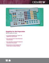
Simplicity That Makes Sense <br />
Everything in SIMPLE LOGIC is designed to work together,<br />
to be intuitive and easy to use. SIMPLE LOGIC spells it out for you:<br />
Lok-Ball for positive visual verification of correct seating<br />
OSSEOTITE ® implant surface for superior results even in poor quality bone<br />
Gold-colored trans-gingival collar for improved aesthetic appearance<br />
Innovative preparation coping for easy intra-oral adjustments<br />
Color-coding for matching components at a glance
Introduction<br />
This <strong>Surgical</strong> and <strong>Restorative</strong> <strong>Manual</strong> is designed with clear illustrations for easy step by step instruction<br />
on the placement and restoration of the <strong>TG</strong> OSSEOTITE ® implant.<br />
The surgical section dictates the placement protocols for each diameter of <strong>TG</strong> OSSEOTITE implant,<br />
instrument by instrument. The restorative section describes the protocol for fabrication of:<br />
• Single Unit<br />
• Multi-Unit<br />
• Overdentures<br />
Restoration types are divided by:<br />
• Cement Retained<br />
• Screw Retained<br />
<strong>Restorative</strong> steps identify each team member:<br />
• Surgeon<br />
• <strong>Restorative</strong> Dentist<br />
• Laboratory Technician<br />
Each procedure is further segmented by the use of direct or indirect restorative techniques<br />
with SIMPLE LOGIC, the <strong>TG</strong> Hex Abutment, and the <strong>TG</strong> O-Ring Abutment.<br />
3
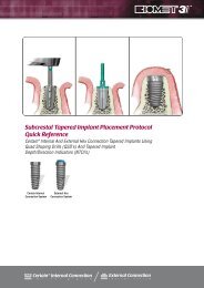
<strong>Surgical</strong> Placement<br />
<strong>TG</strong> OSSEOTITE Miniplant<br />
<strong>TG</strong> OSSEOTITE ® MINIPLANT ® (3.25)<br />
1-Instrumentation:<br />
Round Drill (RD100)<br />
Once the implant site has been<br />
determined, mark the site with<br />
a stainless steel Round Drill and<br />
penetrate the cortical bone.<br />
Set drill speed at approximately<br />
1,500 rpm for steps 1 through 5.<br />
4-Instrumentation: 2/3mm<br />
Pilot/Shaping Drill (PSD100)<br />
Use the 2/3mm Pilot/Shaping<br />
Drill to shape the coronal aspect<br />
of the implant site. Drill to the<br />
first laser etched depth marking<br />
for placement of a 3.25mm<br />
<strong>TG</strong> OSSEOTITE. <strong>TG</strong> O<br />
2-Instrumentation:<br />
2.3mm Twist Drill (ITD215)<br />
Proceed with the 2.3mm Twist<br />
Drill. Penetrate the bone at the<br />
marked site to the desired depth.<br />
5-Instrumentation:<br />
3.00mm Twist Drill (ITD315)<br />
Once proper alignment is<br />
verified using the Direction<br />
Indicator, proceed with<br />
the 3.00mm Twist Drill<br />
to the desired depth.<br />
3-Instrumentation: Direction<br />
Indicator (DI2310)*<br />
Verify the direction and position<br />
of the preparation by inserting<br />
the thin portion of the Direction<br />
Indicator into the osteotomy.<br />
* To help prevent accidental<br />
swallowing, a suture should<br />
be passed through the<br />
indicator hole, tied in a knot<br />
and cut, leaving a 2 inch<br />
thread.<br />
6-Instrumentation: Handpiece<br />
Connector (MDR10)<br />
Using the Handpiece Connector,<br />
pick up the implant and mount<br />
from the surgical tray. Carry<br />
the implant to the mouth facing<br />
upward to prevent accidental<br />
dislodging.<br />
4
<strong>TG</strong> OSSEOTITE ® MINIPLANT ® (3.25)<br />
7<br />
Place the implant in the prepared<br />
site at 15 to 20 rpm. The ICE<br />
design will allow smooth and<br />
precise implant placement<br />
without tapping in all but<br />
the most dense bone.The top<br />
thread of the implant should<br />
be positioned level with the<br />
crest of the bone.<br />
9-Instrumentation: Large Hex Driver<br />
(PHD02N or PHDO3N)*<br />
Insert the Large Hex Driver into<br />
the cover screw and pick it up<br />
from the tray. Thread the cover<br />
screw into the implant until tight.<br />
8-Instrumentation: Large Hex<br />
Driver (PHD02N)* and Open<br />
End Wrench (CW100)<br />
Holding the mount with<br />
the Open End Wrench, turn<br />
the mount screw a half turn in<br />
the counter-clockwise direction<br />
(left) to loosen using the Large<br />
Hex Driver. It is not necessary<br />
to remove the mount screw. Then<br />
unscrew the mount using the<br />
Open End Wrench by turning<br />
the mount in a counter-clockwise<br />
direction one full rotation and<br />
remove the mount.<br />
* To help prevent accidental swallowing, a suture should be<br />
passed through the spinner hole of the Large Hex Driver,<br />
tied in a knot and cut, leaving a 2 inch thread.<br />
10<br />
Close tissue and suture leaving<br />
the cover screw exposed.<br />
5
<strong>Surgical</strong> Placement<br />
<strong>TG</strong> OSSEOTITE Standard<br />
<strong>TG</strong> OSSEOTITE ® STANDARD (4.0)<br />
1-Instrumentation:<br />
Round Drill (RD100)<br />
Once the implant site has been<br />
determined, mark the site with<br />
a stainless steel Round Drill and<br />
penetrate the cortical bone.<br />
Set drill speed at approximately<br />
1,500 rpm for steps 1 through 5.<br />
4-Instrumentation: 2/3mm<br />
Pilot/Shaping Drill (PSD100)<br />
Use the 2/3mm Pilot/Shaping<br />
Drill to shape the coronal aspect<br />
of the implant site. Drill to the<br />
first laser etched depth marking<br />
for placement of a 4.0mm<br />
<strong>TG</strong> OSSEOTITE. <strong>TG</strong> O<br />
2-Instrumentation:<br />
2.3mm Twist Drill (ITD215)<br />
Proceed with the 2.3mm Twist<br />
Drill. Penetrate the bone at the<br />
marked site to the desired depth.<br />
5-Instrumentation:<br />
3.25MM Twist Drill (ITD3215)<br />
Once proper alignment is<br />
verified using the Direction<br />
Indicator proceed with the<br />
3.25mm Twist Drill to the<br />
desired depth.<br />
3-Instrumentation: Direction<br />
Indicator (DI2310)*<br />
Verify the direction and position<br />
of the preparation by inserting<br />
the thin portion of the Direction<br />
Indicator into the osteotomy.<br />
* To help prevent accidental<br />
swallowing, a suture should<br />
be passed through the<br />
indicator hole, tied in a knot<br />
and cut, leaving a 2 inch<br />
thread.<br />
6-Instrumentation: Handpiece<br />
Connector (MDR10)<br />
Using the Handpiece Connector,<br />
pick up the implant and mount<br />
from the surgical tray. Carry<br />
the implant to the mouth facing<br />
upward to prevent accidental<br />
dislodging.<br />
6
<strong>TG</strong> OSSEOTITE ® STANDARD (4.0)<br />
7<br />
9-Instrumentation: Large Hex Driver<br />
(PHD02N or PHDO3N)*<br />
Place the implant in the prepared<br />
site at 15 to 20 rpm. The ICE<br />
design will allow smooth<br />
and precise implant placement<br />
without tapping in all but the<br />
most dense bone. The top<br />
thread of the implant should<br />
be positioned level with the<br />
crest of the bone.<br />
Insert the Large Hex Driver into<br />
the cover screw and pick it up<br />
from the tray. Thread the cover<br />
screw into the implant until tight.<br />
8-Instrumentation: Large Hex Driver<br />
(PHD02N)* and Open End Wrench<br />
(CW100)<br />
Holding the mount with<br />
the Open End Wrench, turn<br />
the mount screw a half turn in<br />
the counter-clockwise direction<br />
(left) to loosen using the Large<br />
Hex Driver. It is not necessary<br />
to remove the mount screw.<br />
Then unscrew the mount using<br />
the Open End Wrench by turning<br />
the mount in a counter-clockwise<br />
direction one full rotation and<br />
remove the mount.<br />
* To help prevent accidental swallowing, a suture should be passed<br />
through the spinner hole of the Large Hex Driver, tied in a knot<br />
and cut, leaving a 2 inch thread.<br />
10<br />
Close tissue and suture leaving<br />
the cover screw exposed.<br />
7
<strong>Surgical</strong> Placement<br />
<strong>TG</strong> OSSEOTITE Wide<br />
<strong>TG</strong> OSSEOTITE ® WIDE (5.0)<br />
1-Instrumentation:<br />
Round Drill (RD100)<br />
Once the implant site has been<br />
determined, mark the site with<br />
a stainless steel Round Drill and<br />
penetrate the cortical bone.<br />
Set drill speed at approximately<br />
1,500 rpm for steps 1 through 5.<br />
4-Instrumentation: 2/3mm<br />
Pilot/Shaping Drill (PSD100)<br />
Use the 2/3mm Pilot Shaping<br />
Drill to shape the coronal aspect<br />
of the implant site. Drill to the<br />
second laser etched depth<br />
marking for placement of a<br />
5.0mm <strong>TG</strong> OSSEOTITE.<br />
* Use of the PSD100 is optional<br />
for placement of a 5.0mm<br />
<strong>TG</strong> OSSEOTITE implant.<br />
2-Instrumentation:<br />
2.3mm Twist Drill (ITD215)<br />
Proceed with the 2.3mm Twist<br />
Drill. Penetrate the bone at the<br />
marked site to the desired depth.<br />
5-Instrumentation:<br />
3.00mm Twist Drill (ITD315)<br />
Once proper alignment is<br />
verified using the Direction<br />
Indicator, proceed with<br />
the 3.00mm Twist Drill<br />
to the desired depth.<br />
8<br />
3-Instrumentation:<br />
Indicator (DI2310)*<br />
Verify the direction and position<br />
of the preparation by inserting<br />
the thin portion of the Direction<br />
Indicator into the osteotomy.<br />
* To help prevent accidental<br />
swallowing, a suture should<br />
be passed through the<br />
indicator hole, tied in a knot<br />
and cut, leaving a 2 inch<br />
thread.<br />
6-Instrumentation: 5.0mm<br />
Pilot/Countersink Drill (CD500)<br />
Use the first cutting groove on<br />
the 5.0mm Pilot Countersink<br />
Drill (CD500) to widen the<br />
coronal aspect of the osteotomy<br />
to provide a guide for the<br />
4.25mm Twist Drill to enter the<br />
osteotomy. Decrease drill speed<br />
to approximately 800 rpm for<br />
steps 6 and 7.<br />
Do not drill to the laser etched<br />
line. Stop at the step below it.
<strong>TG</strong> OSSEOTITE ® WIDE (5.0)<br />
7-Instrumentation:<br />
4.25mm Twist Drill (ITD423)<br />
Once the coronal aspect of the<br />
osteotomy has been piloted,<br />
proceed with the 4.25mm Twist<br />
Drill to the desired depth.<br />
10-Instrumentation: Large Hex Driver<br />
(PHD02N)* and Open-End Wrench<br />
(CW100)<br />
Holding the mount with the<br />
Open-End Wrench, turn the mount<br />
screw a half turn in the counterclockwise<br />
direction (left) to loosen<br />
using the Large Hex Driver. It is not<br />
necessary to remove the mount<br />
screw. Then unscrew the mount<br />
using the Open End Wrench by<br />
turning the mount in a counterclockwise<br />
direction one full rotation<br />
and remove the mount. * To help<br />
prevent accidental swallowing, a suture should be passed through the spinner<br />
hole of the Large Hex Driver, tied in a knot and cut, leaving a 2 inch thread.<br />
8-Instrumentation:<br />
Handpiece Connector (MDR10)<br />
Using the Handpiece Connector,<br />
pick up the implant and mount<br />
from the surgical tray. Carry<br />
the implant to the mouth facing<br />
upward to prevent accidental<br />
dislodging.<br />
11-Instrumentation: Large Hex<br />
Driver (PHD02N or PHDO3N)*<br />
Insert the Large Hex Driver into<br />
the cover screw and pick it up<br />
from the tray. Thread the cover<br />
screw into the implant until tight.<br />
9<br />
Place the implant in the prepared<br />
site at 15 to 20 rpm. The ICE<br />
design will allow smooth and<br />
precise implant placement<br />
without tapping, in all but the<br />
most dense bone. The top<br />
thread of the implant should<br />
be positioned level with the<br />
crest of the bone.<br />
12<br />
Close tissue and suture leaving<br />
the cover screw exposed.<br />
9
Clinical Tips for Placing <strong>TG</strong> OSSEOTITE ® Implants<br />
The Pilot Shaping Drill (PSD100) is necessary for shaping the coronal aspect of the 3.25mm or 4.0mm<br />
<strong>TG</strong> OSSEOTITE implant site. The drill is used after the 2.3mm drill and prior to the 3.00mm or 3.25mm drill.<br />
The (PSD100) is optional for placement of a 5.0mm <strong>TG</strong> OSSEOTITE.<br />
If a clinician chooses to place the <strong>TG</strong> OSSEOTITE implant below the recommended level (the top or<br />
terminus of the thread level with the crest of the bone), the depth of the osteotomy and coronal aspect<br />
of the osteotomy needs to be modified.<br />
A final drill diameter of 3.25mm is recommended to place the 4.0mm <strong>TG</strong> OSSEOTITE implant. Excessive<br />
torque will be generated if the osteotomy is prepared to a smaller diameter, especially in dense bone.<br />
As with all 3i implants, the Handpiece Connector (MDR10) should be used to place the <strong>TG</strong> OSSEOTITE<br />
implant. The Ratchet Wrench (WR150) should only be used for final tightening.<br />
The Positive Reversing Mount (<strong>TG</strong>PRM), should only be used to back-out a <strong>TG</strong> OSSEOTITE implant.<br />
Using the reversing mount in a forward direction may lock the reversing mount onto the implant.<br />
10
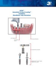
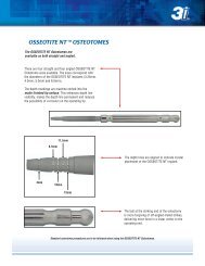
<strong>TG</strong> OSSEOTITE ® Positive Reversing Mount<br />
Figure 1 Step 1 Step 2 Step 3<br />
The Positive Reversing Mount is comprised of two<br />
separate components, the mount body and the mount<br />
screw (Figure 1).<br />
Mount Screw<br />
1<br />
2<br />
3<br />
Retract the mount screw up into the mount body.<br />
Screw the mount body clockwise into the implant until<br />
seated, using your fingers.<br />
NOTE: Tightening is unnecessary.<br />
Thread the mount screw into the implant with fingers until<br />
seated, then tighten using the Open End Wrench (CW100)<br />
Mount Body<br />
Step 4<br />
Step 5<br />
4<br />
Place the Ratchet Wrench (WR150) onto mount for<br />
counter-clockwise rotation to reposition the implant<br />
to the desired level.<br />
5<br />
Flip over the Ratchet Wrench for right hand rotation<br />
to prevent the implant from rotating while loosening<br />
the mount screw. Using the Open End Wrench (CW100)<br />
loosen the mount screw two full counter-clockwise<br />
rotations. Then using the Ratchet Wrench (WR150)<br />
in a counter-clockwise rotation remove the mount.<br />
11
- Indirect Technique<br />
Cemented Restorations - Single Unit<br />
1-SURGEON OR<br />
RESTORATIVE DENTIST<br />
4<br />
Remove the cover screw from the implant using the Large Hex Driver<br />
or driver tip. To prevent accidental swallowing, thread floss through<br />
the spinner on the driver as a precaution.<br />
Torque the <strong>TG</strong> Post into place at 32-35Ncm using the <strong>TG</strong> Post Driver Tip.<br />
2<br />
5<br />
Insert the <strong>TG</strong> Try-In Post into the implant. Press firmly until it<br />
frictionally holds in place. Determine the proper height and angulation<br />
for the final post. Allow for 2mm between the Try-In Post and<br />
opposing occlusion for the height of the Lok-Ball, Lok-Cap<br />
and the porcelain/metal thickness of the final restoration. To prevent<br />
accidental swallowing, thread floss through the post as a precaution.<br />
The <strong>TG</strong> Post is now in<br />
place and ready for<br />
impressioning. (If the<br />
surgeon has placed<br />
the post, a Lok-Cap will<br />
now be placed and<br />
the patient is sent to the restorative dentist. See step 10). A stock or<br />
custom closed top impression tray is used for the indirect technique.<br />
A medium body impression material is recommended.<br />
3<br />
6-RESTORATIVE<br />
DENTIST<br />
Select the proper <strong>TG</strong> Post by matching the colors. Place the <strong>TG</strong> Post<br />
using the <strong>TG</strong> Post Driver.<br />
Select the proper impression coping by matching the colors. Place the<br />
impression coping onto the post by lining up the flat side. Push down<br />
until it engages the Lok-Ball on top of the post. The impression<br />
coping is fully seated when the Lok-Ball is clearly visible above<br />
the top of the coping.<br />
12
7<br />
10<br />
Syringe impression material around the entire impression coping.<br />
Place the Lok-Cap TM onto the <strong>TG</strong> Post and press firmly until it engages<br />
the Lok-Ball TM on the top of the post. The Lok-Cap is fully seated when<br />
the Lok-Ball is clearly visible above the top of the cap.<br />
8<br />
11-LABORATORY<br />
Fill the impression tray with material and insert into the mouth. Allow<br />
the impression material to set per the manufacturer’s instructions.<br />
Select the proper <strong>TG</strong> Post Analog by matching the colors. Insert the<br />
analog into the impression coping, lining up the flat side, and press<br />
firmly until the Lok-Ball engages.<br />
9<br />
12<br />
Remove the impression from the mouth and verify that the material<br />
has completely adapted around the impression coping.<br />
Note: If implants are divergent, the impression copings may not pick<br />
up in the impression. If this happens, remove the impression coping<br />
from the post, place the analog into it and reinsert it into the impression<br />
by lining up the flat side.<br />
Pour the model in stone. If the implant collar is subgingival, syringe<br />
a soft tissue material around the analog collar before pouring in stone.<br />
Articulate with opposing model.<br />
13
Continued<br />
Cemented Restorations - Single Unit<br />
13<br />
16<br />
Remove the Lok-Ball from the top of the analog using a carbide bur.<br />
Place the single unit castable coping on the analog, lining up the flat<br />
side, and tack it down to the analog collar with a few drops of wax.<br />
Grind the castable coping to match the preparation of the post analog.<br />
Note: The castable copings are made to provide cement space around<br />
the post.<br />
14<br />
17<br />
Place the <strong>TG</strong> Post Preparation Coping over the analog, lining up the flat<br />
side, and push down to the analog collar until it frictionally holds<br />
in place.<br />
Wax the single unit PFM coping to the castable coping. Remove the<br />
wax coping from the analog and remove any wax around the collar<br />
margin area before investing.<br />
15<br />
18<br />
Using a carbide bur, prepare the analog and Preparation Coping<br />
together as necessary for height and angulation. Remove the<br />
Preparation Coping and prepare to send it to the restorative dentist<br />
with the finished restoration.<br />
Invest, burnout and cast the single unit PFM coping in a semi-precious<br />
or high noble alloy. Devest and finish the coping.<br />
14
19<br />
22<br />
Opaque and build the porcelain on the single unit coping.<br />
Stain and glaze for delivery.<br />
Try the single unit PFM crown on the <strong>TG</strong> Post and verify a passive fit<br />
to the margin on the implant collar. Take a radiograph if crown margin<br />
is subgingival.<br />
20-RESTORATIVE<br />
DENTIST<br />
23<br />
Remove the Lok-Cap from the <strong>TG</strong> Post. Remove the Lok-Ball<br />
from the post using orthodontic pliers and discard it.<br />
Cement the single unit crown onto the <strong>TG</strong> Post using a permanent<br />
or temporary cement. Verify a passive fit to the margin on the implant<br />
collar. Make any occlusal adjustments necessary. Final restoration<br />
is complete.<br />
21<br />
Place the Preparation Coping onto the <strong>TG</strong> Post, lining up the flat<br />
side, then press firmly to the implant collar until it frictionally holds<br />
in place. Using a carbide bur, with copious irrigation, prepare the<br />
post so it is even with the level of the Preparation Coping. Remove<br />
the Preparation Coping.<br />
15
<strong>TG</strong> Post - Direct Technique<br />
Cemented Restorations - Single Unit<br />
1-SURGEON OR<br />
RESTORATIVE DENTIST<br />
4<br />
Remove the cover screw from the implant using the Large Hex Driver<br />
or driver tip. To prevent accidental swallowing, thread floss through<br />
the spinner on the driver as a precaution.<br />
Torque the <strong>TG</strong> Post into place at 32-35Ncm using the <strong>TG</strong> Post Driver<br />
Tip. (If the surgeon has placed the post, a Lok-Cap TM is placed and the<br />
patient is sent to the restorative dentist).<br />
2<br />
5-RESTORATIVE<br />
DENTIST<br />
Insert the <strong>TG</strong> Try-In Post into the implant. Press firmly until it frictionally<br />
holds in place. Determine the proper height and angulation for the final<br />
post. Allow for 2mm of space between the Try-In Post and opposing<br />
occlusion for the height of the porcelain/metal thickness of the final<br />
restoration. To prevent accidental swallowing, thread floss through<br />
the post as a precaution.<br />
Remove the Lok-Ball TM from the <strong>TG</strong> Post using orthodontic pliers<br />
and discard it.<br />
3<br />
6<br />
Select the proper <strong>TG</strong> Post by matching the colors. Place the <strong>TG</strong> Post<br />
using the <strong>TG</strong> Post Driver.<br />
Prepare the <strong>TG</strong> Post using a carbide bur, with copious irrigation,<br />
as necessary for height and angulation. The post is now ready<br />
for impressioning. A stock or custom closed top impression tray<br />
is used for the direct technique. A medium body impression material<br />
is recommended.<br />
16
7<br />
10 LABORATORY<br />
Syringe impression material down through the gingival sulcus onto<br />
the implant collar to pick up the margin area. Also syringe around<br />
the entire prepared post.<br />
Pin and pour the model in stone using a strengthening wire in the post<br />
area. If the implant collar is subgingival, syringe a soft tissue material<br />
around the base of the impression of the post before pouring in stone.<br />
Articulate with opposing model.<br />
8<br />
11<br />
Fill the impression tray with material and insert into the mouth. Allow<br />
the impression material to set per the manufacturer’s instructions.<br />
Apply a thin layer of die spacer to the stone post only. Wax the single<br />
unit PFM coping to the stone die.<br />
9<br />
12<br />
Remove the impression from the mouth and verify marginal accuracy.<br />
Fabricate a temporary crown which adapts to the margin at the top<br />
of the implant collar and temporarily cement it into place.<br />
Invest, burn-out and cast the single unit PFM coping in a semi-precious<br />
or high noble alloy. Devest and finish the coping.<br />
17
<strong>TG</strong> Post Continued<br />
Cemented Restorations - Single Unit<br />
13<br />
Opaque and build the porcelain on the single unit coping. Stain and<br />
glaze for delivery.<br />
14-RESTORATIVE<br />
DENTIST<br />
Remove the temporary crown and clean away cement. Try the single<br />
unit PFM crown on the <strong>TG</strong> Post and verify a passive fit to the margin<br />
on the implant collar. Take a radiograph if crown margin is subgingival.<br />
15<br />
Cement the single unit crown onto the <strong>TG</strong> Post using a permanent<br />
or temporary cement. Verify a passive fit to the margin on the implant<br />
collar. Make any occlusal adjustments necessary. Final restoration<br />
is complete.<br />
18
<strong>TG</strong> PreAngled Post - Direct Technique<br />
Cemented Restorations - Single Unit<br />
1-RESTORATIVE<br />
DENTIST<br />
4<br />
Remove the cover screw from the implant using the Large Hex Driver<br />
or driver tip. To prevent accidental swallowing, thread floss through<br />
the spinner on the driver as a precaution.<br />
Place the hex screw on the Large Hex Driver and screw into place until<br />
tight. Torque the hex screw into place at 32-35Ncm using the Large<br />
Hex Driver tip.<br />
2<br />
5<br />
Insert the <strong>TG</strong> Try-In Post into the implant. Press firmly until it<br />
frictionally holds in place. Determine the proper height and angulation<br />
for the final post. To prevent accidental swallowing, thread floss<br />
through the post as a precaution.<br />
Prepare the <strong>TG</strong> PreAngled Post using a carbide bur with copious<br />
irrigation.<br />
DO NOT PREPARE THE AREA OPPOSITE THE ACCESS HOLE.<br />
3<br />
6<br />
Select the proper <strong>TG</strong> PreAngled Post by matching the colors. Place<br />
the post in the position to correct the angulation using your fingers.<br />
Press firmly into the implant morse taper.<br />
Place a protective material over the screw head. Fill the access hole<br />
with composite or another material of choice.<br />
19
<strong>TG</strong> PreAngled Post Continued<br />
Cemented Restorations - Single Unit<br />
7<br />
10-LABORATORY<br />
Syringe impression material down through the gingival sulcus onto<br />
the implant collar to pick up the margin area. Also syringe around<br />
the entire prepared post.<br />
Pin and pour the model in stone using a strengthening wire in the post<br />
area. If the implant collar is subgingival, syringe a soft tissue material<br />
around the base of the impression of the post before pouring in stone.<br />
Articulate with opposing model.<br />
8<br />
11<br />
Fill the impression tray with material and insert into the mouth. Allow<br />
the impression material to set per the manufacturer’s instructions.<br />
Apply a thin layer of die spacer to the stone post only. Wax the single<br />
unit PFM coping to the stone die.<br />
9<br />
12<br />
Remove the impression from the mouth and verify marginal accuracy.<br />
Fabricate a temporary crown which adapts to the margin at the top<br />
of the implant collar and temporarily cement it into place.<br />
Invest, burnout and cast the single unit PFM coping in a semi-precious<br />
or high noble alloy. Devest and finish the coping.<br />
20
13<br />
Opaque and build the porcelain on the single unit coping. Stain and<br />
glaze for delivery.<br />
14-RESTORATIVE<br />
DENTIST<br />
Remove the temporary crown and clean away cement. Try the single<br />
unit PFM crown on the <strong>TG</strong> PreAngled Post and verify a passive fit<br />
to the margin on the implant collar. Take a radiograph if crown margin<br />
is subgingival.<br />
15<br />
Cement the single unit crown onto the <strong>TG</strong> PreAngled Post using<br />
a permanent or temporary cement. Verify a passive fit to the margin<br />
on the implant collar. Make any occlusal adjustments necessary.<br />
Final restoration is complete.<br />
21
<strong>TG</strong> Hex Abutment<br />
Screw Retained Restorations - Single Unit<br />
1-SURGEON OR<br />
RESTORATIVE<br />
DENTIST<br />
4<br />
Remove the cover screw from the implant using the Large Hex Driver<br />
or driver tip. To prevent accidental swallowing, thread floss through<br />
the spinner on the driver as a precaution.<br />
Torque the <strong>TG</strong> Hex Abutment into the implant at 32-35Ncm using<br />
the <strong>TG</strong> Hex Abutment Driver Tip.<br />
2<br />
5<br />
Place the <strong>TG</strong> Hex Abutment onto the <strong>TG</strong> Hex Abutment Driver.<br />
The abutment can be retained on the driver by engaging the hex<br />
and turning the spinner on the end clockwise. To prevent accidental<br />
swallowing, thread floss through the spinner on the driver<br />
as a precaution.<br />
The <strong>TG</strong> Hex Abutment is now in place and ready for impressioning.<br />
(If the surgeon places the abutment, a <strong>TG</strong> Hex Abutment Healing Cap<br />
is placed and the patient is sent to the restorative dentist. See step<br />
12A). A transfer or pick-up impression technique may be used to<br />
impress the <strong>TG</strong> Hex Abutment. For transfer, continue on to step 6A.<br />
For pick-up, continue to 6B on page 24.<br />
3<br />
6A-RESTORATIVE<br />
DENTIST<br />
Thread the <strong>TG</strong> Hex Abutment into the implant and hand tighten.<br />
The driver is released from the abutment by turning the spinner<br />
counter-clockwise.<br />
Transfer Technique<br />
Place the Twist-Lock Transfer Coping over the hex on the abutment.<br />
Thread the transfer coping screw into the abutment using the Transfer<br />
Impression Coping Driver.<br />
22
7A<br />
10A<br />
Take a radiograph to verify that the impression coping is seated<br />
passively on the hex and collar of the implant.<br />
Fill the impression tray with material and insert into the mouth. Allow<br />
impression material to set per the manufacturer's instructions.<br />
8A<br />
11A<br />
A custom or stock closed top impression tray is used for the<br />
Twist-Lock TM transfer impression technique. A medium body<br />
impression material is recommended.<br />
Remove the impression from the mouth and verify that the material<br />
completely adapted around the coping.<br />
9A<br />
12A<br />
Syringe impression material around the entire Twist-Lock<br />
Impression Coping.<br />
Thread the <strong>TG</strong> Hex Abutment Healing Cap into the abutment using<br />
the Large Hex Driver or driver tip.<br />
23
<strong>TG</strong> Hex Abutment Continued<br />
Screw Retained Restorations - Single Unit<br />
13A-LABORATORY<br />
6B-RESTORATIVE<br />
DENTIST<br />
Screw the Twist-Lock Transfer Coping onto the <strong>TG</strong> Hex Abutment<br />
Analog. Visually verify that it is passively seated.<br />
Pick-Up Technique<br />
Place the Pick-Up Impression Coping over the hex on the abutment.<br />
Thread the Pick-Up Coping Screw into the abutment using your fingers<br />
then hand tighten using the Large Hex Driver.<br />
14A<br />
7B<br />
Holding onto the analog, press the Twist-Lock Coping into the<br />
impression firmly, then gently twist until the three orientation notches<br />
lock into place.<br />
Take a radiograph to verify that the impression coping is seated<br />
passively on the hex and collar of the implant.<br />
15A<br />
8B<br />
Pour the model in stone. If the implant collar is subgingival, syringe<br />
a soft tissue material around the analog collar before pouring in stone.<br />
Articulate with opposing model.<br />
Go to step 16<br />
A custom or stock open top impression tray is used for the pick-up<br />
impression technique. Cut a small hole in the tray for the screw<br />
to protrude through. A medium body impression material is<br />
recommended.<br />
24
9B<br />
12B<br />
Syringe impression material around the entire Pick-Up<br />
Impression Coping.<br />
Unscrew the Pick-Up Impression Coping Screw, using the Large Hex<br />
Driver and remove it. Remove the impression from the mouth and<br />
verify that the material completely adapted around the coping.<br />
10B<br />
13B<br />
Fill the impression tray with material and insert into the mouth.<br />
Be sure the screw protrudes from the tray.<br />
Thread the <strong>TG</strong> Hex Abutment Healing Cap into the abutment using<br />
the Large Hex Driver or driver tip<br />
11B<br />
14B-LABORATORY<br />
Wipe impression material off of the top of the screw before it sets.<br />
Allow impression material to set per the manufacturer’s instructions.<br />
Place the <strong>TG</strong> Hex Abutment Analog into the coping engaging the hex.<br />
Push the impression coping screw back into the coping and tighten<br />
it using the Large Hex Driver. Verify the coping is passively seated<br />
on the analog.<br />
25
<strong>TG</strong> Hex Abutment Continued<br />
Screw Retained Restorations - Single Unit<br />
15B<br />
18<br />
Pour the model in stone. If the implant collar is subgingival syringe a<br />
soft tissue material around the analog collar before pouring in stone.<br />
Articulate with opposing model.<br />
Opaque and build the porcelain on the single unit coping then stain<br />
and glaze for delivery.<br />
16<br />
19-RESTORATIVE<br />
DENTIST<br />
Screw the hexed gold cylinder into the analog using the waxing screw<br />
or retaining screw. Cut the wax sleeve to the proper height and wax<br />
the single unit PFM coping to it.<br />
Remove the healing cap. Place the single unit onto the <strong>TG</strong> Hex<br />
Abutment. Screw the hex Gold-Tite retaining screw into the<br />
abutment and torque to 10Ncm using the Large Hex Driver Tip. Take<br />
a radiograph to verify a passive fit to the margin on the implant collar.<br />
Make any occlusal adjustments. Place a protective material over the<br />
screw head. Seal the access hole with composite or another material<br />
of choice. Final restoration is complete.<br />
17<br />
Invest, burnout and cast the single unit PFM coping to the gold<br />
cylinder using a semi-precious or high noble alloy. Devest and finish<br />
the coping.<br />
26
Cement Retained - Multi-Unit<br />
- Indirect Technique<br />
1-SURGEON OR<br />
RESTORATIVE<br />
DENTIST<br />
4<br />
Remove the cover screws from the implants using the Large Hex<br />
Driver or driver tip. To prevent accidental swallowing, thread floss<br />
through the spinner on the driver as a precaution.<br />
Torque the <strong>TG</strong> Posts into place at 32-35Ncm using the <strong>TG</strong> Post Driver Tip.<br />
2<br />
5<br />
Insert the <strong>TG</strong> Try-In Posts into the implants. Press firmly until they<br />
frictionally hold in place. Determine the proper height and angulation<br />
for the final posts. Allow for 2mm of space between the Try-In Post<br />
and opposing occlusion for the height of the Lok-Ball and Lok-Cap<br />
and the porcelain/metal thickness of the final restoration. To prevent<br />
accidental swallowing, thread floss through the posts as a precaution.<br />
The <strong>TG</strong> Posts are now in place and ready for impressioning.<br />
(If the surgeon has placed the posts, the Lok-Caps will be placed<br />
and the patient is sent to the restorative dentist. See step 10).<br />
A stock or custom closed top impression tray is used for the indirect<br />
technique. A medium body impression material is recommended.<br />
3<br />
6-RESTORATIVE<br />
DENTIST<br />
Select the proper <strong>TG</strong> Posts by matching the colors. Place the <strong>TG</strong> Posts<br />
using the <strong>TG</strong> Post Driver.<br />
Select the proper impression copings by matching the colors. Place<br />
the impression copings onto the posts by lining up the flat side.<br />
Push down until they engage the Lok-Ball on top of the post.<br />
The impression copings are fully seated when the Lok-Ball is clearly<br />
visible above the top of the copings.<br />
27
Continued<br />
Cement Retained - Multi-Unit<br />
7<br />
10<br />
Syringe impression material around each entire impression coping.<br />
Place the Lok-Caps onto the <strong>TG</strong> Posts and press firmly until they<br />
engage the Lok-Ball on the top of the posts. The Lok-Cap is fully<br />
seated when the Lok-Ball is clearly visible above the top of the cap.<br />
8<br />
11-LABORATORY<br />
Fill the impression tray with material and insert into the mouth. Allow<br />
the impression material to set per the manufacturer’s instructions.<br />
Select the proper <strong>TG</strong> Post Analogs by matching the colors. Insert the<br />
analogs into the impression copings, lining up the flat side, and press<br />
firmly until the Lok-Ball engages.<br />
9<br />
12<br />
Remove the impression from the mouth and verify that the material<br />
has completely adapted around the impression copings.<br />
Note: If implants are divergent the impression copings may not pick<br />
up in the impression. If this happens, remove the impression copings<br />
from the posts, place the analogs into them and reinsert them into the<br />
impression by lining up the flat side.<br />
28<br />
Pour the model in stone. If the implant collars are subgingival syringe<br />
a soft tissue material around the analog collars before pouring in<br />
stone. Articulate with opposing model.
13<br />
16<br />
Remove the Lok-Balls from the top of the analogs using a carbide bur.<br />
Place the multi-unit castable copings on the analogs, and tack them<br />
down to the analog collars with a few drops of wax. Grind the castable<br />
copings to match the preparation of the post analogs.<br />
Note: The castable copings are made to provide cement space around<br />
the post.<br />
14<br />
17<br />
Place the <strong>TG</strong> Post Preparation Copings over the analogs, lining<br />
up the flat side, and push down to the analog collar until they<br />
frictionally hold in place.<br />
Wax the multi-unit PFM framework to the castable copings.<br />
Remove the wax up from the analogs and remove any wax around<br />
the collar margin areas before investing.<br />
15<br />
18<br />
Using a carbide bur, prepare the analogs and Preparation Copings<br />
together as necessary for height and angulation. Remove and number<br />
the Preparation Copings. Prepare to send them to the restorative<br />
dentist with the finished restoration.<br />
Invest, burnout and cast the multi-unit PFM framework in a<br />
semi-precious or high noble alloy. Devest and finish the framework.<br />
29
Continued<br />
Cement Retained - Multi-Unit<br />
19<br />
22<br />
Opaque and build the porcelain on the multi-unit framework.<br />
Stain and glaze for delivery.<br />
Try the multi-unit PFM bridge on the <strong>TG</strong> Posts and verify a passive fit<br />
to the margins on the implant collars. Take a radiograph if crown<br />
margins are subgingival.<br />
20-RESTORATIVE<br />
DENTIST<br />
23<br />
Remove the Lok-Caps from the <strong>TG</strong> Posts. Remove the Lok-Balls<br />
from the posts using orthodontic pliers and discard them.<br />
Cement the multi-unit bridge onto the <strong>TG</strong> Posts using a permanent or<br />
temporary cement. Verify a passive fit to the margins on the implant<br />
collars. Make any occlusal adjustments necessary. Final restoration<br />
is complete.<br />
21<br />
Place the Preparation Copings onto the <strong>TG</strong> Posts, lining up the flat<br />
side. Press firmly to the implant collar until they frictionally hold in<br />
place. Using a carbide bur, with copious irrigation, prepare the posts<br />
so they are even with the level of the Preparation Copings. Remove<br />
the Preparation Copings.<br />
30
<strong>TG</strong> Post and <strong>TG</strong> PreAngled Post - Direct Technique<br />
Cement Retained - Multi-Unit<br />
1-RESTORATIVE<br />
DENTIST<br />
4<br />
Remove the cover screws from the implants using the Large Hex<br />
Driver or driver tip. To prevent accidental swallowing, thread floss<br />
through the spinner on the driver as a precaution.<br />
Prepare the <strong>TG</strong> PreAngled Post using a carbide bur with copious<br />
irrigation. DO NOT PREPARE THE AREA OPPOSITE THE ACCESS<br />
HOLE. Remove the Lok-Ball from the <strong>TG</strong> Post using orthodontic<br />
pliers and discard it. Prepare the <strong>TG</strong> Post as necessary for height<br />
and angulation using a carbide bur with copious irrigation.<br />
2<br />
5<br />
Insert the <strong>TG</strong> Try-In Posts into the implants. Press firmly until they<br />
frictionally hold in place. Determine the proper height and angulation<br />
for the final posts. To prevent accidental swallowing, thread floss<br />
through the posts as a precaution.<br />
On the <strong>TG</strong> PreAngled Post, place a protective material over the screw<br />
head and fill the access hole with composite or another material<br />
of choice.<br />
3<br />
6<br />
Select the proper <strong>TG</strong> Post and <strong>TG</strong> PreAngled Post by matching<br />
the colors. Place the <strong>TG</strong> PreAngled Post in the position to correct<br />
the angulation using your fingers. Press firmly into the implant morse<br />
taper. Place the hex screw on the Large Hex Driver and screw into<br />
place until tight. Torque the hex screw into place at 32-35Ncm using<br />
the Large Hex Driver Tip. Place the <strong>TG</strong> Post using the <strong>TG</strong> Post Driver.<br />
Torque the <strong>TG</strong> Post into place at 32-35Ncm using the <strong>TG</strong> Post Driver Tip.<br />
Syringe impression material down through the gingival sulcus onto the<br />
implant collars to pick up the margin areas. Also syringe around each<br />
of the entire prepared posts.<br />
31
<strong>TG</strong> Post and <strong>TG</strong> PreAngled Post Continued<br />
Cement Retained - Multi-Unit<br />
7<br />
10<br />
Fill the impression tray with material and insert into the mouth. Allow<br />
the impression material to set per the manufacturer’s instructions.<br />
Apply a thin layer of die spacer to the stone posts only.<br />
Wax the multi-unit PFM bridge framework to the stone dies.<br />
8<br />
11<br />
Remove the impression from the mouth and verify marginal accuracy.<br />
Fabricate a temporary bridge which adapts to the margins at the top<br />
of the implant collars and temporarily cement it into place.<br />
Invest, burnout and cast the multi-unit PFM framework in a<br />
semi-precious or high noble alloy. Devest and finish the framework.<br />
9 -LABORATORY<br />
12<br />
Pin and pour the model in stone using a strengthening wire in the<br />
post areas. If the implant collars are subgingival syringe a soft tissue<br />
material around the base of the impression of the posts before<br />
pouring in stone. Articulate with opposing model.<br />
Opaque and build the porcelain on the multi-unit framework. Stain<br />
and glaze for delivery.<br />
32
13-RESTORATIVE<br />
DENTIST<br />
Remove the temporary bridge and clean away cement. Try the<br />
multi-unit PFM bridge onto the posts and verify a passive fit to the<br />
margins on the implant collars. Take a radiograph if crown margins<br />
are subgingival.<br />
14<br />
Cement the multi-unit bridge onto the <strong>TG</strong> Post and <strong>TG</strong> PreAngled Post<br />
using a permanent or temporary cement. Verify a passive fit to the<br />
margins on the implant collars. Make any occlusal adjustments<br />
necessary. Final restoration is complete.<br />
33
<strong>TG</strong> Hex Abutment<br />
Screw Retained Restoration - Multi-Unit<br />
1-SURGEON OR<br />
RESTORATIVE<br />
DENTIST<br />
4<br />
Remove the cover screws from the implants using the Large Hex<br />
Driver or driver tip. To prevent accidental swallowing, thread floss<br />
through the spinner on the driver as a precaution.<br />
Torque the <strong>TG</strong> Hex Abutments into the implants at 32-35Ncm using<br />
the <strong>TG</strong> Hex Abutment Driver Tip.<br />
2<br />
5<br />
Place the <strong>TG</strong> Hex Abutment onto the <strong>TG</strong> Hex Abutment Driver.<br />
The abutment can be retained on the driver by engaging the hex<br />
and turning the spinner on the end clockwise. To prevent accidental<br />
swallowing, thread floss through the spinner on the driver as a<br />
precaution.<br />
The <strong>TG</strong> Hex Abutments are now in place and ready for impressioning.<br />
(If the surgeon places the abutments <strong>TG</strong> Hex Abutment Healing Caps<br />
are placed and the patient is sent to the restorative dentist. See step<br />
12A). A transfer or pick-up impression technique may be used to<br />
impress the <strong>TG</strong> Hex Abutments. For transfer, continue to step 6A.<br />
For pick-up, continue to 6B on page 36.<br />
3<br />
6A-RESTORATIVE<br />
DENTIST<br />
Thread the <strong>TG</strong> Hex Abutments into the implants and hand tighten.<br />
The driver is released from the abutment by turning the spinner<br />
counter clockwise.<br />
Transfer Technique<br />
Place the Twist-Lock Transfer Copings over the hex on the<br />
abutments. Thread the transfer impression coping screws into<br />
the abutments using the Transfer Impression Coping Driver.<br />
34
7A<br />
10A<br />
Take a radiograph to verify that the impression copings are seated<br />
passively on the hex and collar of the implants.<br />
Fill the impression tray with material and insert into the mouth. Allow<br />
the impression material to set per the manufacturer’s instructions.<br />
8A<br />
11A<br />
A custom or stock closed top impression tray is used for the Twist-<br />
Lock TM transfer impression technique. A medium body impression<br />
material is recommended.<br />
Remove the impression from the mouth and verify that the material<br />
completely adapted around each of the copings.<br />
9A<br />
12A<br />
Syringe impression material around each of the entire Twist-Lock<br />
Impression Copings.<br />
Thread the <strong>TG</strong> Hex Abutment Healing Caps into the abutments using<br />
the Large Hex Driver or driver tip.<br />
35
<strong>TG</strong> Hex Abutment Continued<br />
Screw Retained Restoration - Multi-Unit<br />
13A-LABORATORY<br />
6B-RESTORATIVE<br />
DENTIST<br />
Screw the Twist Lock Transfer Copings onto the <strong>TG</strong> Hex Abutment<br />
Analogs. Visually verify that they are passively seated.<br />
Pick-Up Technique<br />
Place the Pick-Up Impression Copings over the hex on the abutments.<br />
Thread the Pick-Up Coping Screws into the abutments using your<br />
fingers then hand tighten using the Large Hex Driver.<br />
14A<br />
7B<br />
Holding onto the analog, press each of the Twist-Lock Copings into the<br />
impression firmly, then gently twist until the three orientation notches<br />
lock into place.<br />
Take a radiograph to verify that the impression copings are seated<br />
passively on the hex and collar of the implants.<br />
15A<br />
8B<br />
Pour the model in stone. If the implant collar is subgingival syringe<br />
a soft tissue material around the analog collar before pouring in stone.<br />
Articulate with opposing model.<br />
Go To Step 16<br />
A custom or stock open top impression tray is used for the pick-up<br />
impression technique. Cut small holes in the tray for the screws<br />
to protrude through. A medium body impression material is<br />
recommended.<br />
36
9B<br />
12B<br />
Syringe impression material around each entire Pick-Up Impression<br />
Coping.<br />
Remove the impression from the mouth and verify that the material<br />
completely adapted around each of the copings.<br />
10B<br />
13B<br />
Fill the impression tray with material and insert into the mouth. Be sure<br />
the screws protrude from the tray. Wipe impression material off the<br />
top of the screws before it sets.<br />
Thread the <strong>TG</strong> Hex Abutment Healing Caps into the abutments using<br />
the Large Hex Driver or driver tip.<br />
11B<br />
14B-LABORATORY<br />
Allow the impression material to set per the manufacturer’s instructions.<br />
Unscrew the Pick-Up Impression Coping Screws using the Large Hex<br />
Driver and remove them.<br />
Place the <strong>TG</strong> Hex Abutment Analogs into the copings engaging the hex.<br />
Push the impression coping screws back into the copings and tighten<br />
them using the Large Hex Driver. Verify that the copings are<br />
passively seated on the analogs.<br />
37
<strong>TG</strong> Hex Abutment Continued<br />
Screw Retained Restoration - Multi-Unit<br />
15B<br />
18<br />
Pour the model in stone. If the implant collar is subgingival syringe<br />
a soft tissue material around the analog collar before pouring in stone.<br />
Articulate with opposing model.<br />
Opaque and build the porcelain on the multi-unit framework. Stain and<br />
glaze for delivery.<br />
16<br />
19-RESTORATIVE<br />
DENTIST<br />
Screw the non-hexed gold cylinders into the analogs using waxing<br />
screws or retaining screws. Cut the wax sleeves to the proper height<br />
and wax the multi-unit PFM framework to the sleeves.<br />
Remove the healing caps. Place the multi-unit bridge onto the<br />
abutments. Screw the hex Gold-Tite retaining screws into<br />
the abutments and torque to 10Ncm using the Large Hex Driver Tip.<br />
Take a radiograph to verify a passive fit to the margins on the implant<br />
collars. Make any occlusal adjustments. Place a protective material<br />
over the screw heads. Seal the access holes with composite or another<br />
material of choice. Final restoration is complete.<br />
17<br />
Invest, burnout and cast the multi-unit PFM framework to the gold<br />
cylinders using a semi-precious or high noble alloy. Devest and finish<br />
the framework. Return the framework for try-in and verification of<br />
a passive fit.<br />
38
<strong>TG</strong> Hex Abutment<br />
Overdenture Restoration - Hadar Bar<br />
1-SURGEON OR<br />
RESTORATIVE<br />
DENTIST<br />
4<br />
Remove the cover screws from the implants using the Large Hex<br />
Driver or driver tip. To prevent accidental swallowing, thread floss<br />
through the spinner on the driver as a precaution.<br />
Torque the <strong>TG</strong> Hex Abutments into the implants at 32-35Ncm using<br />
the <strong>TG</strong> Hex Abutment Driver Tip.<br />
2<br />
5<br />
Place the <strong>TG</strong> Hex Abutment onto the <strong>TG</strong> Hex Abutment Driver. The<br />
abutment can be retained on the driver by turning the spinner on the<br />
end clockwise. To prevent accidental swallowing, thread floss through<br />
the spinner on the driver as a precaution.<br />
The <strong>TG</strong> Hex Abutments are now in place and ready for impressioning.<br />
(If the surgeon places the abutments <strong>TG</strong> Hex Abutment Healing Caps<br />
are placed and the patient is sent to the restorative dentist. See step<br />
12A). A transfer or pick-up impression technique may be used to<br />
impress the <strong>TG</strong> Hex Abutments. For transfer, continue to step 6A.<br />
For pick-up, continue to 6B on page 41.<br />
3<br />
6-RESTORATIVE<br />
DENTIST<br />
Thread the <strong>TG</strong> Hex Abutments into the implants and hand tighten.<br />
The driver is released from the abutment by turning the spinner<br />
counter clockwise.<br />
Transfer Technique<br />
Place the Twist-Lock Transfer Copings over the hex on the<br />
abutments. Thread the transfer coping screws into the abutments<br />
using the Transfer Impression Coping Driver.<br />
39
<strong>TG</strong> Hex Abutment Continued<br />
Overdenture Restoration - Hadar Bar<br />
7A<br />
10A<br />
Take a radiograph to verify that the impression copings are seated<br />
passively on the hex and collar of the implants.<br />
Fill the impression tray with material and insert into the mouth. Allow<br />
impression material to set per the manufacturer’s instructions.<br />
8A<br />
11A<br />
A custom or stock closed top impression tray is used for the Twist-Lock<br />
transfer impression technique. Allow for approximately 2mm of space<br />
between the tray and the top of the copings. A medium body impression<br />
material is recommended.<br />
Remove the impression from the mouth and verify that the material<br />
completely adapted around each of the copings.<br />
9A<br />
12A<br />
Syringe impression material around each of the entire Twist-Lock<br />
Impression Copings.<br />
Thread the <strong>TG</strong> Hex Abutment Healing Caps onto the abutments using<br />
the Large Hex Driver or driver tip.<br />
40
13A-LABORATORY<br />
6B-RESTORATIVE<br />
DENTIST<br />
Screw the Twist Lock Transfer Copings onto the <strong>TG</strong> Hex Abutment<br />
Analogs. Visually verify that they are passively seated.<br />
Pick-Up Technique<br />
Place the Pick-Up Impression Copings over the hex on the abutments.<br />
Thread the Pick-Up Coping Screws into the abutments using your<br />
fingers, then hand tighten using the Large Hex Driver.<br />
14A<br />
7B<br />
Holding onto the analog press each of the Twist-Lock Copings into the<br />
impression firmly, then gently twist until the three orientation notches<br />
lock into place.<br />
Take a radiograph to verify that the impression copings are seated<br />
passively on the hex and collar of the implants.<br />
15A<br />
8B<br />
Pour the model in stone. If the implant collar is subgingival, syringe<br />
a soft tissue material around the analog collar before pouring in stone.<br />
Articulate with opposing model.<br />
Go To Step 16<br />
A custom or stock open top impression tray is used for the pick-up<br />
impression technique. Cut small holes in the tray for the screws<br />
to protrude through. A medium body impression material<br />
is recommended.<br />
41
<strong>TG</strong> Hex Abutment Continued<br />
Overdenture Restoration - Hadar Bar<br />
9B<br />
12B<br />
Syringe impression material around each of the entire Pick-Up<br />
Impression Copings.<br />
Remove the impression from the mouth and verify that the material<br />
completely adapted around each of the copings.<br />
10B<br />
13B<br />
Fill the impression tray with material and insert into the mouth.<br />
Be sure the screws protrude from the tray. Wipe impression material<br />
off the top of the screws before it sets.<br />
Thread the <strong>TG</strong> Hex Abutment Healing Caps onto the abutments using<br />
the Large Hex Driver or driver tip.<br />
11B<br />
14B-LABORATORY<br />
Allow impression material to set per the manufacturer’s instructions.<br />
Unscrew the Pick-Up Impression Coping Screws, using the Large Hex<br />
Driver and remove them.<br />
Place the <strong>TG</strong> Hex Abutment Analogs into the copings, engaging the<br />
hex. Push the impression coping screws back into the copings and<br />
tighten them using the Large Hex Driver. Verify that the copings are<br />
passively seated on the analogs.<br />
42
15B<br />
18-LABORATORY<br />
Pour the model in stone. If the implant collar is subgingival syringe<br />
a soft tissue material around the analog collar before pouring in stone.<br />
Articulate with opposing model.<br />
Place the hadar bar on the model and block out undercuts.<br />
Clip the hadar clips or other attachments onto the bar. Process<br />
and finish the denture for delivery.<br />
16<br />
19-RESTORATIVE<br />
DENTIST<br />
After denture wax try-in and model verification is completed, screw the<br />
bar overdenture gold cylinders into the analogs using waxing screws.<br />
Wax the bar patterns (and attachments, if used) to the gold cylinders.<br />
Invest, burnout and cast the hadar bar in a semi-precious or high<br />
noble alloy. Devest, finish and polish the bar. Return the the bar to<br />
the restorative dentist for try-in and fit verification.<br />
Remove the healing caps. Place the hadar bar onto the abutments.<br />
Screw the hex Gold-Tite retaining screws into the abutments and<br />
torque to 10Ncm using the Large Hex Driver Tip. Take a radiograph<br />
to verify a passive fit if interfaces are subgingival.<br />
17-RESTORATIVE<br />
DENTIST<br />
20<br />
Remove the <strong>TG</strong> Hex Abutment Healing Caps. Place the hadar bar onto<br />
the abutments. Screw the hex Gold-Tite retaining screws into the<br />
abutments one by one using the Large Hex Driver. After each is tight,<br />
evaluate a passive fit on all implant collars. Take a radiograph if<br />
interfaces are subgingival. (Cut and index the bar intraorally if fit<br />
discrepancy is found.)<br />
Insert the overdenture into the mouth and engage it onto the hadar bar.<br />
Make any occlusal or tissue adjustments necessary. Final restoration<br />
is complete.<br />
43
<strong>TG</strong> O-Ring Abutment - Indirect Technique<br />
Overdenture Restoration<br />
1-SURGEON OR<br />
RESTORATIVE<br />
DENTIST<br />
4-RESTORATIVE<br />
DENTIST<br />
Remove the cover screws from the implants using the Large Hex<br />
Driver or driver tip. To prevent accidental swallowing, thread floss<br />
through the spinner on the driver as a precaution.<br />
A custom or stock closed top impression tray may be used. Provide<br />
relief for the height of the O-Ring Abutments plus 2mm on a custom<br />
tray. A medium body impression material is recommended.<br />
2<br />
5<br />
Thread the <strong>TG</strong> O-Ring Abutments into the implants and hand tighten<br />
using the O-Ring Abutment Driver. To prevent accidental swallowing,<br />
thread floss through the driver handle as a precaution.<br />
Syringe impression material around each entire O-Ring Abutment.<br />
3<br />
6<br />
Torque the <strong>TG</strong> O-Ring Abutments into the implants at 32-35Ncm using<br />
the O-Ring Abutment Driver Tip. (If the surgeon places the abutments,<br />
the patient’s existing denture will be relieved to allow for abutments).<br />
Fill the impression tray with material and insert into the mouth. Allow<br />
the impression material to set per the manufacturer’s instructions.<br />
44
7<br />
10<br />
Remove the impression from the mouth and verify that the material<br />
completely adapted around each O-Ring Abutment.<br />
Place the red processing o-rings into the housings and press them<br />
onto the O-Ring Analogs. Block out the undercuts with wax. Apply<br />
approximately 2mm of wax over housings and o-ring balls to create<br />
resiliency relief in the acrylic.<br />
8-LABORATORY<br />
11<br />
Press the <strong>TG</strong> O-Ring Abutment Analogs into the impression until<br />
the ball portion engages fully.<br />
Process and finish the denture with the o-ring housings in place.<br />
Remove the red processing o-rings and replace with the white<br />
final o-rings.<br />
9<br />
12-RESTORATIVE<br />
DENTIST<br />
Pour the model in stone, being careful to not dislodge<br />
the analog positions.<br />
Insert the overdenture onto the O-Ring Abutments in the mouth.<br />
Make any occlusal or tissue adjustments necessary. Final restoration<br />
is complete.<br />
45
<strong>TG</strong> O-Ring Abutment - Direct Technique<br />
Overdenture Restoration<br />
1-RESTORATIVE<br />
DENTIST<br />
A direct chair-side processing technique may be used for a patient’s<br />
existing denture or a new denture by cutting relief in the acrylic over<br />
the abutment areas. A lingual vent/window may also be cut.<br />
2<br />
Place the red processing o-rings into the housings and press them<br />
onto the <strong>TG</strong> O-Ring Abutments in the mouth. Block out the undercuts<br />
with wax. Apply approximately 2mm of wax over housings and o-ring<br />
balls to create resiliency relief in the acrylic.<br />
Place acrylic over the<br />
o-ring housings and<br />
into the relief areas of<br />
the denture. Insert the<br />
denture into the mouth<br />
and have the patient bite<br />
into occlusion. Allow<br />
acrylic to set. Remove the denture, clean up acrylic areas and polish.<br />
Remove the red processing o-rings and replace with the white final<br />
o-rings. Insert the overdenture onto the <strong>TG</strong> O-Ring Abutments in the<br />
mouth. Make any occlusal or tissue adjustments necessary.<br />
Final restoration is complete.<br />
3<br />
46
Notes<br />
47
3i Subsidiaries & Distributors<br />
48<br />
Subsidiaries<br />
BRAZIL<br />
Implant Innovations do Brasil Ltda.<br />
Phone: +55-11-6693-3434<br />
Fax: +55-11-6693-8557<br />
E-mail: 3i@3implant.com.br<br />
CANADA<br />
Implant Innovations Canada, Inc.<br />
Phone: +514-956-9843<br />
Fax: +514-956-9844<br />
E-mail: Rhuber@total.net<br />
ENGLAND<br />
Implant Innovations U.K., Ltd.<br />
Tel: +44-1628-829314<br />
Fax: +44-1628-820182<br />
E-mail: Sales@3implant.co.uk<br />
FRANCE<br />
Implant Innovations France S.A.<br />
Phone: +33-1-41054343<br />
Fax: +33-1-41054340<br />
E-mail: Implant3iFrance@aol.com<br />
GERMANY<br />
Implant Innovations Deutschland, GmbH.<br />
Phone: +49-721-6314-220<br />
Fax: +49-721-6314-233<br />
E-mail: zentrale@3i-implant.de<br />
MEXICO<br />
Implant Innovations de Mexico S.A.<br />
Phone: +52-5-2030168<br />
Fax: +52-5-2030949<br />
E-mail: implant@netservice.com.mx<br />
NORDIC REGION<br />
Implant Innovations Europe ApS<br />
Phone: +45-33-12-7008<br />
Fax: +45-33-12-7003<br />
E-mail: smile@3i-implant.dk<br />
SPAIN<br />
Implant Innovations Iberica S.L.<br />
Phone: +34-93-470-59-50<br />
Fax: +34-93-372-11-25<br />
E-mail: 3iberica@infomed.es<br />
SWITZERLAND<br />
Implant Innovations Switzerland, GmbH.<br />
Phone: +41-1-380-46-46<br />
Fax: +41-1-383-46-55<br />
E-mail: 3iimplant@bluewin.ch<br />
Distributors<br />
ARGENTINA<br />
<strong>Dental</strong>max, SA<br />
Phone: +541-1482-71001<br />
Fax: +541-1482-67373<br />
E-mail: dmax@ssdnet.com.ar<br />
AUSTRALIA<br />
Rudolf Gunz & Co., Pty., Ltd.<br />
Phone: +61-2-9935-6655<br />
Fax: +61-2-9935-6650<br />
AUSTRIA<br />
Wieladent<br />
Phone: +43-7672-93901<br />
Fax: +43-7672-93903<br />
E-mail: office@wieladent.at<br />
BELGIUM<br />
Titamed, NV<br />
Phone: +32-2-5342224<br />
Fax: +32-2-5342272<br />
E-mail: titamed@skynet.be<br />
BOLIVIA<br />
Prod-<strong>Dental</strong> Ltda.<br />
Phone: +591-2-324143<br />
Fax: +591-2-391543<br />
E-mail: prod-dental@doctor.com<br />
CHILE<br />
Cybel, SA<br />
Phone: +56-2-2321883<br />
Fax: +56-2-2330176<br />
E-mail: cybel@cybel.cl<br />
COLOMBIA<br />
Implantes y Componentes<br />
Phone: +571-612-9362<br />
Fax: +571-612-1542<br />
E-mail: implantes@andinet.com<br />
COSTA RICA<br />
Implantec S.A.<br />
Phone: +506-2-256411<br />
Fax: +506-2-247620<br />
E-mail: odontech@sol.rasca.cd.cr<br />
EL SALVADOR<br />
Dentimerc SA de CV<br />
Phone: +503-263-6350<br />
Fax: +503-263-6676<br />
GREECE<br />
3i Impladend<br />
Phone: +30-31-275286<br />
Phone/Fax: +30-31-266703<br />
ISRAEL<br />
Perimed, Ltd.<br />
Phone: +972-9-865-8276<br />
Fax: +972-9-865-7647<br />
E-mail: perimed@netvision.net.il<br />
ITALY<br />
Biomax, srl.<br />
Phone: +39-0444-322315<br />
Fax: +39-0444-322292<br />
E-mail: biomax@gpnet.it<br />
JAPAN<br />
Implant Innovations Japan<br />
Phone: +81-66-868-3012<br />
Fax: +81-66-868-2444<br />
E-mail: K3ijapan@mtg.biglobe.ne.jp<br />
KOREA<br />
Jungsan Biomed Corp.<br />
Phone: +82-2-516-1808<br />
Fax: +82-2-514-9434<br />
E-mail: jsbio@unitel.co.kr<br />
LEBANON<br />
Tamer Freres s.a.l.<br />
Phone: +961-1-485690<br />
Fax: +961-1-510233<br />
E-mail: eddco@dm.net.lb<br />
PANAMA<br />
Odontomedica, S.A.<br />
Phone: +507-2-239622<br />
Fax: +507-2-239621<br />
PARAGUAY<br />
Andres H. Arce y Cia SRL<br />
Phone: +595-21-208185<br />
Fax: +595-21-496291<br />
E-mail: aharce@rieder.net.py<br />
POLAND<br />
<strong>Dental</strong> <strong>Depot</strong><br />
Phone: +48-71-341-3091<br />
Fax: +48-71-343-6560<br />
E-mail: dentaldepot@telvinet.pl<br />
SINGAPORE<br />
Asia Implant Support & Services<br />
Phone: +65-223-2229<br />
Fax: +65-220-3538<br />
E-mail: raymond@implant.com.sg<br />
TAIWAN<br />
Kuo Hwa <strong>Dental</strong> Suppliers Co., Ltd.<br />
Phone: +886-2-2226-1770<br />
Fax: +886-2-2226-8747<br />
E-mail: jane@kuohwa.com.tw<br />
THAILAND<br />
PT Endeavour Co., Ltd.<br />
Phone: +662-264-2574<br />
Fax: +662-264-2573<br />
URUGUAY<br />
Jelenko Distribution SRL<br />
Phone: +598-2-4083003<br />
Fax: +598-2-4091361<br />
E-mail: jelenko@netgate.com.uy
Ordering Information<br />
To Place an Order:<br />
Contact your local 3i representative or call:<br />
3i Customer Service<br />
Monday-Thursday 8am - 8pm (EST)<br />
Friday 8am - 6:30pm (EST)<br />
800-342-5454 Fax 561-776-1272<br />
In Canada: 800-363-1980 Outside US: 561-776-6700<br />
Terms and Conditions of Sale<br />
The following are the terms and conditions under which Implant Innovations,<br />
Inc. (“3i”) sells its products in the United State of America.<br />
GOVERNING TERMS Any shipment of products shall be deemed to be on the<br />
terms and conditions stated herein. Any and all terms and conditions submitted<br />
by Purchaser are hereby rejected.<br />
TAXES The prices set forth herein do not include any sales, use, excise,<br />
ad valorem, property or other taxes applicable to the sale, use or delivery of the<br />
products, all of which shall be paid by Purchaser separately or added to the<br />
contract price and paid by Purchaser to 3i.<br />
PRICES The prices set forth for the products are in United States Dollars.<br />
DELIVERY Products sold hereunder shall be delivered F.O.B. manufacturer’s plant<br />
or distributor’s plant, as applicable. Purchaser shall assume responsibility for all<br />
subsequent delivery or shipping charges.<br />
PAYMENT Payment terms shall be as set forth under the “Terms”<br />
section on front of invoice.<br />
WARRANTY Except as expressly set forth in the “3i Five Year Warranty<br />
Program,” 3i makes no warranty, express or implied, except that its products<br />
shall be free from defects in material and/or workmanship. This warranty<br />
applies only to the original Purchaser. In the event of a product defect,<br />
immediately notify 3i of the defect prior to returning the product. Devices<br />
shall be sterilized prior to return. As its sole obligation under this warranty,<br />
3i will, at its option, either repair, replace or issue credit for such products.<br />
Purchaser assumes all risks and liability resulting from the use of these<br />
products, whether used separately or in combination with other products.<br />
EDUCATION; MODIFICATION OF PRODUCTS 3i strongly recommends<br />
completion of formal post graduate implant education and strict adherence<br />
to the procedures described in 3i’s implant instruction manuals. 3i continually<br />
strives to improve its products and therefore reserves the right to improve,<br />
modify or discontinue products at any time, or to change specifications of the<br />
products without notice and without incurring any obligation.<br />
RETURN POLICY Customers may return any 3i product within 90 days<br />
of the invoice date. 3i products returned within 60 days of the invoice date will<br />
be accepted without any restocking fee to the customer. 3i products returned<br />
between 61 and 90 days of the invoice date will be subject to a 15% restocking<br />
fee. A 3i product will be accepted for return only if the 3i product is (1)<br />
returned in its original, unopened package; (2) received by 3i within 90 days<br />
after the invoice date for that product; and (3) returned freight prepaid to<br />
4555 Riverside Drive, Palm Beach Gardens, Florida 33410, (Attention: Returns<br />
Department) accompanied by the 3i return authorization number provided<br />
by 3i’s Customer Service Department. Customers should be advised that<br />
3i products not meeting the above criteria will not be accepted for return.<br />
EXCHANGE POLICY 3i products may be exchanged within 180 days of the<br />
invoice date, without a re-stocking fee, for other 3i products of equal or lesser<br />
value. 3i products may be exchanged within 180 days of the invoice date<br />
for other 3i products of greater value, with the price differential paid by<br />
the customer. Providing the exchanged 3i product is (1) returned in its original,<br />
unopened package; (2) not a discontinued product; and (3) returned freight<br />
prepaid to 4555 Riverside Drive, Palm Beach Gardens, Florida 33410,<br />
(Attention: Returns Department) accompanied by the 3i return authorization<br />
number provided by 3i’s Customer Service Department<br />
LICENSES, PERMITS AND EXPORT CONTROL The timely securing of permits,<br />
licenses or other local, state or federal governmental approvals required in<br />
connection with Purchaser’s use of any products hereunder shall be the sole<br />
responsibility of Purchaser and Purchaser shall bear the cost thereof. Unless<br />
otherwise agreed between 3i and Purchaser, products sold hereunder are only<br />
for use in the United States. Purchaser agrees that Purchaser will comply fully<br />
with all applicable state and federal laws and regulations and Purchaser shall<br />
indemnify 3i for all losses, damages and penalties incurred as a result of any<br />
violation of applicable state or federal law or regulations.<br />
FORCE MAJEURE 3i shall not be liable for any loss or damage due to failure or<br />
delay arising out of any cause beyond the control of 3i. In the event of any<br />
failure or delay resulting from such causes, an equitable adjustment of delivery<br />
and any other appropriate terms and conditions shall be made. No such failure<br />
or delay shall be the basis for an increase in 3i’s obligations nor any termination<br />
by Purchaser.<br />
LIMITATION OF LIABILITY EXCEPT FOR THE WARRANTY EXPRESSLY<br />
DESCRIBED IN “WARRANTY” ABOVE, NEITHER 3i NOR ANY OF ITS<br />
AFFILIATES MAKES ANY OTHER WARRANTY WITH RESPECT TO THE<br />
3i PRODUCTS, EXPRESS OR IMPLIED, WRITTEN OR ORAL, INCLUDING,<br />
WITHOUT LIMITATION, ANY IMPLIED WARRANTY OF MERCHANTABILITY,<br />
OR A WARRANTY OF FITNESS FOR A PARTICULAR PURPOSE. 3i SHALL<br />
NOT BE LIABLE FOR BUSINESS INTERRUPTION, LOSS OF PROFITS,<br />
SPECIAL, INDIRECT, INCIDENTAL OR CONSEQUENTIAL DAMAGES<br />
OF ANY NATURE AND FROM ANY CAUSE WHETHER BASED IN CONTRACT,<br />
TORT (INCLUDING NEGLIGENCE) OR OTHER LEGAL THEORY, EVEN<br />
IF 3i HAS BEEN ADVISED OF THE POSSIBILITY OF SUCH DAMAGES.<br />
VALIDITY If any provision of these Terms and Conditions is found to be illegal<br />
or unenforceable in any respect, such illegality or unenforceability shall not<br />
affect any other provision of these Terms and Conditions, all of which shall<br />
remain enforceable in accordance with their terms.<br />
GENERAL PROVISIONS The purchase of the products and these Terms<br />
and Conditions are governed by the laws of Florida, without regard<br />
to conflicts of law principles. This document incorporates all oral and written<br />
representations between the parties and constitutes the entire agreement<br />
and understanding of the parties with respect to the subject matter hereof<br />
and supersedes any and all other agreements either oral or written between<br />
the parties with respect to such subject matter. No amendment or modification<br />
may be made to this document unless in writing and duly executed by an<br />
authorized representative of 3i.<br />
Caution:<br />
Federal (U.S.) Law restricts these devices to sale by or on the order of a<br />
licensed healthcare practitioner. Devices labeled “STERILE” are certified<br />
to be sterile unless sterile package is opened or damaged.<br />
Export Orders:<br />
Require advance payment or letter of credit. Shipments are made either<br />
freight collect or paid by 3i and added to invoice. Unless special instructions<br />
are received with the order, the shipping method will be determined by 3i,<br />
F.O.B. Palm Beach Gardens, FL.<br />
Trademarks:<br />
3i Registered Trademarks ® : 3i and design, IMPLANT INNOVATIONS, ASYST,<br />
BIOGRAN, EP, MINIPLANT, BIOTACK, OSSEOTITE, OSSEOFIX, ICE,<br />
IMPLARETTE, SLA, STA and <strong>TG</strong> OSSEOTITE are registered trademarks of<br />
Implant Innovations, Inc.<br />
3i Trademarks : 3i ADVANTAGE SYSTEM, GINGIHUE, GOLD STANDARD ZR,<br />
GOLD-TITE, NO TOUCH, PREP-TITE, SNAP-CAP, GOLD POST, OSSEOTITE XP,<br />
MICROMINIPLANT, LOK-CAP, LOK-BALL and TWIST LOCK are trademarks of<br />
IMPLANT INNOVATIONS, INC.<br />
Patent Notice:<br />
“Angled Abutments” products are licensed under one or more U.S. Patent Nos. 5,000,685;<br />
5,069,622; and 5,087,200.“Asyst” system is covered by U.S. Patent Nos. 5,332,443;<br />
5,437,550; 5,462,436; and 5,692,904. “Bone Profiler” products are covered by U.S. Patent<br />
No. 5,868,572. “Conical Abutment” products are covered by U.S. Patent No. 4,850,870.<br />
“EP” system is covered by U.S. Patent Nos. 5,338,196; 5,476,383; 5,674,071; and<br />
5,873,722. “Gold Post” products are covered by U.S. Patent No. 5,829,977. “Gold<br />
Standard” products are covered by U.S. Patent No. 5,723,375. “Gold Tite” products<br />
are covered by U.S. Patent No. 5,879,161. “Osseotite” implants are covered by U.S. Patent<br />
No. 5,603,338; 5,876,453; and 5,863,201. “ICE” implants are covered by U.S. Patent No.<br />
5,727,943. “Implarette” products are covered by U.S. Patent No. 5,244,390. “No Touch”<br />
system is covered by U.S Patent No. 5,582,299. “Precision Abutment Base” is covered by<br />
U.S. Patent No. 4,988,298. “Stabilized Casting Core” products are covered by U.S. Patent<br />
No. 5,702,252. “Tapered Driver” products are covered by U.S. Patent No. 5,105,690.<br />
“Temporary <strong>Dental</strong> Coping” products are covered by U.S. Patent Nos. 5,006,069 and<br />
5,040,983. “Transfer Coping with Index” product is covered by U.S. Patent No. 4,955,811.<br />
“TwistLock” products are covered by U.S. Patent No. 5,865,715. Other patents pending.<br />
Implant Innovations, Inc.<br />
4555 Riverside Drive<br />
Palm Beach Gardens, FL 33410<br />
3i-online.com
For additional information or to place an order,<br />
contact your local 3i representative or call:<br />
3i Customer Service<br />
Monday-Thursday 8am-8pm (EST)<br />
Friday 8am-6:30pm (EST)<br />
1.800.342.5454<br />
Outside U.S.: 561.776.6700<br />
In Canada: 1.800.363.1980<br />
Fax: 561.776.1272<br />
3i-online.com<br />
CAT<strong>TG</strong>M<br />
REV 05/01