Surgical Manual - Dental-Depot
Surgical Manual - Dental-Depot
Surgical Manual - Dental-Depot

Create successful ePaper yourself
Turn your PDF publications into a flip-book with our unique Google optimized e-Paper software.
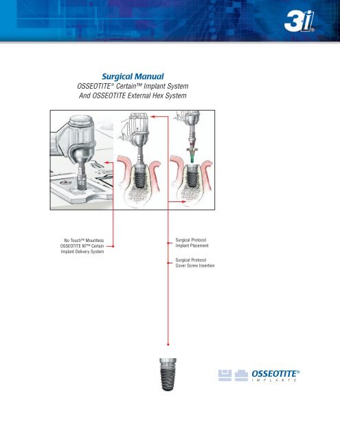
<strong>Surgical</strong> <strong>Manual</strong><br />
OSSEOTITE ® Certain Implant System<br />
And OSSEOTITE External Hex System<br />
No Touch Mountless<br />
OSSEOTITE NT Certain<br />
Implant Delivery System<br />
<strong>Surgical</strong> Protocol<br />
Implant Placement<br />
<strong>Surgical</strong> Protocol<br />
Cover Screw Insertion
Table Of Contents<br />
Introduction And Treatment Planning ..........................................................................................2<br />
Preoperative Planning ..................................................................................................................3<br />
Radiographic Marking Balls ..........................................................................................................3<br />
Top-Down Treatment Planning ......................................................................................................4<br />
<strong>Surgical</strong> Precautions ....................................................................................................................5<br />
Cleaning And Sterilization ............................................................................................................6<br />
3i Depth Gauge And Drill Marking System....................................................................................7<br />
OSSEOTITE NT Certain And OSSEOTITE NT Implant Placement Protocol Guide....................8<br />
OSSEOTITE NT Implant Taps ........................................................................................................8<br />
OSSEOTITE ® Certain Implant Placement Protocol ........................................................................9<br />
Implant Placement Protocol Quick Reference<br />
OSSEOTITE NT ..........................................................................................................12<br />
MicroMiniplant (3.25)..............................................................................................13<br />
OSSEOTITE XP ® 3/4....................................................................................................13<br />
Standard Diameter (3.75) ..........................................................................................13<br />
Standard Diameter (4.00) ..........................................................................................14<br />
OSSEOTITE XP 4/5 ....................................................................................................15<br />
OSSEOTITE XP 5/6 ....................................................................................................15<br />
Wide Diameter (5.0) ..................................................................................................16<br />
Wide Diameter (6.0) ..................................................................................................17<br />
OSSEOTITE NT <strong>Surgical</strong> Tray ......................................................................................................18<br />
OSSEOTITE NT Certain And OSSEOTITE NT Implant Crestal Placement Protocol ......................19<br />
OSSEOTITE Parallel Wall Implant <strong>Surgical</strong> Tray ..........................................................................24<br />
OSSEOTITE Certain And OSSEOTITE Implant Crestal Placement Protocol ................................25<br />
Single-Stage Treatment With A Two-Stage Implant System ......................................................30<br />
<strong>Surgical</strong> Indexing For 3i External Hex Implants ..........................................................................31<br />
How To Use The Icon Key:<br />
The icons represent the connection type<br />
of the implant system and both internal<br />
and external connection types are represented<br />
in this manual. In the fully illustrated protocols,<br />
each icon is present by each step. When a dark<br />
blue icon and a light blue icon are present<br />
together, the dark blue indicates which system<br />
is illustrated. When both icons are dark blue,<br />
then both systems are illustrated together.<br />
Icon Key<br />
OSSEOTITE Certain Internal<br />
Connection Implant System:<br />
OSSEOTITE External Hex<br />
Connection Implant System:<br />
OSSEOTITE Certain Internal<br />
and OSSEOTITE External Hex<br />
Connection Implant System:<br />
1
Introduction And<br />
Treatment Planning<br />
This manual was designed to serve as a<br />
reference guide for the dental practitioner to<br />
utilize 3i implants and surgical instruments to<br />
their maximum potential. 3i’s implant system<br />
was developed to meet the diverse needs of the<br />
patient and to offer the practitioner a choice of<br />
surgical techniques customized to meet each<br />
patient’s individual requirements.<br />
3i’s unique designs enable the practitioner to place<br />
implants in edentulous mandibles or maxillae<br />
to serve as support abutments for fixed and<br />
removable bridgework or single tooth crowns<br />
and to provide the stabilization needed for securing<br />
overdentures. 3i’s system uses proven surgical<br />
procedures to properly secure the implant in the<br />
osseous tissue, thus achieving the physiological<br />
phenomenon referred to as osseointegration.<br />
General Information:<br />
This manual will instruct practitioners in the use<br />
of 3i’s implant systems. The success of any dental<br />
implant system depends upon proper use of the<br />
components and instrumentation. This manual<br />
is not intended for use as a substitute for<br />
professional training and experience.<br />
TREATMENT PLANNING<br />
Patient Evaluation And Selection:<br />
Several important factors must be considered when<br />
evaluating a patient prior to implant surgery. The<br />
presurgical evaluation must include a cautious and<br />
detailed assessment of the patient’s general health,<br />
current medical status, medical history, oral hygiene,<br />
motivation and expectations. Factors such as<br />
heavy tobacco use, chewing patterns and alcohol<br />
consumption should also be considered. In addition,<br />
the clinician should determine if the case presents<br />
an acceptable anatomical basis conducive to implant<br />
placement. An extensive intraoral examination should<br />
be undertaken to evaluate the oral cavity for any<br />
potential bone or soft-tissue pathology. The examiner<br />
should also determine the periodontal status of the<br />
remaining teeth, the health of the soft tissue or the<br />
presence of occlusal abnormalities, such as bruxism<br />
or crossbite. The presence of other conditions that<br />
could adversely affect any existing, natural dentition<br />
or healthy tissue surrounding the implant should also<br />
be evaluated.<br />
Diseases of the mucous membrane and connective<br />
tissues, pathologic bone disease and severe<br />
malocclusion could affect the determination of<br />
whether the patient is a suitable implant candidate.<br />
The use of anticoagulants and the existence of<br />
metabolic diseases, such as diabetes, allergies,<br />
chronic renal or cardiac disease and blood dyscrasia<br />
could significantly influence the patient’s ability to<br />
successfully undergo implant procedures.<br />
If the patient’s medical history reveals an existing<br />
condition or signals a potential problem that may<br />
compromise treatment and/or the patient’s wellbeing,<br />
consultation with a physician is recommended.<br />
2
Preoperative Planning<br />
Preoperative Planning:<br />
Proper treatment planning, as well as the selection of<br />
the proper implant length and diameter, are crucial to<br />
the long-term success of the implant and restoration.<br />
Before an implant can be selected, the anatomical<br />
foundation available to receive the implant must be<br />
carefully assessed. Several steps should be taken to<br />
complete the evaluation:<br />
1. Clinical examination of the oral cavity can provide<br />
important information about the health of the soft<br />
tissue at the proposed implant site. Tissue tone<br />
and the state of the superficial tissues should<br />
be evaluated. In addition, the patient should<br />
demonstrate an adequate dimension of attached<br />
mucosa or keratinized tissue at the site selected<br />
for implantation. In partially edentulous cases,<br />
the periodontal status of the remaining dentition<br />
should be assessed and interaction between<br />
the implant restoration and the adjacent<br />
natural dentition should be considered.<br />
2. The bony foundation and ridge need to be clinically<br />
analyzed to ensure the presence of proper<br />
dimensions and the amount of bone for implant<br />
placement. At least one millimeter of bone should<br />
be present at the buccal and lingual aspects<br />
of the implant following placement. During the<br />
planning state, it is useful to measure the existing<br />
bone foundation.<br />
Radiographic Marking Balls (RMB30)<br />
The vertical height of the bone is best determined<br />
radiographically. Accurate measurement of the vertical<br />
dimension on the radiograph facilitates the selection<br />
of the appropriate implant length. This helps avoid<br />
implant placement into the maxillary sinus, the floor<br />
of the nose or the mandibular canal and prevents<br />
perforation of the inferior aspect of the mandible.<br />
Measurements can be made directly on panographic<br />
film using a millimeter ruler. Corrections should be<br />
made for the degree of enlargement produced by the<br />
particular radiographic equipment.<br />
Radiographic marking balls of a known dimension can<br />
be embedded in a plastic template prior to radiographic<br />
examination. Once the radiograph is taken and the metal<br />
marking balls are visible on the image, measurements<br />
can be taken to determine the amount of bone available<br />
for implant placement.<br />
To calculate the distortion factor, a simple<br />
formula can be utilized:<br />
(5 ÷ A) x B = amount of actual bone available.<br />
Formula Key=<br />
• Radiographic marking ball = 5mm in diameter<br />
• A = Size of marking ball image on radiograph<br />
• B = Length in millimeters on the radiograph of<br />
available bone between the crest of the ridge and<br />
the inferior alveolar nerve canal<br />
Example:<br />
A = 6.5mm<br />
B = 14mm<br />
Therefore: (5 ÷ 6.5) x 14 = 10.76mm actual bone available<br />
NOTE: A 2mm margin of safety, from the apical end<br />
of the implant to the adjacent vital structure,<br />
should be considered.<br />
Marking Ball Image<br />
(6.5mm on this radiograph)<br />
Inferior Alveolar<br />
Nerve Canal<br />
A<br />
B<br />
3
Top-Down<br />
Treatment Planning<br />
In its simplest form, top-down treatment planning<br />
refers to a protocol whereby the desired restorative<br />
result is considered first, leading to consideration<br />
of the ideal prosthetic platform and subsequent<br />
implant selection based on bony anatomy.<br />
A top-down treatment planning methodology will<br />
provide maximum biomechanical stability and allow<br />
for soft tissue flaring by utilizing an implant with a<br />
prosthetic platform slightly smaller in diameter than<br />
the emergence diameter of the tooth being replaced.<br />
3i’s wide selection of implants allows clinicians to<br />
match the size of the prosthetic platform to the<br />
restoration it will eventually support, while allowing<br />
for different bone volumes and anatomical features<br />
at the implant site.<br />
Implant and healing abutment selections are based<br />
upon the relationship of several key measurements:<br />
• The emerging dimension of the crown in relation to<br />
the diameter of the prosthetic platform of the implant<br />
• The height and diameter of the intended restoration<br />
at the tissue exit point<br />
• The bone volume at the implant site in relation<br />
to the diameter of the implant body<br />
The Emergence Profile (EP ® ) Healing Abutment<br />
System consists of healing abutments of various<br />
diameters and heights for shaping the soft tissue<br />
to replicate the geometry and gingival contours<br />
of natural dentition.<br />
5/6mm 6mm 4mm 4mm 5mm 3.25mm<br />
5mm<br />
Implant<br />
Prosthetic<br />
Platform<br />
8 8 5 5 5.5 5 7.5<br />
Crown<br />
Diameter<br />
8 9 5 5 5.5<br />
4<br />
3.5<br />
5/6mm 6mm 4mm 4mm 4/5mm<br />
4mm<br />
3.25mm<br />
4
<strong>Surgical</strong> Precautions<br />
Clinical Considerations<br />
True bone contours can only be evaluated after<br />
tissue flaps have been reflected at the time of<br />
surgery. Even if bone dimensions are painstakingly<br />
measured prior to surgery, the doctor and patient<br />
must accept the possibility that inadequate bone<br />
anatomy might be discovered during surgery and<br />
preclude implant placement.<br />
During the presurgical planning phase, it is<br />
important to determine the vertical dimension - the<br />
actual space available between the alveolar crest and<br />
the opposing dentition - to confirm that the available<br />
space will accommodate the proposed abutment and<br />
the final crown restoration. The height required by<br />
the abutment may vary with the type of abutment;<br />
therefore, the surgeon and restorative dentist should<br />
carefully evaluate the abutment size. The final<br />
prosthesis should be designed prior to the<br />
placement of the implant.<br />
Study models should be used preoperatively to<br />
evaluate the residual ridge and to determine the<br />
position and angulation of all implants. These models<br />
allow the clinician to evaluate the opposing dentition<br />
and its effect on the implant position. A surgical<br />
guide stent, which is critical for determining the<br />
precise position and angulation of the implant, can<br />
be constructed on the study model.<br />
NT Shaping Drill out of the osteotomy, whereupon the<br />
bone particles can be collected.<br />
Bone surgery utilizes a high-torque electric drilling<br />
unit that can be operated in forward and reverse<br />
modes at speeds ranging from 0 to 1,500 rpm,<br />
depending on the surgical requirements. Sharp<br />
instruments of the highest quality should be utilized<br />
during implant site preparation to reduce possible<br />
overheating and trauma of the bone. Minimizing<br />
trauma enhances the potential for successful<br />
osseointegration.<br />
The time elapsed between surgical placement of the<br />
implant and final abutment placement is referred to<br />
as the healing period. Healing periods can vary or be<br />
modified, depending on the quality of the bone at the<br />
implantation site, bony response to the implant surface<br />
and other implanted materials and the surgeon’s<br />
assessment of the patient’s bone density at the time<br />
of the surgical procedure. Extreme care must be<br />
taken to avoid excessive force being applied to the<br />
implant during the healing period.<br />
To prevent damage to the bone tissue and to prevent<br />
compromising osseointegration, abundant and<br />
continuous irrigation with a cool, sterile irrigating<br />
solution is mandatory during all drilling procedures.<br />
The application of excessive pressure during preparation<br />
of the bone site must be avoided.<br />
If the surgeon wishes to collect bone from the site<br />
for bone augmentation while placing an NT Implant,<br />
it is recommended that, once the NT Shaping Drill is<br />
fully advanced into the osteotomy site, stop the drill,<br />
discontinue all irrigation and suction and pull the<br />
5
Cleaning And Sterilization<br />
Single use drills/burs are supplied sterile and<br />
should be properly disposed of after each procedure.<br />
Reusable drills/burs and instrumentation are<br />
supplied nonsterile and must be sterilized prior to<br />
use. Nonsterile items must be removed from the<br />
packaging before sterilization.<br />
Multiple sterilizations may affect the flow of fluid<br />
through internally irrigated drills. The drills should be<br />
checked following each sterilization cycle to determine<br />
if fluid flows through them. Although the surgical<br />
drills are constructed of stainless steel, they should<br />
be adequately dried prior to packaging for sterilization<br />
and again after the sterilization cycle.<br />
To extend the useful life of 3i’s instrumentations,<br />
certain procedures should always be followed:<br />
Cleaning:<br />
1. After use, place drills into a beaker of plain water,<br />
mild soap or specialized cleaning solution.<br />
2. Rinse with tap water for a minimum of two<br />
minutes while brushing with a soft bristled<br />
brush to remove visible debris. Clean the<br />
interior lumen with a thin wire to remove any<br />
remaining debris.<br />
3. Place instruments in an ultrasonic bath containing<br />
enzymatic detergent for five minutes*. Scrub<br />
the instruments again with a soft bristled brush<br />
and ream interior lumen to remove any<br />
remaining debris.<br />
4. Rinse and flush the instruments for one minute<br />
using tap water.<br />
5. Inspect visually for any remaining bone<br />
fragments or debris and scrub as necessary.<br />
Sterilization:<br />
6. Remove the bur block from the surgical tray.<br />
Scrub the surgical tray and block with a soft<br />
bristled brush and mild soap. Rinse thoroughly.<br />
7. Place the components into the surgical tray and<br />
pour ethyl alcohol (do not use rubbing alcohol)<br />
over the burs and tray to remove soap residue<br />
and minerals from the water. This step is<br />
important to help prevent corrosion and<br />
spotting.<br />
8. Wrap the surgical tray in paper or autoclaveapproved<br />
bags twice to prevent a tear of the<br />
outer packaging from contaminated instruments.<br />
9. Steam gravity sterilize for forty minutes at a<br />
temperature of 270˚ - 275˚F (132˚ - 135˚C).<br />
Notes:<br />
1. Multiple sterilizations may affect the flow of fluid<br />
through internally irrigated burs. After each use,<br />
ream the burs individually with wire to remove<br />
any bone fragments or debris that will prevent<br />
the flow of water. This is done prior to the<br />
sterilization cycle.<br />
2. Do not remove drills, instrumentation or surgical<br />
tray from the autoclave until the “dry cycle” is<br />
complete. Very Important!<br />
3. These guidelines DO NOT apply to the cleaning<br />
and sterilization of your powered instrumentation.<br />
Please follow your powered instrumentation<br />
manufacturer’s instructions.<br />
Please refer to ART630 for complete instructions on<br />
the sterilization and care of stainless steel.<br />
*ENZOL enzymatic detergent was used to validate this process, per the<br />
manufacturer’s dilution recommendation.<br />
6
3i Depth Gauge And<br />
Drill Marking System<br />
The 3i depth measurement system provides a mark<br />
on the drill that corresponds to the placement of the<br />
implant within a historical procedure. 3i’s original<br />
protocol follows the principles of protecting the<br />
implant from premature loading by placing the<br />
implant Sub-Crestally.<br />
The drill depth markings do not indicate implant<br />
lengths. Rather, the markings represent the length<br />
of the implant with the cover screw in place.<br />
As a result, to place an implant and cover screw<br />
Sub-Crestally requires drilling to the middle of the<br />
matching drill line. For Crestal placement, drill half<br />
way before the corresponding mark for the implant<br />
length. For Supra-Crestal placement, the drill mark<br />
should remain above the bone by approximately<br />
1.5mm. Please refer to the following chart for<br />
further information.<br />
Crest<br />
of Bone<br />
Tip Dimensions<br />
Drill Diameter<br />
Drill Tip<br />
2.00mm<br />
.6mm<br />
2.30mm<br />
.7mm<br />
2.75mm<br />
.9mm<br />
3.00mm<br />
.9mm<br />
3.15mm<br />
1.0mm<br />
3.25mm<br />
1.0mm<br />
4.25mm<br />
.4mm<br />
5.25mm<br />
.5mm<br />
Note: A drill extension for areas of limited access is available.<br />
2.00mm<br />
TWIST DRILL<br />
DEPTH<br />
GAUGE<br />
IMPLANT W/<br />
COVER SCREW<br />
OSSEOTITE NT<br />
Implant Length<br />
(Label)<br />
Actual<br />
OSSEOTITE NT<br />
Length<br />
Parallel Sided<br />
Implant Length<br />
(Label)<br />
Actual Parallel<br />
Sided Implant<br />
Length<br />
Cover Screw Height<br />
Actual Drill Length<br />
to Mark*<br />
7.0mm 6.6mm 1.0mm 7.6mm<br />
8.5mm 8.1mm 8.5mm 8.1mm 1.0mm 9.1mm<br />
10.0mm 9.6mm 10.0mm 9.6mm 1.0mm 10.6mm<br />
11.5mm 11.1mm 11.5mm 11.1mm 1.0mm 12.1mm<br />
13.0mm 12.6mm 13.0mm 12.6mm 1.0mm 13.6mm<br />
15.0mm 14.6mm 15.0mm 14.6mm 1.0mm 15.6mm<br />
18.0mm 17.6mm 1.0mm 18.6mm<br />
20.0mm 19.6mm 1.0mm 20.6mm<br />
* From point on drill at which maximum diameter starts. (Drill mark is .5mm wide) Drill length listed in chart does not include drill tip.<br />
Important Information Concerning Countersink Drills<br />
CD500 and CD600<br />
A second depth line has been added to the 5mm and<br />
6mm diameter Countersink Drills (CD500 & CD600).<br />
The bottom line (closest to the apex) is positioned<br />
where the original, single line has traditionally been.<br />
The top line (closest to the shank) has been added to<br />
accommodate the new OSSEOTITE ® Certain Implant.<br />
Sub-Crestal<br />
Implant Placement<br />
Crestal<br />
Implant Placement<br />
3i External<br />
Hex Implant<br />
3i OSSEOTITE<br />
Certain Implant<br />
3i External<br />
Hex Implant<br />
3i OSSEOTITE<br />
Certain Implant
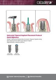
OSSEOTITE NT Certain And<br />
OSSEOTITE NT Implant<br />
Placement Protocol<br />
SUB-CRESTAL Placement:<br />
Drill to the second line on the appropriate shaping<br />
drill (indicated as a solid line in the illustration). Place<br />
the implant to the groove on the implant mount to<br />
properly locate the top of the cover screw at the<br />
crest of the bone.<br />
CRESTAL Placement:<br />
Drill to the first line on the appropriate shaping drill<br />
(indicated as a green line in the illustration). Place the<br />
implant to the juncture of the implant mount and the<br />
implant platform to properly locate the implant at the<br />
crest of the bone.<br />
SUPRA-CRESTAL Placement:<br />
Drill to the first notch on the appropriate shaping<br />
drill (indicated as the dotted line in the illustration).<br />
This will position the seating surface of the implant<br />
1.25mm above the bone.<br />
When placing the OSSEOTITE NT Implant, it is<br />
typical for the implant to advance into the osteotomy<br />
approximately 40 to 50 percent, depending on the<br />
length of the implant being placed, before coming into<br />
contact with the prepared osteotomy. This is a<br />
normal feature of the tapered implant and does not<br />
prevent it from obtaining ideal primary stability<br />
when fully seated.<br />
OSSEOTITE NT Implant Taps:<br />
When placing an OSSEOTITE NT Implant into dense<br />
bone, it may be necessary to tap the osteotomy prior<br />
to implant placement.<br />
The OSSEOTITE NT Implant Taps are all 8.5mm in<br />
length and are designed to tap the coronal aspect of<br />
the osteotomy. For both crestal and sub-crestal<br />
OSSEOTITE NT Implant placement, the tap is<br />
advanced into the osteotomy until the junction of<br />
the colored mount and the tap body is level with the<br />
crest of the bone. The recommended speed for<br />
tapping is 15-20 rpm.<br />
8.5mm<br />
Osteotomy<br />
OSSEOTITE NT Certain<br />
OSSEOTITE NT<br />
11mm<br />
Osteotomy<br />
13mm<br />
Osteotomy<br />
Sub-Crestal<br />
Crestal<br />
Supra-Crestal<br />
Sub-Crestal<br />
Crestal<br />
Supra-Crestal<br />
8
OSSEOTITE ® Certain Implant<br />
Placement Protocol<br />
Sub-Crestal Placement Of The 4mm<br />
OSSEOTITE Certain Implant:<br />
Two-Stage Surgery<br />
When placing the 4mm OSSEOTITE Certain Implant<br />
sub-crestally, the flare created by the countersink<br />
determines where the cover screw will ultimately seat.<br />
For sub-crestal placement, drill the countersink to the<br />
top of the laser line.<br />
Place the OSSEOTITE Certain Implant so that the top<br />
of the cover screw replica on the Certain Implant<br />
Driver is even with the crest.<br />
Note: If the implant is placed too deeply, the cover<br />
screw may not seat completely, leaving a gap.<br />
To correct the gap between the cover screw and the<br />
implant, first remove the cover screw and try one or<br />
all of the following:<br />
• Back out the implant to the proper height<br />
• Remove the interfering crestal bone using either:<br />
- The bone profiling pin (IBPGP) with the<br />
4.0 – 5.0mm bone profiler (BP450)<br />
or<br />
- The round drill (RD100) (Avoid contact with<br />
the implant.)<br />
Sub-crestal OSSEOTITE Certain<br />
implant placement<br />
Certain cover<br />
screw seated<br />
Anatomy Of The Certain Implant<br />
Placement Driver, IIPDTL Or IIPTDTS<br />
The unique design of the Certain Implant Placement<br />
Driver allows it to function as both an implant driver<br />
and a cover screw inserter.<br />
Implant placed too deeply<br />
Depth indicators:<br />
4mm<br />
3mm<br />
2mm<br />
1mm<br />
0mm<br />
Gap between cover screw<br />
and implant<br />
Implant hex<br />
orientation<br />
Cover screw<br />
replica<br />
Implant pick up and insertion hex<br />
O-ring<br />
Cover screw pick up and insertion tip<br />
IIPDTS/L<br />
9
OSSEOTITE ® Certain Implant<br />
Placement Protocol (Continued)<br />
Pick Up And Delivery Of The OSSEOTITE<br />
Certain Implant<br />
Care must be taken when inserting the Implant<br />
Placement Driver tip into the implant. A very low<br />
RPM must be used as you approach the internal<br />
connection of the implant with the driver tip to<br />
properly align the internal hex of the implant with<br />
the external hex of the driver. Press down firmly<br />
to engage the implant securely.<br />
Hex<br />
Implant and driver hex design<br />
Pick Up And Delivery Of The Certain Implant Cover<br />
Screw Or Healing Abutment<br />
The .048 inch tip of the Certain Implant Placement<br />
Driver can be used to pick up and place the cover<br />
screw or the healing abutment. When placing the<br />
cover screw, lower the torque on the drill unit<br />
to 10Ncm.<br />
Implant pick up<br />
The cover screw replica portion of the driver<br />
allows for visual verification of the cover screw<br />
position, making sub-crestal and<br />
crestal placement of the implant predictable.<br />
Cover screw pick up<br />
Sub-Crestal Placement<br />
Crestal Placement<br />
10
OSSEOTITE ® Certain Implant<br />
Placement Protocol (Continued)<br />
Two-Piece Bone Profiling Pin (IBPGP)<br />
The OSSEOTITE Certain Implant<br />
requires a dedicated Bone Profiling<br />
Pin, which is used with the existing<br />
EP ® Bone Profilers. This new<br />
two-piece design allows the pin<br />
to engage the internal hex of the<br />
implant. The hex engagement<br />
prevents the pin from tightening<br />
into the implant during profiling,<br />
making it easy to remove.<br />
Lubricating the top of the pin with an<br />
Two-Piece<br />
Bone Profiler Pin<br />
appropriate lubricant, such as tetracycline ointment,<br />
is recommended. Do not exceed 50 RPM<br />
when using the Bone Profilers.<br />
EP Healing Abutments<br />
A two-piece Bone Profiling Pin (IBPGP) and<br />
corresponding EP Bone Profilers are available to<br />
contour the bone that is to receive the EP Healing<br />
Abutment. These tools are especially helpful in a<br />
single-stage surgical protocol when the implant is<br />
placed sub-crestally.<br />
If the implant is placed sub-crestally and use of an EP<br />
Healing Abutment is indicated, the coronal aspect of<br />
the osteotomy must be prepared to receive the flare<br />
of the EP Healing Abutment.<br />
Bone Profiling Technique:<br />
• EP Bone Profiler slides over<br />
the two-Piece Bone Profiler<br />
Pin.<br />
• EP Bone Profiler creates a<br />
flare in the crest of bone.<br />
• Flare of EP Abutment matches<br />
the flare of the corresponding<br />
EP Bone Profiler.<br />
EP Bone Profilers correspond to sizes of EP Healing Abutments<br />
• EP Healing Abutment seated<br />
properly onto the implant in<br />
sub-crestal placement.<br />
Note:<br />
Non-EP, straight healing abutments and impression<br />
copings are available if bone profiling is not<br />
preferred at either stage 1 or stage 2 surgery.<br />
11
Implant Placement Protocol<br />
Quick Reference<br />
OSSEOTITE NT Certain Implant<br />
Crestal Placement<br />
2.0 or 2.3mm<br />
Twist Drill<br />
PD100<br />
(OPTIONAL)<br />
3.25<br />
NTSD32XX<br />
4.0<br />
NTSD4XX<br />
5.0<br />
NTSD5XX<br />
6.0<br />
NTSD6XX<br />
Round Drill<br />
RD100<br />
Internal<br />
Connection<br />
OSSEOTITE NT Implant<br />
Crestal Placement<br />
2.0 or 2.3mm<br />
Twist Drill<br />
PD100<br />
(OPTIONAL)<br />
INT32XX INT4XX INT5XX INT6XX<br />
3.25<br />
NTSD32XX<br />
4.0<br />
NTSD4XX<br />
5.0<br />
NTSD5XX<br />
6.0<br />
NTSD6XX<br />
Note:<br />
Sequential NT shaping<br />
drills are recommended<br />
up to the final diameter<br />
of the OSSEOTITE NT<br />
implant to be placed.<br />
Note:<br />
When placing a 3.25mm<br />
OSSEOTITE NT Implant,<br />
an Initial Twist Drill<br />
with a maximum<br />
diameter of 2.0mm<br />
is recommended.<br />
Round Drill<br />
RD100<br />
External Hex<br />
Connection<br />
NT32XX NT4XX NT5XX NT6XX<br />
12
Implant Placement Protocol<br />
Quick Reference<br />
OSSEOTITE ® MicroMiniplant Implant<br />
Crestal Placement<br />
2.0 or 2.3mm<br />
Twist Drill<br />
Pilot Drill<br />
PD100<br />
3.0mm<br />
Twist Drill<br />
Round Drill<br />
RD100<br />
Internal<br />
Connection<br />
External Hex<br />
Connection<br />
3.25mm<br />
OSSEOTITE XP ® 3/4 Or ST 3.75mm Implant<br />
Crestal Placement<br />
2.0 or 2.3mm<br />
Twist Drill<br />
Pilot Drill<br />
PD100<br />
3.0mm<br />
Twist Drill<br />
C’sink Drill<br />
CD100<br />
Round Drill<br />
RD100<br />
External Hex<br />
Connection<br />
XP 3/4mm<br />
ST 3.75mm<br />
13
Implant Placement Protocol<br />
Quick Reference<br />
OSSEOTITE ® Certain 4mm Implant<br />
Crestal Placement<br />
2.0 or 2.3mm<br />
Twist Drill<br />
Pilot Drill<br />
PD100<br />
3.0 or 3.25mm<br />
Twist Drill<br />
C’sink Drill<br />
ICD100<br />
Round Drill<br />
RD100<br />
Internal<br />
Connection<br />
4.0mm<br />
OSSEOTITE 4mm Implant<br />
Crestal Placement<br />
2.0 or 2.3mm<br />
Twist Drill<br />
Pilot Drill<br />
PD100<br />
3.0 or 3.25mm<br />
Twist Drill<br />
C’sink Drill<br />
CD100<br />
Round Drill<br />
RD100<br />
External Hex<br />
Connection<br />
4.0mm<br />
14
Implant Placement Protocol<br />
Quick Reference<br />
OSSEOTITE XP ® 4/5mm Implant<br />
Crestal Placement<br />
2.0 or 2.3mm<br />
Twist Drill<br />
Pilot Drill<br />
PD100<br />
3.0 or 3.25mm<br />
Twist Drill<br />
4/5 C’sink Drill<br />
CD4500<br />
Round Drill<br />
RD100<br />
External Hex<br />
Connection<br />
XP 4/5<br />
OSSEOTITE XP 5/6mm Implant<br />
Crestal Placement<br />
2.0 or 2.3mm<br />
Twist Drill<br />
Pilot Drill<br />
PD100<br />
3.0mm<br />
Twist Drill<br />
5mm Pilot/C’sink<br />
CD500<br />
4.25mm<br />
Twist Drill<br />
5/6mm Pilot/C’sink<br />
CD5600<br />
Round Drill<br />
RD100<br />
External Hex<br />
Connection<br />
XP 5/6mm<br />
15
Implant Placement Protocol<br />
Quick Reference<br />
OSSEOTITE ® Certain 5mm Implant<br />
Crestal Placement<br />
2.0 or 2.3mm<br />
Twist Drill<br />
Pilot Drill<br />
PD100<br />
3.0mm<br />
Twist Drill<br />
5mm Pilot/C’sink<br />
CD500<br />
4.25mm<br />
Twist Drill<br />
Round Drill<br />
RD100<br />
Internal<br />
Connection<br />
Wide 5.0mm<br />
OSSEOTITE 5mm Implant<br />
Crestal Placement<br />
2.0 or 2.3mm<br />
Twist Drill<br />
Pilot Drill<br />
PD100<br />
3.0mm<br />
Twist Drill<br />
5mm Pilot/C’sink<br />
CD500<br />
4.25mm<br />
Twist Drill<br />
Round Drill<br />
RD00<br />
External Hex<br />
Connection<br />
Wide 5.0mm<br />
16
Implant Placement Protocol<br />
Quick Reference<br />
OSSEOTITE ® Certain 6mm Implant<br />
Crestal Placement<br />
2.0 or 2.3mm<br />
Twist Drill<br />
Pilot Drill<br />
PD100<br />
3.0mm<br />
Twist Drill<br />
5mm Pilot/C’sink<br />
CD500<br />
4.25mm<br />
Twist Drill<br />
6mm Pilot/C’sink<br />
CD600<br />
5.25mm<br />
Twist Drill<br />
Round Drill<br />
RD100<br />
Internal<br />
Connection<br />
Wide 6.0mm<br />
OSSEOTITE 6mm Implant<br />
Crestal Placement<br />
2.0 or 2.3mm<br />
Twist Drill<br />
Pilot Drill<br />
PD100<br />
3.0mm<br />
Twist Drill<br />
5mm Pilot/C’sink<br />
CD500<br />
4.25mm<br />
Twist Drill<br />
6mm Pilot/C’sink<br />
CD600<br />
5.25mm<br />
Twist Drill<br />
Round Drill<br />
RD100<br />
External Hex<br />
Connection<br />
Wide 6.0mm<br />
17
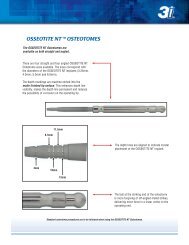
OSSEOTITE NT <br />
<strong>Surgical</strong> Tray<br />
Coordinating the use of the <strong>Surgical</strong> Tray with the<br />
<strong>Surgical</strong> <strong>Manual</strong> illustrations:<br />
The OSSEOTITE NT <strong>Surgical</strong> Tray is numbered to indicate<br />
the appropriate steps of the implant placement protocol.<br />
The following illustrated implant placement protocol uses<br />
the same numbering sequence.<br />
Close-up view of <strong>Surgical</strong> Tray illustrating numbering sequence<br />
18
OSSEOTITE NT Certain<br />
And OSSEOTITE NT Implant<br />
Crestal Placement Protocol<br />
1. Once the implant site has been determined, mark<br />
the site with a Round Drill and penetrate the cortical bone.<br />
Set the drill speed at approximately 1,500 rpm.<br />
• Instruments needed:<br />
Round Drill (RD100)<br />
2a. Proceed with the Initial Twist Drill. Penetrate the<br />
bone at the marked site to the desired depth.<br />
• Instruments needed:<br />
2 or 2.3mm Twist Drill<br />
(ITD215, DT215 or DTN215)<br />
2b. Verify the direction and position of the preparation<br />
by inserting the thin portion of the Direction Indicator into<br />
the osteotomy.<br />
• Instruments needed:<br />
Direction Indicator (DI100 or DI2310)<br />
3. OPTIONAL STEP<br />
Use the Pilot Drill to shape the coronal aspect of<br />
the implant site. Drill to the laser etched depth marking for<br />
placement of an OSSEOTITE NT Implant.<br />
• Instruments needed:<br />
Pilot Drill (PD100)<br />
19
OSSEOTITE NT Certain<br />
And OSSEOTITE NT Implant<br />
Crestal Placement Protocol<br />
4. Final Drilling Step for 3.25mm OSSEOTITE NT Implant<br />
Proceed with the 3.25mm NT Shaping Drill that<br />
is the same length as the OSSEOTITE NT Implant to be<br />
placed (300 rpm is the recommended speed when<br />
using the shaping drill. In dense bone, the speed may<br />
need to be increased to 500 rpm).<br />
• Instruments needed:<br />
3.25mm NT Shaping Drill (NTSD32xx)<br />
• Proceed to step 8a for 3.25mm OSSEOTITE NT<br />
Implant placement<br />
5. Final Drilling Step for 4.0mm OSSEOTITE NT Implant<br />
Continue preparing the osteotomy with the<br />
4mm NT Shaping Drill that is the same length as the<br />
OSSEOTITE NT Implant to be placed (300 rpm is the<br />
recommended speed when using the shaping drill. In<br />
dense bone, the speed may need to be increased to<br />
500 rpm).<br />
• Instruments needed:<br />
4mm NT Shaping Drill (NTSD4xx)<br />
• Proceed to step 8a for 4.0mm OSSEOTITE NT<br />
Implant placement<br />
6. Final Drilling Step for 5.0mm OSSEOTITE NT Implant<br />
Resume preparing the osteotomy with the 5mm<br />
NT Shaping Drill that is the same length as the<br />
OSSEOTITE NT Implant to be placed (300 rpm is the<br />
recommended speed when using the shaping drill. In<br />
dense bone, the speed may need to be increased to<br />
500 rpm).<br />
• Instruments needed:<br />
5mm NT Shaping Drill (NTSD5xx)<br />
• Proceed to step 8a for 5.0mm OSSEOTITE NT<br />
Implant placement<br />
7. Final Drilling Step for 6.0mm OSSEOTITE NT Implant<br />
Finish preparing the osteotomy with the 6mm<br />
NT Shaping Drill that is the same length as the<br />
OSSEOTITE NT Implant to be placed (300 rpm is the<br />
recommended speed when using the shaping drill. In<br />
dense bone, the speed may need to be increased to<br />
500 rpm).<br />
• Instruments needed:<br />
6mm NT Shaping Drill (NTSD6xx)<br />
• Proceed to step 8a for 6.0mm OSSEOTITE NT<br />
Implant placement<br />
20
OSSEOTITE NT Certain<br />
And OSSEOTITE NT Implant<br />
Crestal Placement Protocol<br />
8a. No-Touch Delivery System<br />
Remove contents from the implant box.<br />
8b. Nonsterile assistant should peel back the tray<br />
lid and drop the No-Touch Implant Tray onto the<br />
sterile drape.<br />
8c. Place the No-Touch Implant Tray into the appropriate<br />
location on the surgical tray.<br />
8d. Peel back the tray lid to expose the implant and<br />
cover screw.<br />
21
OSSEOTITE NT Certain<br />
And OSSEOTITE NT Implant<br />
Crestal Placement Protocol<br />
9. Pick up the implant from the surgical tray using<br />
the Certain Implant Placement Driver Tip<br />
(IIPDTS or IIPDTL).<br />
or<br />
Pick up the implant from the surgical tray using<br />
the Handpiece Connector (MDR10).<br />
Carry the implant to the mouth facing upward to<br />
prevent accidental dislodging.<br />
10. Place the implant in the prepared site at about<br />
15 to 20 RPM. The Spiral ICE design will allow smooth<br />
and precise implant placement without tapping in all but<br />
the most dense bone.<br />
• Instruments needed:<br />
Certain Implant Placement Driver Tip<br />
(IIPDTS or IIPDTL)<br />
or<br />
Handpiece Connector (MDR10)<br />
11. To remove the Certain Implant Placement Driver<br />
Tip (IIPDTS or IIPDTL) from the implant, pull straight up<br />
and out.<br />
or<br />
To remove the implant mount, place the Open-<br />
End Wrench onto the mount. Loosen the screw at the<br />
top of the mount with a Large Hex Driver or the Large<br />
Hex Driver Tip inserted into the Right-Angle Driver and<br />
rotate counter-clockwise. After the screw is loosened,<br />
rotate the Open-End Wrench counterclockwise slightly<br />
before removing the mount. The mount may be carried<br />
from the mouth with the Open-End Wrench.<br />
• Instruments needed:<br />
Open-End Wrench (CW100),<br />
Large Hex Driver Tip (RASH3),<br />
Right-Angle Driver (CATDB with CADD1),<br />
or Large Hex Driver (PHD02N)<br />
22
OSSEOTITE NT Certain<br />
And OSSEOTITE NT Implant<br />
Crestal Placement Protocol<br />
12. Pick up the cover screw from the No-Touch<br />
Implant Tray with:<br />
the internal connection implant driver (IIPDTS or<br />
IIPDTL) and place onto the implant.<br />
or<br />
the Small Hex Driver (PHD00N) or the Cover<br />
Screw Inserter (CSI10) and place onto the implant. The<br />
Cover Screw Inserter is used for Cover Screws 4.5mm in<br />
diameter only, while the Small Hex Driver may be used for the<br />
3.5mm, 4.5mm, 5mm and 6mm Cover Screws. Final hand<br />
tightening of the cover screw should be done with the<br />
Small Hex Driver.<br />
13. Close tissue and suture.<br />
23
OSSEOTITE ® Parallel Wall Implant<br />
<strong>Surgical</strong> Tray<br />
Coordinating the use of the <strong>Surgical</strong> Tray<br />
with the <strong>Surgical</strong> <strong>Manual</strong> illustrations:<br />
The OSSEOTITE Parallel Wall Implant <strong>Surgical</strong><br />
Tray is numbered to indicate the appropriate<br />
steps of the implant placement protocol. The<br />
following illustrated implant placement protocol<br />
uses the same numbering sequence.<br />
24<br />
Close-up view of <strong>Surgical</strong> Tray illustrating numbering sequence
OSSEOTITE ® Certain<br />
And OSSEOTITE Implant<br />
Crestal Placement Protocol<br />
For A 6mm Diameter Implant<br />
The drilling protocol for the Crestal Placement of the 6mm<br />
OSSEOTITE Certain and OSSEOTITE Implant was chosen<br />
as a representative protocol to provide a detailed implant<br />
placement synopsis. For the drilling protocol specific to<br />
implant diameter and design, please refer to the Implant<br />
Placement Protocol Quick Reference section of this manual.<br />
1. Once the implant site has been determined, mark<br />
the site with a Round Drill and penetrate the cortical bone.<br />
Set the drill speed at approximately 1,500 RPM.<br />
• Instruments needed:<br />
Round Drill (RD100)<br />
2a. Proceed with the Initial Twist Drill. Penetrate the<br />
bone at the marked site to the desired depth.<br />
• Instruments needed:<br />
2 or 2.3mm Twist Drill<br />
(ITD215, DT215 or DTN215)<br />
2b. Verify the direction and position of the preparation<br />
by inserting the thin portion of the Direction Indicator into<br />
the osteotomy.<br />
• Instruments needed:<br />
Direction Indicator (DI100 or DI2310)<br />
25
OSSEOTITE ® Certain<br />
And OSSEOTITE Implant<br />
Crestal Placement Protocol<br />
For A 6mm Diameter Implant<br />
3. Use the Pilot Drill to shape the coronal aspect<br />
of the implant site. Drill to the laser etched depth<br />
marking for placement of an OSSEOTITE Implant.<br />
• Instruments needed:<br />
Pilot Drill (PD100)<br />
4. Once proper alignment is verified using the<br />
Direction Indicator, proceed with the 3.00mm Twist Drill<br />
to the desired depth.<br />
• Instruments needed:<br />
3.00mm Twist Drill (ITD315)<br />
5. Use the first cutting groove on the 5.00mm<br />
Pilot Countersink Drill to widen the coronal aspect of<br />
the osteotomy to allow the 4.25mm Twist Drill to enter<br />
the osteotomy.<br />
• Instruments needed:<br />
5mm Pilot Countersink Drill (CD500)<br />
6. Once the coronal aspect of the osteotomy has<br />
been piloted, proceed with the 4.25mm Twist Drill to the<br />
desired depth.<br />
• Instruments needed:<br />
4.25mm Twist Drill (ITD423)<br />
26
OSSEOTITE ® Certain<br />
And OSSEOTITE Implant<br />
Crestal Placement Protocol<br />
For A 6mm Diameter Implant<br />
7. Advance the 6.00mm Pilot Countersink drill all<br />
the way to the laser marking. This will countersink the<br />
implant and allow for crestal placement of the OSSEOTITE<br />
Certain implant.<br />
or<br />
Advance the 6.00mm Pilot Countersink drill to the<br />
first cutting groove. This will countersink the External Hex<br />
OSSEOTITE implant and allow for crestal placement.<br />
• Instrument needed:<br />
6.00mm Pilot Countersink Drill (CD600)<br />
8. Once the coronal aspect of the osteotomy has<br />
been piloted, proceed with the 5.25mm Twist Drill to the<br />
desired depth. The recommended speed for a 5.25mm<br />
Twist Drill is 900 RPM.<br />
• Instrument needed:<br />
5.25mm Twist Drill (ITD523)<br />
9a. No-Touch Delivery System<br />
Remove contents from the implant box.<br />
9b. A nonsterile assistant should peel back the tray lid<br />
and drop the No-Touch Implant Tray onto the sterile<br />
drape.<br />
27
OSSEOTITE ® Certain<br />
And OSSEOTITE Implant<br />
Crestal Placement Protocol<br />
For A 6mm Diameter Implant<br />
9c. Place the No-Touch Implant Tray into the<br />
appropriate location on the surgical tray.<br />
9d. Peel back the tray lid to expose the implant and<br />
cover screw.<br />
10. Pick up the implant from the surgical tray using<br />
the Certain Implant Placement Driver Tip<br />
(IIPDTS or IIPDTL) .<br />
or<br />
Pick up the implant from the surgical tray using<br />
the Handpiece Connector (MDR10).<br />
Carry the implant to the mouth facing upward to<br />
prevent accidental dislodging.<br />
11. Place the implant in the prepared site at about<br />
15 to 20 RPM. The ICE ® design will allow smooth and<br />
precise implant placement without tapping in all but the<br />
most dense bone.<br />
28
OSSEOTITE ® Certain<br />
And OSSEOTITE Implant<br />
Crestal Placement Protocol<br />
For A 6mm Diameter Implant<br />
12. To remove the Certain Implant Placement Driver<br />
Tip (IIPDTS or IIPDTL) from the implant, pull straight up<br />
and out.<br />
or<br />
To remove the implant mount, place the Open-End<br />
Wrench onto the mount. Loosen the screw at the top of the<br />
mount with a Large Hex Driver or the Large Hex Driver Tip<br />
inserted into the Right-Angle Driver and rotate counterclockwise.<br />
After the screw is loosened, rotate the Open-End<br />
Wrench counterclockwise slightly before removing the<br />
mount. The mount may be carried from the mouth with the<br />
Open-End Wrench.<br />
• Instruments needed:<br />
Open-End Wrench (CW100), Large Hex Driver Tip<br />
and Right-Angle Driver (RASH3 and CATDB with CADD1),<br />
or a Large Hex Driver (PHD02N)<br />
13. Pick up the cover screw from the No-Touch<br />
Implant Tray with:<br />
the internal connection implant driver (IIPDTS or<br />
IIPDTL) and place onto the implant.<br />
or<br />
the Small Hex Driver (PHD00N) or the Cover<br />
Screw Inserter (CSI10) and place onto the implant. The<br />
Cover Screw Inserter is used for Cover Screws 4.5mm in<br />
diameter only, while the Small Hex Driver may be used for the<br />
3.5mm, 4.5mm, 5mm and 6mm Cover Screws. Final hand<br />
tightening of the cover screw should be done with the<br />
Small Hex Driver.<br />
14. Close tissue and suture.<br />
29
Single-Stage Treatment With<br />
A Two-Stage Implant System<br />
Several advantages can be realized by utilizing a two-stage<br />
implant system in a single-stage treatment protocol.<br />
Attaching a one-piece or two-piece healing abutment<br />
immediately following implant placement eliminates the need<br />
for a second-stage surgery. Eliminating the second surgical<br />
procedure reduces trauma and decreases treatment time, while<br />
the two-stage implant design maintains restorative flexibility.<br />
1. After the implant is fully seated in the osteotomy,<br />
remove the implant mount from the external hex implant.<br />
2. Select the appropriate one-piece healing<br />
abutment depending upon the implant seating surface,<br />
tissue depth and desired EP ® dimension.<br />
or<br />
Select the appropriate one or two-piece healing<br />
abutment depending upon the implant seating surface,<br />
tissue depth and desired EP dimension.<br />
Bone profiling of the osteotomy may be<br />
necessary to fully seat the healing abutment onto<br />
the implant.<br />
3. Tighten the one or two-piece healing abutment<br />
Screw to 20Ncm and suture the soft tissue around the<br />
healing abutment.<br />
30
<strong>Surgical</strong> Indexing For<br />
3i External Hex Implants<br />
By indexing the external hex implant after placement using<br />
a <strong>Surgical</strong> Index Coping, a provisional restoration can be<br />
fabricated in the laboratory while the bone and soft tissues are<br />
healing. The <strong>Surgical</strong> Index Coping screws into the implant and<br />
registers the orientation of the implant hex.<br />
The Index Coping is then transferred to the guide stent. The<br />
implant analog is mated to the Index Coping and secured in the<br />
preoperative stone model.<br />
1. Align and attach the index coping with the<br />
implant hex and attach the coping to the guide stent with<br />
cold-cure acrylic resin.<br />
2. Unscrew the index coping from the implant<br />
and remove the guide stent and index coping assembly.<br />
3. Mate the implant analog with the index coping and<br />
attached guide stent.<br />
31
<strong>Surgical</strong> Indexing For<br />
3i External Hex Implants<br />
4. Prepare the stone model using a large round<br />
bur to allow space for insertion of implant analog.<br />
5. Secure implant analog in the stone model<br />
using a cold-cure acrylic resin or dental stone and then<br />
remove the guide stent and index coping.<br />
• Instruments needed:<br />
<strong>Surgical</strong> Index Coping (IC100)<br />
32
Implant Innovations, Inc.<br />
Global Headquarters<br />
4555 Riverside Drive<br />
Palm Beach Gardens, FL 33410<br />
1.800.342.5454<br />
Outside U.S.: + 561.776.6700<br />
Fax: + 561.776.1272<br />
www.3i-online.com<br />
3i and design, OSSEOTITE, OSSEOTITE XP, EP and ICE are registered trademarks and<br />
OSSEOTITE NT, Microminiplant, No Touch, Spiral Ice and Certain are trademarks of<br />
Implant Innovations, Inc. © 2003 Implant Innovations, Inc. All rights reserved.<br />
CATSM<br />
REV C 11/03<br />
SUBSIDIARIES<br />
BRAZIL<br />
Phone: +55-11-5081-4405<br />
Fax: +55-11-5081-7484<br />
SPAIN<br />
Phone: +34-93-470-59-50<br />
Fax: +34-93-372-11-25<br />
AUSTRIA<br />
Wieladent<br />
Phone: +43-7672-93901<br />
Fax: +43-7672-93903<br />
EL SALVADOR<br />
Dentimerc SA de CV<br />
Phone: +503-263-6350<br />
Fax: +503-263-6676<br />
KOREA<br />
Jungsan Biomed Corp.<br />
Phone: +82-2-516-1808<br />
Fax: +82-2-514-9434<br />
SINGAPORE<br />
Asia Implant Support & Services<br />
Phone: +65-6223-3229<br />
Fax: +65-6220-3538<br />
CANADA<br />
Phone: +514-956-9843<br />
Fax: +514-956-9844<br />
FRANCE<br />
Phone: +33-1-41054343<br />
Fax: +33-1-41054340<br />
GERMANY<br />
Phone: +49-721-6314-220<br />
Fax: +49-721-6314-233<br />
MEXICO<br />
Phone: +52-55-5679-1619<br />
Fax: +52-55-5684-8098<br />
SWITZERLAND<br />
Phone: +41-1-3804646<br />
Fax: +41-1-3834655<br />
U.K.<br />
Phone: +44-1628-829314<br />
Fax: +44-1628-820182<br />
DISTRIBUTORS<br />
ARGENTINA<br />
<strong>Dental</strong>max, SA<br />
Phone: +541-1482-71001<br />
Fax: +541-1482-67373<br />
BENELUX<br />
Titamed, NV<br />
Phone: +32-2-5410290<br />
Fax: +32-2-5410291<br />
CHILE<br />
Cybel, SA<br />
Phone: +56-2-2321883<br />
Fax: +56-2-2330176<br />
COLOMBIA<br />
Implantes y Componentes<br />
Phone: +571-612-9362<br />
Fax: +571-620-5450<br />
GREECE<br />
Kostas Kornisorlis and Co.<br />
Phone: +302310-269-079<br />
Fax: +302310-555-573<br />
ISRAEL<br />
H.A. Systems<br />
Phone: +972-3-6138777<br />
Fax: +972-3-6138778<br />
ITALY<br />
Biomax, srl.<br />
Phone: +39-0444-913410<br />
Fax: +39-0444-913695<br />
LEBANON<br />
Tamer Freres s.a.l.<br />
Phone: +961-1-485690<br />
Fax: +961-1-510233<br />
PANAMA<br />
Odontomedica, S.A.<br />
Phone: +507-2-239622<br />
Fax: +507-2-239621<br />
PARAGUAY<br />
Andres H. Arce y Cia SRL<br />
Phone: +595-21-208185<br />
Fax: +595-21-496291<br />
TAIWAN<br />
Kuo Hwa <strong>Dental</strong> Suppliers Co., Ltd.<br />
Phone: +886-2-2226-1770<br />
Fax: +886-2-2226-8747<br />
THAILAND<br />
PT Endeavour Co., Ltd.<br />
Phone: +662-264-2574<br />
Fax: +662-264-2573<br />
UKRAINE<br />
Porcelain Ltd.<br />
Phone: +380-44-246-9679<br />
Fax: +380-44-246-8468<br />
NORDIC REGION<br />
Phone: +46-40-17-6090<br />
Fax: +46-40-17-6099<br />
AUSTRALIA<br />
Rudolf Gunz & Co. Pty., Ltd.<br />
Phone: +61-2-9935-6655<br />
Fax: +61-2-9935-6650<br />
COSTA RICA<br />
Implantec S.A.<br />
Phone: +506-2-256411<br />
Fax: +506-2-247620<br />
JAPAN<br />
Implant Innovations Japan<br />
Phone: +81-66-868-3012<br />
Fax: +81-66-868-2444<br />
POLAND<br />
<strong>Dental</strong> <strong>Depot</strong><br />
Phone: +48-71-341-3091<br />
Fax: +48-71-343-6560<br />
URUGUAY<br />
Jelenko Distribution SRL<br />
Phone: +598-408-3003<br />
Fax: +598-2-7-12-5399