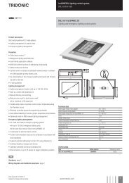
TALEXXconverter LCU 60 W 12/24 V indoor IP20 - Tridonic
TALEXXconverter LCU 60 W 12/24 V indoor IP20 - Tridonic
TALEXXconverter LCU 60 W 12/24 V indoor IP20 - Tridonic

You also want an ePaper? Increase the reach of your titles
YUMPU automatically turns print PDFs into web optimized ePapers that Google loves.
U LED<br />
LED control gear<br />
Uconverter <strong>LCU</strong> <strong>60</strong> W <strong>12</strong>/<strong>24</strong> V <strong>indoor</strong> <strong>IP20</strong><br />
<strong>LCU</strong> <strong>indoor</strong> <strong>IP20</strong><br />
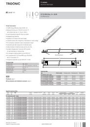
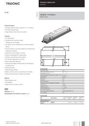
Product description<br />
• Constant voltage LED control gear<br />
• Universal input voltage range<br />
• Constant output voltage<br />
• Nominal life-time up to 50,000 h (at ta 40 °C with a failure rate<br />
max. 0.2 % per 1,000 h)<br />
• 5-year guarantee<br />
• <strong>24</strong> V LED control gear: suitable for emergency installations<br />
according to EN 50172<br />
• Complies with CLASS C from minimum to maximum load range<br />
according to EN 61000-3-2<br />
Properties<br />
• High efficiency<br />
• Low power loss<br />
• Overtemperature and overload protection<br />
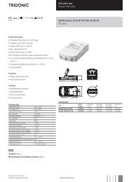
35 45<br />
• Short-circuit shutdown feature with automatic restart<br />
• Protection class II, SELV<br />
• Type of protection <strong>IP20</strong><br />
• Plastic casing white<br />
254<br />
4,2<br />
22,5<br />
230<br />
Technical data<br />
Rated supply voltage<br />
<strong>12</strong>0 – <strong>24</strong>0 V<br />
Input voltage, AC<br />
108 – 264 V<br />
Input voltage, DC 1<br />
<strong>12</strong>0 – 288 V<br />
Rated current (at 230 V 50 Hz)<br />
0.33 A<br />
Mains frequency 1<br />
0 / 50 / <strong>60</strong> Hz<br />
Efficiency > 80 %<br />
λ (at 230 V 50 Hz) 0.93<br />
Output voltage tolerance + 10 %<br />
Output power<br />
<strong>60</strong> W<br />
Output power range<br />
5 – <strong>60</strong> W<br />
Turn on time (output)<br />
≤ 0.5 s<br />
Turn off time (output)<br />
≤ 1 s<br />
Hold on time at power failure (Output)<br />
10 ms<br />
Ambient temperature ta -25 ... +50 °C<br />
Ambient temperature ta (at life-time 50,000 h) -25 ... +40 °C<br />
Storage temperature ts -30 ... +85 °C<br />
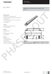
Dimensions LxWxH<br />
254 x 45 x 35 mm<br />
Hole spacing D<br />
230 mm<br />
Ordering data<br />
Type Article number Packaging carton Packaging pallet Weight per pc.<br />
<strong>LCU</strong> 0<strong>60</strong>/<strong>12</strong> E020 <strong>24</strong>166323 20 pc(s). 720 pc(s). 0.5 kg<br />
<strong>LCU</strong> 0<strong>60</strong>/<strong>24</strong> E020 <strong>24</strong>1663<strong>24</strong> 20 pc(s). 720 pc(s). 0.5 kg<br />
Specific technical data<br />
Type Max. casing temperature tc Output voltage Max. input power Output current range Max. output voltage 2<br />
<strong>LCU</strong> 0<strong>60</strong>/<strong>12</strong> E020 75 °C <strong>12</strong> V 75 W 0.4 – 5.0 A 13.2 V<br />
<strong>LCU</strong> 0<strong>60</strong>/<strong>24</strong> E020 75 °C <strong>24</strong> V 75 W 0.2 – 2.5 A 26.4 V<br />
1 DC operation only with <strong>24</strong> V LED control gear.<br />
2 At failure mode (230 V, 50 Hz).<br />
Data sheet 05/15-928-14<br />
Subject to change without notice.<br />
www.tridonic.com 1
U LED<br />
LED control gear<br />
Standards<br />
EN 55015<br />
EN 61000-3-2<br />
EN 61000-3-3<br />
EN 61347-1<br />
EN 61347-2-13<br />
EN 61547<br />
EN 62384<br />
Acc. to 50172: <strong>24</strong> V LED control gear suitable for central battery systems<br />
Overload protection<br />
Automatic shutdown of the LED control gear if the maximum output current is<br />
exceeded. Automatic restart if the output current is below the limit.<br />
No-load operation<br />
The LED control gear is not damaged in the no-load operation. The max. output<br />
voltage (see page1) can be obtained during no-load operation.<br />
Over temperature protection<br />
Automatic shutdown of the LED control gear if the temperature limit is exceeded.<br />
Automatic restart if the temperature falls below the limit.<br />
Glow wire test according to EN <strong>60</strong>695-2-11<br />
850 °C passed.<br />
Maximum loading of automatic circuit breakers<br />
Automatic circuit breaker type C10 C13 C16 C20 B10 B13 B16 B20 Inrush current<br />
Installation Ø 1.5 mm 2 1.5 mm 2 1.5 mm 2 2.5 mm 2 1.5 mm 2 1.5 mm 2 1.5 mm 2 2.5 mm 2 I max<br />
time<br />
<strong>LCU</strong> 0<strong>60</strong>/00<strong>12</strong> E020 10 14 18 22 5 7 9 11 52 A 0.<strong>24</strong> ms<br />
<strong>LCU</strong> 0<strong>60</strong>/00<strong>24</strong> E020 10 14 18 22 5 7 9 11 52 A 0.<strong>24</strong> ms<br />
Harmonic distortion in the mains supply (at 230 V / 50 Hz and full load) in %<br />
Type THD 3 5 7 9 11<br />
<strong>LCU</strong> 0<strong>60</strong>/00<strong>12</strong> E020 8 6 3 3 2 1<br />
<strong>LCU</strong> 0<strong>60</strong>/00<strong>12</strong> E020 7 4 3 2 2 1<br />
<strong>LCU</strong> 0<strong>60</strong>/00<strong>12</strong> E020 – Efficiency versus load<br />
Efficiency [%]<br />
90<br />
85<br />
80<br />
75<br />
70<br />
65<br />
<strong>60</strong><br />
55<br />
50<br />
45<br />
40<br />
<strong>12</strong>0V/<strong>60</strong>Hz<br />
<strong>24</strong>0V/50Hz<br />
10 % 30 % 50 % 75 % 100 %<br />
Load<br />
<strong>LCU</strong> 0<strong>60</strong>/00<strong>12</strong> E020 – PF value versus load<br />
PF<br />
1.1<br />
1.0<br />
0.9<br />
0.8<br />
0.7<br />
0.6<br />
0.5<br />
0.4<br />
0.3<br />
<strong>12</strong>0V/<strong>60</strong>Hz<br />
<strong>24</strong>0V/50Hz<br />
10 % 30 % 50 % 75 % 100 %<br />
Load<br />
<strong>LCU</strong> 0<strong>60</strong>/00<strong>24</strong> E020 – Efficiency versus load<br />
Efficiency [%]<br />
90<br />
85<br />
80<br />
75<br />
70<br />
65<br />
<strong>60</strong><br />
55<br />
50<br />
<strong>12</strong>0V/<strong>60</strong>Hz<br />
<strong>24</strong>0V/50Hz<br />
10 % 30 % 50 % 75 % 100 %<br />
Load<br />
<strong>LCU</strong> 0<strong>60</strong>/00<strong>24</strong> E020 – PF value versus load<br />
PF<br />
1.1<br />
1.0<br />
0.9<br />
0.8<br />
0.7<br />
0.6<br />
0.5<br />
0.4<br />
0.3<br />
<strong>12</strong>0V/<strong>60</strong>Hz<br />
<strong>24</strong>0V/50Hz<br />
10 % 30 % 50 % 75 % 100 %<br />
Load<br />
Data sheet 05/15-928-14<br />
Subject to change without notice.<br />
www.tridonic.com 2
U LED<br />
LED control gear<br />
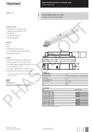
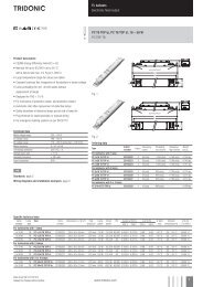
Wiring diagram<br />
L<br />
N<br />
<strong>12</strong>0-<strong>24</strong>0 VAC<br />
Wiring type and cross section<br />
The wiring can be in stranded wires with ferrules or solid. For perfect function of<br />
the screw terminals the strip length should be 7.5–8.5 mm for the terminal.<br />
Max. torque at the clamping screw: 0.5 Nm<br />
Uconverter<br />
<strong>LCU</strong> ... E020<br />
The maximum secondary cable length at the terminals is 2 m. The LED wiring<br />
should be kept as short as possible to ensure good EMC.<br />
Input / Output terminal<br />
Installation instructions<br />
The switching of LEDs on secondary side is not permitted.<br />
A proper functioning of the <strong>LCU</strong> in combination with third party dimming devices<br />
(e.g. PWM) cannot be guaranteed.<br />
Please note that <strong>LCU</strong> 0<strong>60</strong> complies with protection class II so<br />
special measures are needed if it is to be installed in protection class I<br />
applications / luminaires.<br />
Please note the requirements set out in the document<br />
LED_Betriebsgeraete_installationshinweis.pdf<br />
(http://www.tridonic.com/com/de/technische-doku.asp).<br />
PRI and SEC:<br />
Min. Ø = 6,7 mm<br />
Max. Ø = 7,3 mm<br />
7,5 – 8,5 mm<br />
0,5 – 1,5 mm²<br />
Isolation and electric strength testing of luminaires<br />
Electronic devices can be damaged by high voltage. This has to be considered<br />
during the routine testing of the luminaires in production.<br />
According to IEC <strong>60</strong>598-1 Annex Q (informative only!) or ENEC 303-Annex A, each<br />
luminaire should be submitted to an isolation test with 500 V DC for 1 second. This<br />
test voltage should be connected between the interconnected phase and neutral<br />
terminals and the earth terminal.<br />
The isolation resistance must be at least 2 MΩ.<br />
As an alternative, IEC <strong>60</strong>598-1 Annex Q describes a test of the electrical strength<br />
with 1500 V AC (or 1.414 x 1500 V DC). To avoid damage to the electronic devices this<br />
test must not be conducted.<br />
Additional information<br />
Additional technical information at<br />
www.tridonic.com → Technical Data<br />
Guarantee conditions at<br />
www.tridonic.com → Services<br />
No warranty if device was opened.<br />
Data sheet 05/15-928-14<br />
Subject to change without notice.<br />
www.tridonic.com 3