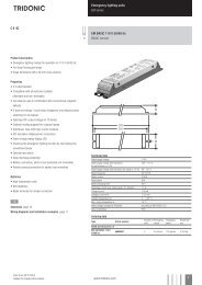
TALEXXconverter LCI 4x16 W 200-400mA lp - Tridonic
TALEXXconverter LCI 4x16 W 200-400mA lp - Tridonic
TALEXXconverter LCI 4x16 W 200-400mA lp - Tridonic

You also want an ePaper? Increase the reach of your titles
YUMPU automatically turns print PDFs into web optimized ePapers that Google loves.
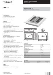
LED control gear<br />
Linear / area fixed output<br />
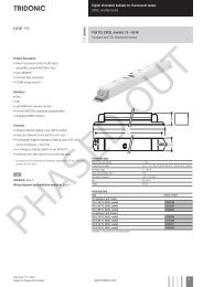
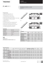
Uconverter <strong>LCI</strong> <strong>4x16</strong> W <strong>200</strong> – 400 mA <strong>lp</strong><br />
TOP series<br />
OUT<br />
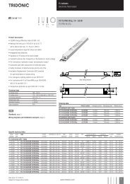
Product description<br />
• Built-in LED control gear for LED<br />
• Constant current LED control gear with <strong>200</strong> – 400 mA output<br />
current<br />
• 1- to 4-channel operation<br />
• Max. output power 67.2 W<br />
• SELV<br />
• Nominal life-time of 50,000 h (at ta 50 °C with a failure rate max.<br />
0.2 % per 1,000 h)<br />
• 5-year guarantee<br />
Properties<br />
• Low-profile metal casing with white cover<br />
• Type of protection IP20<br />
Functions<br />
• Overload protection<br />
• Short circuit proof<br />
• Suitable for emergency lighting units acc. to EN 50172<br />
È<br />
Ordering data<br />
Standards, page 4<br />
Type Article number Packaging carton Packaging pallet Weight per pc.<br />
<strong>LCI</strong> <strong>4x16</strong>W <strong>200</strong>mA-<strong>400mA</strong> <strong>lp</strong> 28000245 10 pc(s). 540 pc(s). 0.24 kg<br />
Technical data<br />
Rated supply voltage<br />
220 – 240 V<br />
AC Voltage range<br />
198 – 264 V<br />
DC Voltage range<br />
176 – 280 V<br />
Mains frequency<br />
0 / 50 / 60 Hz<br />
Typ. rated current (at 230 V / 50 Hz / full load) 0.35 A<br />
Mains current (at 220 V / 0 Hz / full load) 0.35 A<br />
Max. input power<br />
75.8 W<br />
Typ. efficiency (at 230 V / 50 Hz / full load) > 85 %<br />
Typ. λ (at 230 V / 50 Hz / full load) 0.95<br />
Output current tolerance ± 10 %<br />
Output current ripple ± 10 %<br />
Max. output current peak<br />
473 mA<br />
Switch-on time<br />
0.5 s<br />
Ambient temperature ta -25 ... +50 °C<br />
Max. casing temperature tc 85 °C<br />
Dimensions LxWxH<br />
280 x 39 x 21 mm<br />
Hole spacing D<br />
270 mm<br />
operation.PHASED<br />
1<br />
In no-load<br />
Specific technical data<br />
Type Output current range Output voltage range Max. output voltage 1 Typ. output power range<br />
I ≤ 350 mA I > 350 mA<br />
<strong>LCI</strong> <strong>4x16</strong>W <strong>200</strong>mA-<strong>400mA</strong> <strong>lp</strong> <strong>200</strong> – 400 mA 22 – 48 V 22 – 42 V 56 V 10.0 – 67.2 W<br />
39<br />
Data sheet 06/14-LC054-4<br />
Subject to change without notice.<br />
www.tridonic.com 1
LED control gear<br />
Linear / area fixed output<br />
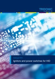
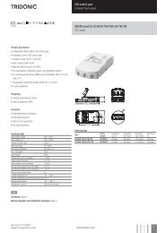
Product description<br />
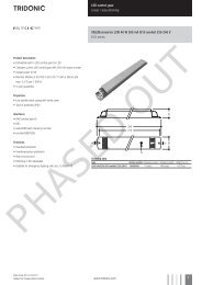
• Ready-for-use resistor to set output current value<br />
• Resistor is base isolated<br />
• Resistor power 0.25 W<br />
• Resistor value tolerance ± 1 %<br />
ACCES-<br />
SORIES<br />
CURRENT PLUG <strong>4x16</strong><br />
9<br />
5,5 3,5<br />
xxxx<br />
3,5<br />
6<br />
13,5<br />
Ordering data<br />
Type Article number Colour Marking<br />
Resistor<br />
value<br />
Packaging bag Weight per pc.<br />
CURRENT PLUG <strong>4x16</strong> 250mA 28000574 Pink 0250 43.2 kΩ 10 pc(s). 0.001 kg<br />
CURRENT PLUG <strong>4x16</strong> 300mA 28000359 Pink 0300 110.0 kΩ 10 pc(s). 0.001 kg<br />
CURRENT PLUG <strong>4x16</strong> 350mA 28000360 Pink 0350 309.0 kΩ 10 pc(s). 0.001 kg<br />
PHASED OUT<br />
Data sheet 06/14-LC054-4<br />
Subject to change without notice.<br />
www.tridonic.com 2
LED control gear<br />
Linear / area fixed output<br />
Standards<br />
EN 55015<br />
EN 61000-3-2<br />
EN 61000-3-3<br />
EN 61347-1<br />
EN 61347-2-13<br />
EN 61547<br />
EN 62384<br />
Overload protection / underload protection<br />
If the output voltage range is exceeded the LED control gear turns off the LED<br />
output and tries a restart every 6 seconds.<br />
Short-circuit behaviour<br />
In case of a short circuit on the secondary side (LED) the LED ouput is switched off.<br />
Every 6 seconds the LED control gear tries to restart.<br />
No-load operation<br />
The LED control gear will not be damaged in the no-load operation and will supply<br />
constantly 56 V.<br />
Operation on DC voltage<br />
The LED control gear is designed for operation with DC voltage and pulsed DC<br />
voltage.<br />
Light output level in DC operation: 100 %<br />
Harmonic distortion in the mains supply (at 230 V / 50 Hz and full load) in %<br />
THD 3. 5. 7. 9. 11.<br />
<strong>LCI</strong> <strong>4x16</strong>W <strong>200</strong>mA-<strong>400mA</strong> <strong>lp</strong> < 10 3.2 2.3 2.7 2.6 2.3<br />
Storage conditions<br />
Humidity: 5 % up to max. 85 %,<br />
not condensed<br />
(max. 56 days/year at 85 %)<br />
Storage temperature: -40 °C up to max. +80 °C<br />
The devices have to be within the specified temperature range (ta) before they<br />
can be operated.<br />
Maximum loading of automatic circuit breakers<br />
Automatic circuit breaker type C10 C13 C16 C20 B10 B13 B16 B20 Inrush current<br />
Installation Ø 1.5 mm 2 1.5 mm 2 2.5 mm 2 4 mm 2 1.5 mm 2 1.5 mm 2 2.5 mm 2 4 mm 2 I max<br />
Time<br />
<strong>LCI</strong> <strong>4x16</strong>W <strong>200</strong>mA-<strong>400mA</strong> <strong>lp</strong> 24 32 39 49 24 32 39 49 85 A 12 μs<br />
Wiring guidelines<br />
• The secondary cables should be run separately from the mains connections<br />
and mains cables to ensure good EMC conditions<br />
• The LED wiring should be kept as short as possible to ensure good EMC. The<br />
recommended secondary cable length is max. 2 m.<br />
• The converter does not have polarity reversal protection on the secondary<br />
side. LED modules that do not have polarity reversal protection may be<br />
damaged if polarity is reversed.<br />
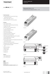
Installation instructions<br />
Wiring type and cross section<br />
Solid wire with a cross section of 0.5 – 1.5 mm². Strip 8 – 9 mm of insulation<br />
from the cables to ensure perfect operation of terminals.<br />
wire preparation:<br />
0.5 – 1.5 mm²<br />
8 – 9 mm<br />
PHASED OUT<br />
Release of the wiring<br />
Loosen wire through twisting and pulling or using a Ø 1 mm release tool.<br />
Data sheet 06/14-LC054-4<br />
Subject to change without notice.<br />
www.tridonic.com 3
LED control gear<br />
Linear / area fixed output<br />
Temperature range<br />
The LED control gear life duration is related to the ambient temperature ta.<br />
The relation of tc to ta temperature depends also on the luminaire design. If the<br />
measured tc temperature is approx. 5 K below tc max. or higher, ta temperature<br />
should be checked and eventually critical components (e.g. ELCAP) measured.<br />
Detailed information on request.<br />
The LED control gear is designed for an average life-time of 50,000 (at ta for<br />
≥ 50.000 h) hours under reference conditions and with a failure probability of<br />
less than 10 %. This corresponds to an average failure rate of 0.2 % for every<br />
1,000 hours of operation.<br />
LED’s have to be connected as shown at the circuit diagram to work properly.<br />
The minimum power load has to be connected. Otherwise the converter will switch<br />
off. Connect a resistor between I sel 1 und I sel 2 to reduce output current for all<br />
4 channels. Tabel below shows relationship between output current and resistor<br />
value. Resistor values come from the standardised E96 resistor value range.<br />
Min. resistor power is 0.1 W.<br />
Output current<br />
in mA<br />
Resistor<br />
in kΩ<br />
<strong>200</strong> 9.76<br />
220 21.00<br />
240 34.80<br />
250 43.20<br />
260 51.10<br />
280 76.80<br />
300 110.00<br />
320 158.00<br />
340 243.00<br />
350 309.00<br />
360 402.00<br />
380 909.00<br />
400 open<br />
Isolation and electric strength testing of luminaires<br />
Electronic devices can be damaged by high voltage. This has to be considered<br />
during the routine testing of the luminaires in production.<br />
According to IEC 60598-1 Annex Q (informative only!) or ENEC 303-Annex A, each<br />
luminaire should be submitted to an isolation test with 500 V DC for 1 second. This<br />
test voltage should be connected between the interconnected phase and neutral<br />
terminals and the earth terminal.<br />
The isolation resistance must be at least 2 MΩ.<br />
As an alternative, IEC 60598-1 Annex Q describes a test of the electrical strength<br />
with 1500 V AC (or 1.414 x 1500 V DC). To avoid damage to the electronic devices this<br />
test must not be conducted.<br />
Additional information<br />
Additional technical information at<br />
www.tridonic.com → Technical Data<br />
Guarantee conditions at<br />
www.tridonic.com → Services<br />
No warranty if device was opened.<br />
Expected life-time<br />
Type ta 40 °C 50 °C 60 °C<br />
<strong>LCI</strong> <strong>4x16</strong>W <strong>200</strong>mA-<strong>400mA</strong> <strong>lp</strong><br />
tc 67 °C 74 °C 83 °C<br />
Life-time 80,000 h 50,000 h 25,000 h<br />
x = not permitted<br />
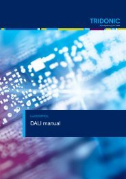
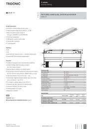
Circuit diagrams<br />
4 channel operation (max. output current 400 mA)<br />
I sel 1<br />
I sel 2<br />
LED 4<br />
LED 3<br />
LED 2<br />
LED 1<br />
Parallel circuit of 2 channels each (max. output current 800 mA)<br />
I sel 1<br />
I sel 2<br />
LED 4<br />
LED 3<br />
LED 2<br />
LED 1<br />
Parallel circuit of 3 channels (max. output current 1,<strong>200</strong> mA)<br />
I sel 1<br />
I sel 2<br />
LED 4<br />
LED 3<br />
LED 2<br />
LED 1<br />
+<br />
–<br />
+<br />
–<br />
+<br />
–<br />
+<br />
–<br />
+<br />
–<br />
+<br />
–<br />
+<br />
–<br />
+<br />
–<br />
+<br />
–<br />
+<br />
–<br />
+<br />
–<br />
+<br />
–<br />
PHASED OUT<br />
Parallel circuit of 4 channels (max. output current 1,600 mA)<br />
I sel 1<br />
I sel 2<br />
LED 4<br />
LED 3<br />
LED 2<br />
LED 1<br />
+<br />
–<br />
+<br />
–<br />
+<br />
–<br />
+<br />
–<br />
Data sheet 06/14-LC054-4<br />
Subject to change without notice.<br />
www.tridonic.com 4