
Create successful ePaper yourself
Turn your PDF publications into a flip-book with our unique Google optimized e-Paper software.
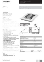
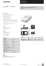
luxCONTROL lighting control system<br />
<strong>DALI</strong> actuator<br />
Product description<br />
• Digital leading-edge and trailing edge phase dimmers<br />
• Total connected load: 30 – <strong>300</strong> VA<br />
• <strong>one4all</strong> input: <strong>DALI</strong>, DSI and switchDIM input<br />
• 1 dimmed phase (output)<br />
• With automatic load detection<br />
• Surface-mounted casing<br />
• Status LED for indicating the operating status<br />
• Not suitable for operation with LED bulbs<br />
• 5-year guarantee<br />
Technical data<br />
Rated supply voltage<br />
220 – 240 V<br />
Mains frequency<br />
50 / 60 Hz<br />
Connected load<br />
30 – <strong>300</strong> VA<br />
Power loss<br />
0.75 W (1.8 W at full load)<br />
Ambient temperature ta 0 ... +50 °C<br />
Type of protection<br />
IP20<br />
È<br />
Standards, page 2<br />
Wiring diagrams and installation examples, page 2<br />
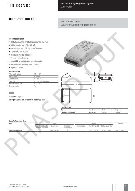
<strong>DALI</strong> <strong>PCD</strong> <strong>300</strong> <strong>one4all</strong><br />
Leading-edge/trailing-edge phase dimmer<br />
Ordering data<br />
Type Article number Packaging, carton Weight per pc.<br />
<strong>DALI</strong>-<strong>PCD</strong> <strong>300</strong> <strong>one4all</strong> 86458303 25 pc(s). 0.085 kg<br />
Specific technical data<br />
Type Inputs Outputs Terminals<br />
Input, <strong>DALI</strong>/DSI control Current draw Number of Dimmed phase Control range, DSI Control range, <strong>DALI</strong><br />
input and switchDIM<br />
<strong>DALI</strong> addresses<br />
<strong>DALI</strong>-<strong>PCD</strong> <strong>300</strong> <strong>one4all</strong> 1 2 mA from <strong>DALI</strong> 1 1 0; 1 – 100 % 0; 0.1 – 100 % 0.5 – 1.5 mm²<br />
PHASED OUT<br />
Data sheet 10/14-CO006-5<br />
Subject to change without notice.<br />
www.tridonic.com 1
luxCONTROL lighting control system<br />
<strong>DALI</strong> actuator<br />
Standards<br />
EN 61547<br />
EN 61347-2-11<br />
EN 60669-2-1<br />
EN 55015<br />
EN 55022<br />
EN 61000-3-2<br />
IEC 60929 (according to <strong>DALI</strong> standard V0)<br />
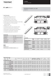
Phase dimmers with automatic load detection,<br />
leading-edge or trailing-edge. They are controlled<br />
via switches (switchDIM) or via a <strong>DALI</strong>/DSI signal.<br />
Total connected load: 30–<strong>300</strong> VA<br />
Area of application:<br />
Digital phase dimmers enable low-voltage tungstenhalogen<br />
lamps, in conjunction with electronic or<br />
magnetic transformers, and ohmic light sources<br />
(incandescent lamps) with a total output of 30 to<br />
<strong>300</strong> VA to be dimmed.<br />
Control is either via a <strong>DALI</strong>/DSI signal or directly<br />
connected switches (switchDIM).<br />
The digital phase dimmer is not compatible with LED<br />
retrofit lamps. LV halogen LED retrofit lamps that are<br />
operated by an electronic or magnetic transformer<br />
are also not compatible.<br />
Status-LED for the operating mode:<br />
Normal operation:<br />
LED off<br />
Overload:<br />
LED flashes slow (1/sec.)<br />
Short-circuit:<br />
LED flashes fast (5/sec.)<br />
Permanent short-circuit/overtemperature: LED on<br />
L<br />
N<br />
<strong>DALI</strong> <strong>PCD</strong> <strong>300</strong><br />
<strong>one4all</strong><br />
switchDIM:<br />
When a new unit is installed in an existing system or<br />
when the system is first put into operation the individual<br />
units are not synchronised. This means that<br />
some units will be at status on and some at status<br />
off. Pressing the switch briefly will change the<br />
status; units previously on will be switched off, but<br />
the rest will be switched on. By pressing the switch<br />
for longer than 10 seconds all the units will be<br />
synchronised to the same status. The synchronisation<br />
process is completed when all the lamps have<br />
assumed the same light value (50 %).<br />
The same synchronisation process may also be<br />
necessary during normal operation if an individual<br />
unit becomes unsynchronised because of an<br />
incorrect switching operation.<br />
30 – <strong>300</strong> VA<br />
30 – <strong>300</strong> VA<br />
LV tungstenhalogen<br />
switchDIM Incandescent lamps switchDIM switchDIM<br />
lamps<br />
<strong>DALI</strong>/DSI<br />
N<br />
N<br />
L<br />
DA/D1<br />
DA/D2<br />
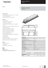
Mixed loads (capacitative, inductive and ohmic) may be used.<br />
Glow-wire test<br />
according to EN 60598-1 passed.<br />
Wiring type and cross section<br />
The wiring can be in stranded wires with ferrules or solid. For perfect function<br />
of the cage clamp terminals the strip length should be 4 – 5 mm for the input<br />
terminal.<br />
The max. torque at the clamping screw (M3) is 0.2 Nm.<br />
Side D2<br />
max. ∅ = 8,0 mm<br />
min. ∅ = 4,0 mm<br />
0,5 – 2,5<br />
4 – 5<br />
electronic transformator<br />
N<br />
N<br />
L<br />
DA/D1<br />
DA/D2<br />
<strong>DALI</strong> <strong>PCD</strong> <strong>300</strong><br />
<strong>one4all</strong><br />
switchDIM is a very simple tool for controlling ballasts<br />
with conventional momentary-action switches<br />
or motion sensors.<br />
To ensure correct operation a sinusoidal mains<br />
voltage with a frequency of 50 Hz or 60 Hz is<br />
required at the control input.<br />
Special attention must be paid to achieving clear<br />
zero crossings. Serious mains faults may impair the<br />
operation of switchDIM.<br />
<strong>DALI</strong> addressing:<br />
The <strong>DALI</strong> <strong>PCD</strong> <strong>300</strong> <strong>one4all</strong> also supports physical<br />
<strong>DALI</strong> addressing. Press the button between the<br />
terminals to assign the address.<br />
30 – <strong>300</strong> VA<br />
magnetic transformator<br />
N<br />
N<br />
L<br />
DA/D1<br />
DA/D2<br />
220 – 240 V AC<br />
50 / 60 Hz<br />
LV tungstenhalogen<br />
lamps<br />
<strong>DALI</strong> <strong>PCD</strong> <strong>300</strong><br />
<strong>one4all</strong><br />
To get a proper working strain relief it is recommended that the cable jacket<br />
diameter of the side D2 is 2 mm bigger than the diameter of the side D1. (This<br />
can vary if the used cable jacket material varies from side D2 to D1 in pinching<br />
property).<br />
PHASED OUT<br />
PRESS<br />
Side D1<br />
D1<br />
D2<br />
max. ∅ = 6,0 mm<br />
min. ∅ = 2,0 mm<br />
0,5 – 2,5<br />
4 – 5<br />
Data sheet 10/14-CO006-5<br />
Subject to change without notice.<br />
www.tridonic.com 2