TALEXXconverter LCAI 50 W 350 mA I010 one4all - Tridonic
TALEXXconverter LCAI 50 W 350 mA I010 one4all - Tridonic
TALEXXconverter LCAI 50 W 350 mA I010 one4all - Tridonic

You also want an ePaper? Increase the reach of your titles
YUMPU automatically turns print PDFs into web optimized ePapers that Google loves.
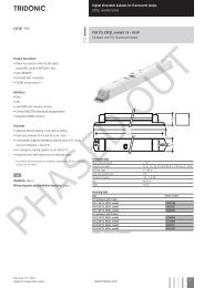
LED control gear<br />
Linear / area dimming<br />
Product description<br />
• Dimmable built-in LED control gear for LED<br />
• Constant current LED control gear with 3<strong>50</strong> <strong>mA</strong> output current<br />
• Output power <strong>50</strong> W<br />
• Nominal lifetime of <strong>50</strong>,000 h (at ta 55 °C with a failure rate<br />
max. 0.2 % per 1,000 h)<br />
• 5-year guarantee<br />
Properties<br />
• Low-profile metal casing with white cover<br />
• Type of protection IP20<br />
Interfaces<br />
• DALI (device type 6)<br />
• DSI<br />
• switchDIM (with memory function)<br />
• corridorFUNCTION<br />
Functions<br />
• Overload protection<br />
• Overtemperature protection<br />
• Short circuit proof<br />
• Dimming in DC adjustable<br />
• Suitable for emergency lighting units acc. to EN<strong>50</strong>172<br />
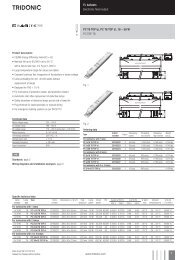
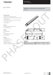
Uconverter <strong>LCAI</strong> <strong>50</strong> W 3<strong>50</strong> <strong>mA</strong> <strong>I010</strong> <strong>one4all</strong> 220-240 V<br />
ECO series<br />
Ordering data<br />
Type Article number Packaging carton Packaging pallet Weight per pc.<br />
<strong>LCAI</strong> 0<strong>50</strong>/03<strong>50</strong> <strong>I010</strong> <strong>one4all</strong> 220-240 V 86459431 10 pc(s). 960 pc(s). 0.215 kg<br />
PHASED OUT<br />
Data sheet 02/14-LC046-3<br />
Subject to change without notice.<br />
www.tridonic.com 1
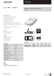
LED control gear<br />
Linear / area dimming<br />
Technical data<br />
Rated supply voltage<br />
220 – 240 V<br />
AC Voltage range<br />
198 – 264 V<br />
DC Voltage range<br />
170 – 280 V<br />
Mains frequency<br />
Typ. rated current (at 230 V / <strong>50</strong> Hz / full load) 1<br />
Mains current (at 220 V / 0 Hz / full load) 2<br />
Leakage current (PE)<br />
Max. input power<br />
0 / <strong>50</strong> / 60 Hz<br />
0.2 A<br />
0.05 A<br />
0.25 <strong>mA</strong><br />
59 W<br />
Typ. efficiency (at 230 V / <strong>50</strong> Hz / full load) 1 90 %<br />
Typ. λ (at 230 V / <strong>50</strong> Hz / full load) 1 0.95<br />
Typ. power input on standby<br />
1 W<br />
Dimming range 3 – 100 %<br />
PWM frequency<br />
400 Hz<br />
Typical ripple current at full load ± 15 %<br />
Max. non-repetitive output peak current<br />
Switch-on time (DC mode)<br />
620 <strong>mA</strong><br />
0.4 s<br />
Switch-on time (at 230 V / <strong>50</strong> Hz / full load / acc. to 0.6 s<br />
the DALI standard) 1<br />
Switchover time (AC/DC)<br />
Turn off time (at 230 V / <strong>50</strong> Hz / full load)<br />
Hold on time at power failure (output)<br />
0.2 s<br />
0.1 s<br />
20 ms<br />
ta operating (at life time <strong>50</strong>,000 h) -20 ... +55 °C<br />
Max. casing temperature tc 75 °C<br />
Dimensions LxWxH<br />
Hole spacing D<br />
Specific technical data<br />
280 x 30 x 21 mm<br />
270 mm<br />
Type Output current 1 Output current tolerance 1 Output voltage range Max. output voltage3 Typ. output power<br />
<strong>LCAI</strong> 0<strong>50</strong>/03<strong>50</strong> <strong>I010</strong> <strong>one4all</strong> 220-240 V 3<strong>50</strong> <strong>mA</strong> ± 5 % 60 – 142 V 420 V <strong>50</strong> W<br />
1 Valid at 100 % dimming level<br />
2<br />
Valid at 15 % dimming level<br />
3<br />
In no-load operation<br />
PHASED OUT<br />
Data sheet 02/14-LC046-3<br />
Subject to change without notice.<br />
www.tridonic.com 2
LED control gear<br />
Linear / area dimming<br />
Standards<br />
EN 5<strong>50</strong>15<br />
EN 61000-3-2<br />
EN 61000-3-3<br />
EN 61347-1<br />
EN 61347-2-13<br />
EN 61547<br />
EN 62384<br />
IEC 62386-101<br />
IEC 62386-102<br />
IEC 62386-207<br />
According to the EN <strong>50</strong>172 suitable for central battery systems<br />
According to the EN 60598 suitable for emergency lighting installations<br />
Overload protection / underload protection<br />
If the output voltage range is exceeded the LED control gear turns off the LED<br />
output and tries a restart every 6 seconds. The overload protection is deactivated<br />
in emergency operation.<br />
Overtemperature protection<br />
The LED control gear is protected against temporary thermal overheating. If the<br />
temperature limit is exceeded the output current of the LED is reduced. The temperature<br />
protection is activated between 8 and 12 °C above tc max (see page 1).<br />
This function is deactivated in emergency operation.<br />
Short-circuit behaviour<br />
In case of a short circuit on the secondary side (LED) the LED ouput is switched off.<br />
Every 6 seconds the LED control gear tries to restart.<br />
No-load operation<br />
The LED control gear is not damaged in the no-load operation. Every 6 seconds<br />
the LED control gear tries to restart. The max. output voltage (see page 1) can be<br />
obtained for a short time (<strong>50</strong> ms) during no-load operation.<br />
Harmonic distortion in the mains supply (at 230 V / <strong>50</strong> Hz and full load) in %<br />
THD 3. 5. 7. 9. 11.<br />
<strong>LCAI</strong> 0<strong>50</strong>/03<strong>50</strong> <strong>I010</strong> <strong>one4all</strong> 220-240 V 10 8 1.5 2.5 3 1.5<br />
Expected lifetime<br />
Type ta = <strong>50</strong> °C ta = 55 °C<br />
<strong>LCAI</strong> 0<strong>50</strong>/03<strong>50</strong> <strong>I010</strong> <strong>one4all</strong> 220-240 V<br />
tc 70 °C 75 °C<br />
Lifetime 75,000 h <strong>50</strong>,000 h<br />
Storage conditions<br />
Humidity: 5 % up to max. 85 %,<br />
not condensed<br />
(max. 56 days/year at 85 %)<br />
Storage temperature: -40 °C up to max. +80 °C<br />
The devices have to be within the specified temperature range (ta) before they<br />
can be operated.<br />
Maximum loading of automatic circuit breakers<br />
Automatic circuit breaker type C10 C13 C16 C20 B10 B13 B16 B20 Inrush current<br />
Installation Ø 1.5 mm 2 1.5 mm 2 2.5 mm 2 4 mm 2 1.5 mm 2 1.5 mm 2 2.5 mm 2 4 mm 2 I max<br />
Duration<br />
<strong>LCAI</strong> 0<strong>50</strong>/03<strong>50</strong> <strong>I010</strong> <strong>one4all</strong> 220-240 V 16 20 26 32 8 10 14 17 31 A 220 μs<br />
PHASED OUT<br />
Data sheet 02/14-LC046-3<br />
Subject to change without notice.<br />
www.tridonic.com 3
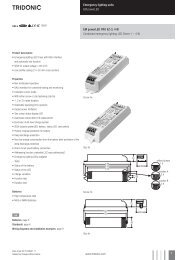
LED control gear<br />
Linear / area dimming<br />
Dimming<br />
Dimming range 3 % to 100 %<br />
Digital control with:<br />
• DSI signal: 8 bit Manchester Code<br />
Speed 3 % to 100 % in 1.4 s<br />
• DALI signal: 16 bit Manchester Code<br />
Speed 3 % to 100 % in 0.1 s<br />
Programmable parameter:<br />
Minimum dimming level<br />
Maximum dimming level<br />
Default minimum = 3 %<br />
Programmable range 3 % ≤ MIN ≤ 100 %<br />
Default maximum = 100 %<br />
Programmable range 100 % ≥ MAX ≥ 3 %<br />
Dimming curve is adapted to the eye sensitiveness.<br />
Control input (DA/D1, DA/D2)<br />
Digital DALI signal or switchDIM can be wired on the same terminals<br />
(DA/D1 and DA/D2).<br />
Digital signal DALI/DSI<br />
The control input is non-polar and protected against accidental connection with<br />
a mains voltage up to 264 V. The control signal is not SELV. Control cable has to<br />
be installed in accordance to the requirements of low voltage installations.<br />
Different functions depending on each module.<br />
switchDIM<br />
Integrated switchDIM function allows a direct connection of a push to make<br />
switch for dimming and switching.<br />
Brief push (< 0.6 s) switches LED control gear ON and OFF. The LED control<br />
gears switch-ON at light level set at switch-OFF.<br />
When the push to make switch is held, LED modules are dimmed. After repush<br />
the LED modules are dimmed in the opposite direction.<br />
In installations with LED control gears with different dimming levels or opposite<br />
dimming directions (e.g. after a system extension), all LED control gears can be<br />
synchronized to <strong>50</strong> % dimming level by a 10 s push.<br />
Use of push to make switch with indicator lamp is not permitted.<br />
Dimming characteristics<br />
Digital dimming value<br />
255<br />
225<br />
200<br />
DALI<br />
175<br />
DSI<br />
1<strong>50</strong><br />
125<br />
100<br />
75<br />
<strong>50</strong><br />
25<br />
0<br />
0 10 20 30 40 <strong>50</strong> 60 70 80 90 100<br />
Relative lighting level %<br />
Dimming characteristics as seen by the human eye<br />
corridorFUNCTION<br />
The corridorFUNCTION can be programmed in two different ways.<br />
To program the corridorFUNCTION by means of software a DALI-USB interface is<br />
needed in combination with a DALI PS. The software can be the<br />
masterCONFIGURATOR.<br />
To activate the corridorFUNCTION without using software a voltage of 230 V simply<br />
has to be applied for five minutes at the switchDIM connection.<br />
The unit will then switch automatically to the corridorFUNCTION.<br />
Note:<br />
If the corridorFUNCTION is wrongly activated in a switchDIM system (for example a<br />
switch is used instead of pushbutton), there is the option of installing a pushbutton<br />
and deactivating the corridorFUNCTION mode by five short pushes of the button<br />
within three seconds.<br />
switchDIM and corridorFUNCTION are very simple tools for controlling ballasts<br />
with conventional momentary-action switches or motion sensors.<br />
To ensure correct operation a sinusoidal mains voltage with a frequency of <strong>50</strong> or<br />
60 Hz is required at the control input.<br />
Special attention must be paid to achieving clear zero crossings. Serious mains<br />
faults may impair the operation of switchDIM and corridorFUNCTION.<br />
Light output level in DC operation<br />
Programmable from 3 % to 100 %<br />
Programming by extended DSI or DALI signal (16 bit).<br />
Default value is 15 %<br />
In DC operation dimming mode can be activated.<br />
Programming<br />
With appropriate software and a USB interface different functions can be activated<br />
and various parameters can be configured in the uconverter <strong>LCAI</strong> 0<strong>50</strong>/3<strong>50</strong><br />
<strong>I010</strong> <strong>one4all</strong>. All that is needed is a DALI-USB and the software<br />
(masterCONFIGURATOR).<br />
PHASED OUT<br />
masterCONFIGURATOR<br />
For programming the corridorFUNCTION, device configuration (fade time,<br />
ePowerOnLevel, etc.) DC level, compatibility settings, and startup date and for<br />
resetting.<br />
Data sheet 02/14-LC046-3<br />
Subject to change without notice.<br />
www.tridonic.com 4
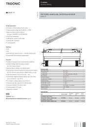
LED control gear<br />
Linear / area dimming<br />
Wiring guidelines<br />
• The secondary cables should be run separately<br />
from the mains connections and mains cables to<br />
ensure good EMC conditions<br />
• The LED wiring should be kept as short as<br />
possible to ensure good EMC. The max. secondary<br />
cable length must not exceed 2 m. Cable lengths<br />
bigger than 2 m may lead to a malfunction of the<br />
LED control gear.<br />
• Secondary switchting is not permitted.<br />
• The LED control gear does not have polarity reversal<br />
protection on the secondary side.<br />
LED modules that do not have polarity reversal<br />
protection may be damaged if polarity is reversed.<br />
Circuit diagrams<br />
* * control signal<br />
* * control signal<br />
1<br />
3<br />
4<br />
6<br />
7<br />
DA<br />
DA<br />
* * digital DSI/DALI signal<br />
1<br />
3<br />
4<br />
6<br />
7<br />
DA<br />
DA<br />
* * digital DSI/DALI signal<br />
+<br />
–<br />
+<br />
–<br />
+<br />
–<br />
Wiring type and cross section<br />
The wiring can be in stranded wires with ferrules or<br />
solid from 0.5 – 1.5 mm². For perfect function of<br />
the push-wire terminals (WAGO 2<strong>50</strong>) the strip length<br />
should be 7.5 – 8.5 mm.<br />
wire preparation:<br />
0.5 – 1.5 mm²<br />
7.5 – 8.5 mm<br />
LED control gear is not SELV (output voltage up to 420 V).<br />
LED’s have to be connected as shown above to work properly. It is possible to connect a different number of LED’s on two circuits (like on<br />
top picture). The minimum power load has to be connected. Otherwise the LED control gear will switch off.<br />
Operation on DC voltage<br />
The LED control gear is designed for operation with DC<br />
voltage and pulsed DC voltage.<br />
<br />
N<br />
* *<br />
L<br />
N<br />
* *<br />
L<br />
1<br />
3<br />
4<br />
6<br />
7<br />
* * switchDIM<br />
1<br />
3<br />
4<br />
6<br />
7<br />
DA<br />
DA<br />
DA<br />
DA<br />
* * switchDIM<br />
Release of the wiring<br />
Press down the “push button” and remove<br />
the cable from front.<br />
<br />
<br />
PHASED OUT<br />
+<br />
–<br />
+<br />
–<br />
+<br />
–<br />
<br />
Data sheet 02/14-LC046-3<br />
Subject to change without notice.<br />
www.tridonic.com 5