REMOTE CONTROL RC10.pdf
REMOTE CONTROL RC10.pdf
REMOTE CONTROL RC10.pdf

You also want an ePaper? Increase the reach of your titles
YUMPU automatically turns print PDFs into web optimized ePapers that Google loves.
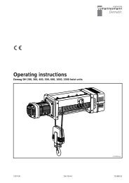
Operating Instructions<br />
RC-10 Radio Remote Control<br />
1098 EN<br />
214 376 44<br />
720 IS 975 1
Manufacturer<br />
Mannesmann Dematic AG<br />
P.O. Box 67, D-58286 Wetter<br />
Tel: (+ 2335) 92-0, Fax: (+ 2335) 927676<br />
Internet http://www.dematic.com<br />
Contents<br />
1 Principle 3<br />
2 Safety Instructions 4<br />
2.1 Symbols 4<br />
2.2 Appropriate use 4<br />
2.3 Prohibited Practices 4<br />
2.4 General safety information 5<br />
2.5 Safety during assembly and dismantling 6<br />
2.6 Safety instructions following installation 6<br />
2.7 Safety instructions during operation. 6<br />
3 Hand Transmitter RC-H 10 9<br />
3.1 Electronic Key 9<br />
3.2 Stand-By mode 10<br />
3.3 Battery condition indicator 10<br />
3.4 Test radio connection transmitter/receiver 11<br />
3.5 Stop mode 11<br />
3.6 Frequency change-over 12<br />
3.6.1 Frequency change manual operation 12<br />
4 Charging Equipment 12<br />
5 RC-E 10 Receiver 13<br />
5.1 Assembly and connection of the receiver 13<br />
5.2 Description of receiver LEDs 13<br />
5.3 Address adjustment 14<br />
5.3.1 Changing address code in the receiver 15<br />
5.4 Contact arrangements 16<br />
5.5 Wiring diagram for the receiver 17<br />
6 Pre-commission Measures 18<br />
6.1 Receiver function check 18<br />
7. Symbols on Transmitter and Lifting Unit. 18<br />
7.1 Manual transmitter 18<br />
7.2 Identification labels for lifting equipment 19<br />
8 Accessories 20<br />
9 Technical Data 21<br />
10 Basic Wiring Diagram 22<br />
11 Dimensions 23<br />
12 International Postal Registration 24<br />
EC - Declaration of Conformity. 25<br />
2
1 Principle<br />
With the RC-10 remote control unit tracked vehicles, travelling hoists, cranes, shuttle<br />
cars and other machines can be controlled without the need for direct wiring.<br />
Thus, in the above mentioned machines conventional control equipment can be<br />
dispensed with. The operator can position himself anywhere. He can operate loads<br />
and move equipment from a safe distance.<br />
The equipment to be controlled must be fitted with low voltage contactors.<br />
The RC-10 remote control unit is specifically designed for individual operation; this<br />
means that there is always a clear relationship between a particular transmitter and<br />
a particular receiver. Should there be a requirement for multi-sender operation<br />
(where several transmitters operate with one receiver) we would recommend the IR<br />
infra-red control system.<br />
3
2 Safety Instructions<br />
2.1 Symbols The following symbols and instructions warn against possible personal injuries or<br />
damage to property and are intended to assist youb in your work.<br />
Safety at work symbol<br />
This symbol appears in the operating instructions next to all instructions relating to<br />
safety at work wherever a potential danger to life and limb exists.<br />
Follow these instructions at all times and be particularly careful and cautious.<br />
Pass on safety instructions to all persons entrusted with working on the equipment<br />
including track and power supply.<br />
In addition to the safety instructions, observe all general safety regulations and factory<br />
accident prevention regulations at all times.<br />
Warning against electrical hazards<br />
Contact with live parts can result in immediate death. Protective covers (e.g. covers<br />
and enclosures of electrical equipment) marked with this sign may only be opened<br />
by qualified electricians. Before opening, all relevant operating, control, feed or other<br />
voltages must be disconnected.<br />
Operational hazard for the installation<br />
This symbol in the operating instructions indicates all warnings which, if not<br />
complied with, may result in malfunctions or damage to the equipment.<br />
2.2 Appropriate use<br />
Equipment may only be operated when in perfect working order by trained<br />
personnel in accordance with the relevant safety and accident prevention<br />
regulations. This also includes compliance with operating and maintenance<br />
conditions specified in the operating instructions. The product is to be operated at<br />
the rated voltage which appears on the manufacture’s rating plate.<br />
The relevant isolating switch must be switched off and secured when performing<br />
maintenance/repair work.<br />
During operation or when the main switch is not switched off, electrical components<br />
inside enclosures, motors, switchgear cabinets, load handling attachments, terminal<br />
boxes etc., carry dangerous voltages. This voltage may cause fatal injuries.<br />
Serious personal injury or damage to property may occur in the event of:<br />
• unauthorised removal of covers.<br />
• inappropriate use of the equipment.<br />
• incorrect operation.<br />
• insufficient maintenance.<br />
• working on components without isolating power.<br />
2.3 Prohibited Practices<br />
Certain work and actions are not permitted with this product since they can, in certain<br />
circumstances, be a danger to life and limb, and can cause permanent damage<br />
to the product. For example:<br />
• Tampering with electrical equipment.<br />
• Mains connection to voltages and frequencies other than those stated on the<br />
specification block.<br />
• Non observance of the accompanying instructions covering installation.<br />
• Non compliance with the maximum permitted working temperature.<br />
4
2.4 General safety<br />
information<br />
Persons under the influence of drugs, alcohol or medicines which affect reactions<br />
must not install, operate, put into service, maintain, repair or disassamble the<br />
equipment. Major reconstruction and changes to the equipment shall only be<br />
undertaken in accordance with the technical safety requirements. Work on electrical<br />
equipment may only be carried out by qualified electricians in accordance with<br />
electrical regulations. In the event of malfunctions, hoist unit operation must be<br />
stopped, the equipment switched off and the relevant main switches locked<br />
immediately.<br />
Defects must be rectified immediately!<br />
Accident prevention regulations appropriate to the relevant country and the general<br />
safety regulations must be strictly observed during the operation of our product.<br />
Important information and instructions are marked by corrsponding symbols. Follow<br />
these instructions and/or safety regulations in order to avoid accidents and damage.<br />
The operating instructions must be kept available at the place where the equipment<br />
is in use at all times. They include significant aspects and appropriate excertpts<br />
from relevant guidelines, standards and regulations. The owner must instruct his<br />
personnel appropriately.<br />
Any failure to comply withthe safety instructions stated in these operating<br />
instructions can result in death or personal injury.<br />
Observe general statutory and other obligatory regulations relating to accident<br />
prevention and environmental protection and basic health and safety requirements<br />
in addition to those included in these operating instructions. Such requirements may<br />
also relate, for example, to the handling of hazardous materials or the provision/<br />
wearing of personal protection equipment. Comply with these regulations and<br />
general prevention regulations relevant for the place at which the equipment is used<br />
and follow the instructions therein when working with the equipment. The<br />
equipment may stuill constitute a danger to life and limb if it is not installed.<br />
operated, maintained or used appropriately by personnel which have not been<br />
trained or specially instructed. The operating instructions must, if required, be<br />
supplemented by the owner with instructions and information (e.g. factory<br />
regulations) relating to organization of work, working procedures, operating<br />
personnel, etc. Supervising and reporting obligations as well as special operating<br />
conditions must also be taken into consideration.<br />
Personnel assigned to working with the equipment must have read and understood<br />
the operating instructions and, in particular, the chapter on safety information.<br />
All activities relating to the equipment which are not described in these operating<br />
instructions may only be carried out by specialist trained personnel specifically<br />
trained for the particular equipment.<br />
The owner must ensure that personnel work in a safety and hazard-conscious<br />
manner in compliance with the operating instructions.<br />
The owner must ensure that the equipment is only operated when in proper working<br />
order and that all relevant safety requirements and regulations are complied with.<br />
Equipment must be taken out of service immediately if functional defects or<br />
irregularities are detected. In the event of a stoppage (e.g. if defects regarding safe<br />
and reliable operation are detected, in emergency situations, in the event of<br />
operating malfunctions, for repairs and maintenance purposes, if damage is<br />
detected or after finishing work), the operator/experienced technician must carry out<br />
all prescribed safety measures. Personal protective clothing must be worn as<br />
necessary or as required by regulations. Personnel must not wear loose clothing,<br />
jewellery including rings or long hair loose. Injury may occur, for example, by being<br />
caught or drawn into the mechanism.<br />
All safety and hazard information and recommendations on the equipment, e.g. at<br />
access points and mains connection switches must be maintained in complete and<br />
legible condition.<br />
Modifications, additions to and conversions of the equipment which may impair<br />
safety in any way must not be carried out without the written consent of<br />
Mannesmann Dematic AG.<br />
Safety devices must not be rendered inoperative.<br />
Only genuine Mannesmann Dematic AG spare parts and accessories may be used.<br />
Observe prescribed deadlines or those specified in the operating instructions for<br />
routine checks/inspections.<br />
5
2.5 Safety instructions for<br />
installation and<br />
disassembly<br />
• Installation and disassembly work may only be performed by experienced technicians.<br />
• Installation and disassembly work must be coordinated by the person carrying<br />
out the work and the owner within the scope of their responsibility.<br />
• The working and danger zone must be made safe.<br />
• The installation must be isolated in accordance with the relevant electrical regulations.<br />
• Customer-specific regulations must be observed.<br />
• Only appropriate, tested and calibrated tools and equipment may be used.<br />
2.6 Safety instructions<br />
when first putting the<br />
equipment into<br />
service after<br />
completing installation<br />
• The working area or danger zone must be made safe.<br />
• First check that the voltage and frequency specified on the data plates match the<br />
owner’s mains power supply.<br />
• On commissioning it may be necessary to defeat safety devices for the purposes<br />
of adjustment and operational testing.<br />
• During commissioning it may be necessary to carry out work in dangerous positions,<br />
therefore care must be taken that only trained personnel are employed in<br />
this work.<br />
2.7 Safety instructions<br />
for operation<br />
All instructions and measures described in the operating instructions with regard to<br />
safe operation and items concerning general safety and accident prevention which<br />
have to be observed before, during and after putting into service must be strictly<br />
complied with. Any failure to comply can lead to accidents resulting in fatalities.<br />
Equipment must be taken out of service immediately or not put into operation if any<br />
defects relating to operating safety and reliability are detected.<br />
Safety devices must not be rendered inoperative or modified in contradiction to their<br />
intended use.<br />
Only operate equipment when all protective devices and safety-relevant equipment,<br />
e.g. movable protective devices and emergency-stop devices, are fitted and fully<br />
functioning.<br />
Power shall be switched off immediately where there is evidence of damage to<br />
electrical equipment and cables and insulation.<br />
Ensure that nobody is endangered by operation of the equipment before switching<br />
on/putting the equipment into operation!<br />
If the operator notices persons who may be exposed to a risk to health or personal<br />
safety by operation of the equipment, he must suspend operation immediately and<br />
may not resume operation again until the persons are outside the danger zone.<br />
Before putting the equipment into operation, the operator must be satisfied that the<br />
installation is in safe and correct operating condition.<br />
Work on equipment may only be carried out when instructions to this effect have<br />
been issued, when operation and function of the equipment have been explained<br />
and when the working and danger zone has been made safe.<br />
Cooling devices, such as ventilation openings, may not be rendered permanently<br />
inoperative (e.g. covered or closed).<br />
Special local conditions or special applications can lead to situations which were not<br />
known when this chapter was written. In such cases, special safety measures must<br />
be implemented by the owner.<br />
6
Parts List for RC-10 Order No.<br />
Radio control RC-10 772 970 44<br />
Complete unit<br />
1 RC-E 10 receivers 42-230 V 50/60 Hz 772 953 44<br />
1 RC-H 10 handset 772 951 44<br />
2 Batteries 6V 895 656 44<br />
1 Charging unit (accum.) 240 V 50/60 Hz 895 715 44<br />
1 Operating instructions Remote control RC-10 214 375 44<br />
1 Coding label for hand set RC-H 10 772 967 44<br />
1 Coding label black and white 895 639 44<br />
1 Coding label 7 segments (yellow) 895 640 44<br />
Instruction:<br />
Where the radio remote control unit RC-10 is installed in cranes the operators<br />
must read the regulations and instructions VBG 9.<br />
All equipment is designed for use in the industrial areas.<br />
The radio control RC-10 is manufactured according to regulations and rules for the<br />
VBG 9 for cranes, the ZH 1/547 guide lines for the remote control of cranes and<br />
pr EN 12077-1.<br />
All equipment is checked according to EMV (electro-magnetic compatibility) guide<br />
lines and fulfils the requirements of standards relating to interference and suppression<br />
for use in industry.<br />
So that the EMV conditions during the installation of complete units can be fulfilled,<br />
the following points must be observed:<br />
• EMV correct assembly of components<br />
• Use of correct wiring, if required use screened cables.<br />
• Adherence to the minimum gaps in covering of cables with differing voltage potential.<br />
7
Stop / 2 sec shut-down<br />
The receivers are fitted with additional relays which open after 2 seconds during a<br />
break in command and are re-set with the next command.. According to each<br />
individual requirement this relay contact can be fitted in series with the stop button<br />
or can be included separately in the control (see fig. 20 on p.22).<br />
If the stop command is initiated by pressing the stop button on the hand transmitter,<br />
this command will be stored in the transmitter as well as the receiver and the<br />
equipment will be entirely switched off via the main protection (see chapter 3.5 Stop<br />
Mode).<br />
The stop command is erased by insertion of the electronic key (see chapter 3.1<br />
Electronic Key).<br />
Emergency Stop<br />
Every lifting device must provide the facility to interrupt the electricity supply to any<br />
moving parts under load.<br />
This task is undertaken by cableless remote control of the mains switch. This must<br />
occur immediately and shall be designed as a circuit breaker.<br />
Should it be necessary, for reasons of quick operation or safety, to have more than<br />
one emergency stop point, the system must be designed as shown in fig 1. This<br />
design contains a circuit breaker with a low voltage switch, main fuses as well as<br />
power transformer with primary and secondary fuses. In addition and according to<br />
local conditions emergency stop buttons S1 -Sn are required.<br />
The equipment described above is standard and can be delivered under the part<br />
number given in chapter 8 .<br />
Q0<br />
L1<br />
L2<br />
L3<br />
PE<br />
F011<br />
F012<br />
F012<br />
Q011<br />
PE<br />
T013<br />
PE<br />
F014<br />
C1 <<br />
S1 S2 Sn<br />
Fig 1<br />
41405144.eps<br />
8
3 Hand transmitter RC-H 10<br />
3.1 Electronic Key<br />
As a protection against unauthorised use the hand transmitter is equipped with an<br />
electronic key as prescribed in pr EN 12077-1. Only after punching in a certain key<br />
sequence will the hand transmitter be operational.<br />
Three red LED’s (light emitting diodes) light up First LED changes colour from red to green<br />
RED<br />
RED<br />
RED<br />
GREEN<br />
RED<br />
RED<br />
I/O<br />
I/O<br />
2<br />
LIFT<br />
1. Stage<br />
press<br />
1<br />
STOP<br />
1. Stage<br />
keep pressed<br />
Keep pressed<br />
STOP Mode<br />
The transmitter sends an active STOP signal<br />
Fig 2<br />
41922710/01.eps<br />
A buzzer will sound if an incorrect key sequence is<br />
entered. If no entry is made after 2 seconds the<br />
transmitter will switch to the STOP mode.<br />
41922711/02.eps<br />
Two LEDs llight up green.<br />
Three LEDs light up green, the transmitter is ready<br />
for further use.<br />
GREEN<br />
GREEN<br />
RED<br />
GREEN<br />
GREEN<br />
RED<br />
GREEN<br />
GREEN<br />
GREEN<br />
I/O<br />
I/O<br />
I/O<br />
3<br />
LOWER<br />
1. stage<br />
press<br />
Keep pressed<br />
4<br />
STOP<br />
2. Stage keep<br />
pressed<br />
5 STOP<br />
Release<br />
button<br />
immediately<br />
Fig 3<br />
A buzzer will sound if an incorrect key sequence is<br />
entered. If no entry is made after 2 seconds the<br />
transmitter will switch to the STOP mode.<br />
As soon as all 3 LEDs show GREEN the STOP<br />
button must be released immediately<br />
Otherwise the transmitter will revert to the STOP<br />
mode.<br />
41922712/03.eps 41922710/03.eps 41922715/05.eps<br />
9
3.2 Stand-By Mode If after being put in the operation position the transmitter is not activated with the<br />
electronic key then the transmitter automatically switches into the Stand-Bye mode<br />
in order to maintain the battery. This Stand-Bye mode is indicated by the green<br />
flashing light on the right hand side of the unit.<br />
3.3 Battery condition<br />
indicator<br />
FLASH-<br />
ING<br />
GREEN<br />
I/O<br />
Fig 4<br />
41922744/06.eps<br />
The right hand red light illuminates as a warning signal for “battery low”. Following<br />
this the battery has sufficient capacity for approximately a further 10 minutes work.<br />
On activating the buttons a buzzer in the hand transmitter will sound.<br />
RED<br />
I/O<br />
LED RED<br />
Battery is low!<br />
Fig 5<br />
41922744/07.eps<br />
10
3.4 Test radio connection<br />
transmitter to receiver<br />
FLASH-<br />
ING<br />
GREEN<br />
I/O<br />
In STAND-BY mode radio contact with the<br />
receiver can be checked by pressing the<br />
button marked HORN.·Should the horn not<br />
sound then a new frequency must be selected<br />
(see section 3.6)<br />
Fig 6<br />
41922714/06.eps<br />
Instruction<br />
The RC-10 remote control unit works with a variable frequency. With the aid<br />
of a frequency switch the user can select a new frequency which is not<br />
covered by other transmitters. See chapter 3.6 Frequency change-over.<br />
3.5 Stop mode<br />
OFF<br />
OFF<br />
OFF<br />
FLASH-<br />
ING<br />
GREEN<br />
RED<br />
RED<br />
RED<br />
OFF<br />
I/O<br />
I/O<br />
STOP-Mode<br />
By pressing the STOP button in the<br />
STAND-BY mode an active stop signal is<br />
transmitted; the transmitter subsequently<br />
reverts to the STOP mode and must be<br />
released by the electronic key before it<br />
can be used again (see chapter 3.1).<br />
Fig 7<br />
41922710/06/08.eps<br />
11
3.6 Frequency<br />
change-over<br />
3.6.1 Frequency change<br />
manual operation<br />
As a special feature the RC-10 remote control unit has the facility for variable frequency:<br />
After switching on the RC-10 remote control unit or by pressing the buttons on the<br />
transmitter the receiver seeks out the corresponding transmitter within the available<br />
frequency range.<br />
Advantage:<br />
In built up areas around the receiver there is an increasing use of frequencies.<br />
A unit with variable frequency offers the best conditions for interference free<br />
transmission and reception.<br />
FLASH-<br />
ING<br />
GREEN<br />
I/O<br />
By simultaneously pressing the buttons HORN<br />
and F2 the frequency change-over can be<br />
activated.<br />
On releasing the button F2 a horn will sound,<br />
contact between transmitter and receiver on a<br />
free channel, not interfered with by other transmitters,<br />
will be re-established.<br />
The transmitter shall be once again in the<br />
STAND-BY mode. Should the horn not sound<br />
then the procedure should be repeated. The<br />
newly adjusted frequency will be permanently<br />
stored in the hand transmitter - even if a change<br />
of battery is necessary.<br />
Fig 8<br />
41922713/06.eps<br />
4 Charging equipment<br />
This unit serves to charge up batteries suitable for RC-10 manual transmitters: the<br />
built in green LED illuminates during he course of the charging operation.<br />
For the long life of the NiMH-Z cells used in the battery, it is advantageous not to<br />
place them in the charging unit after short term use, but only after they have been<br />
discharged.<br />
LED<br />
green<br />
Note:<br />
The capacity of a single battery is sufficient for approx. 8 hours work<br />
(50% working; 50% stand-bye). For use in two or three shift working systems<br />
a greater number of batteries is required and where necessary additional<br />
charging equipment (see chapter 8 -Accessories).<br />
12<br />
Fig 9<br />
41410244.eps
5 RC-E 10 receiver<br />
5.1 Assembly and<br />
connection of the<br />
receiver<br />
Securing the receiver<br />
• Screw the adapter plate (see fig 21 on p.23) to the selected surface (switch unit<br />
or wall etc).<br />
• Mount the receiver on the mounting plate and secure.<br />
Connect the receiver to the control equipment by means of multi connector block.<br />
Power will then be available to the receiver.<br />
Fig 10<br />
42039244.eps<br />
41922644.eps<br />
• Observe working voltage of the receiver<br />
• Always mount the receiver in the vertical position<br />
• Do not position the receiver in switch housings or recesses<br />
5.2 Description of<br />
receiver LEDs<br />
LEDs<br />
3.820.XXXX<br />
1<br />
2<br />
3<br />
4<br />
ZULASSUNG - TYPE APPROVAL - AGREMENT - HOMOLOGATION<br />
A GZ 421 751-ZB/95 GB 10668<br />
B RTT/TI/X069<br />
H MU-40.039-083/96<br />
BRDG120913F/G129014H<br />
I DCSR/2/4/144/03/320087/0037571<br />
/G120912F/A109460D N N096000433-R/N095000545-R<br />
CH BAKOM 95.0720.K.P<br />
N095000546-R<br />
BAKOM 95.0048.K.P NL NL95080771/NL95030271<br />
CZ 45251983<br />
PL 1027/96<br />
DK ALR 9654/ALR 9563 S Ue960012/Un940069<br />
FR 940032 PPL 0<br />
SF Fl95080136/Fl96080077<br />
PNN-BUS-3<br />
SERIAL NO. :<br />
HF MODULE :<br />
FREQUENCY :<br />
Mannesmann Dematic AG<br />
Typ RC-E 10 Id.-No. 77295344<br />
42-240V 50/60Hz 9VA<br />
0397<br />
999 765 4321<br />
E-EM43A0<br />
BAND F<br />
LEDs on the receiver indicate the operational condition<br />
and incorrect messages<br />
LED1<br />
LED2<br />
LED3<br />
LED4<br />
If this LED flashes when transmitter is<br />
switched on then there is interference on<br />
the radio channel<br />
Trip frequency change-over.<br />
Regular flashing:<br />
Data from the transmitter has been received<br />
Irregular Flashing:<br />
Possible interference on the radio channel<br />
Trip frequency change-over.<br />
HF signal evident<br />
When transmitter is switched on LED lights<br />
up permanently.<br />
POWER ON:<br />
If LED is not illuminated, check supply. If<br />
the wiring is in order, call for service.<br />
Fig 11<br />
41922544.eps<br />
13
5.3 Address adjustment A clear relationship between transmitter and receiver is established by means of a<br />
address coding system which must be identical for transmitter and receiver.<br />
Where RC-10 remote control units are delivered as a set (manual transmitter with<br />
accumulator, receiver and charging unit) the address coding shall be factory set.<br />
In the case where transmitter or receiver are exchanged in an existing set identical<br />
address coding must be conducted in both receiver and transmitter.<br />
Important: Adjustment or change of the address coding can only be carried<br />
out on the receiver.<br />
Adjustment of address is carried out as follows:<br />
1. Switch off the supply<br />
2. Remove the 4 screws in the housing cover and open up the unit<br />
3. Remove the cable from the HF card and remove the card<br />
4. A When exchanging the manual transmitter adjust the enclosed system address<br />
on both control panels (see fig 12). Attach the address labels included<br />
on the transmitter to the receiver housing cover and base. Old out of date<br />
labels must be discarded.<br />
B When exchanging the receiver use the system address of the previous units<br />
for both control panels. Attach the address label on the transmitter to the<br />
new receiver housing cover. Old out of date labels must be discarded.<br />
(The switch can be adjusted using the tweezers included with the transmitter).<br />
5. Re-fit the HF card and cable plug.<br />
6. Close the equipment and screw down housing cover<br />
The single control panel to the left of the above mentioned double control panel<br />
must not be moved! (see fig 12).<br />
14
EDO3MDC<br />
HF<br />
Fuses<br />
4A/T<br />
F1<br />
K16<br />
E-EDO3A0 V1/2<br />
Rt.<br />
Gn.<br />
Ge.<br />
Gn.<br />
ON<br />
ON<br />
8 1<br />
ON ON<br />
3<br />
F1<br />
Gr/Ge<br />
GND<br />
4<br />
K16<br />
21<br />
K15<br />
22<br />
20<br />
24<br />
K14<br />
25<br />
23<br />
19<br />
K11<br />
K10<br />
18<br />
17<br />
K2<br />
K3<br />
K1<br />
8<br />
6<br />
7<br />
5<br />
8<br />
1<br />
K12<br />
2<br />
K8<br />
14<br />
16<br />
K9<br />
K7<br />
15<br />
13<br />
16<br />
12<br />
K6<br />
K5<br />
K4<br />
11<br />
10<br />
9<br />
E-SW18AO V1/1<br />
K15<br />
K14<br />
K11<br />
K10<br />
K2<br />
K3<br />
K12<br />
K8<br />
K7<br />
K6<br />
K4<br />
K1<br />
K9<br />
K5<br />
E-GP01A1<br />
Fuses<br />
4A/T<br />
F1<br />
27<br />
0VAC<br />
Gr/Ge<br />
GND<br />
26<br />
40-250VAC<br />
1<br />
2<br />
7<br />
3<br />
6<br />
4<br />
5<br />
5<br />
4<br />
6<br />
3<br />
7<br />
2<br />
8<br />
1<br />
1<br />
8<br />
2<br />
7<br />
3<br />
6<br />
4<br />
5<br />
5<br />
4<br />
6<br />
3<br />
7<br />
2<br />
8<br />
5.3.1 Changing address code in the<br />
receiver<br />
The address coding for the manual transmitter is to be adjusted at two places on<br />
the decoder board in the receiver.<br />
Single control panel<br />
Emergency<br />
stop<br />
HF card<br />
Secondary control panel<br />
System address<br />
ERROR<br />
TELEGRAMM<br />
HF-EVIDENT<br />
POWER ON<br />
Control panel<br />
System address<br />
ADER No.<br />
ADER No.<br />
Exit card<br />
Special<br />
radio 1<br />
Special<br />
radio 2<br />
Check<br />
Signal<br />
Lift, Lower<br />
Fast<br />
Lower<br />
Lift<br />
Stop<br />
Forward, Reverse,<br />
Fast<br />
Reverse<br />
Forward<br />
Right<br />
Left<br />
Left, Right,<br />
Fast<br />
ADER No.<br />
Mains power unit and bus<br />
card<br />
Fig 12<br />
41922444.eps<br />
15
5.4 Contact arrangement<br />
Figs 13 and 14 illustrate the arrangement of the receiver relays to the transmitter<br />
buttons.<br />
RC-H 10<br />
LED<br />
electronic<br />
key<br />
Lower<br />
I/O<br />
I / O<br />
Lift<br />
Left<br />
Right<br />
Reverse<br />
1. 1st stage:<br />
Signal;<br />
2. 2nd stage:<br />
check final switch<br />
Special<br />
function 1<br />
Forward<br />
Stop<br />
Free key or<br />
special<br />
function 2<br />
Fig 13<br />
42055644.eps<br />
Button<br />
Relay Contact<br />
First<br />
Stage<br />
Second Stage<br />
Lift<br />
K1<br />
K1 + K2<br />
Lower<br />
K3<br />
K3 + K2<br />
Left<br />
K4<br />
K4 + K5<br />
Right<br />
K6<br />
K6 + K5<br />
Forward<br />
K7<br />
K7 + K8<br />
Reverse<br />
K9<br />
K9 + K8<br />
F 1<br />
K15<br />
-<br />
F 2<br />
K14<br />
-<br />
Signal<br />
K10<br />
-<br />
Test<br />
- K11<br />
Stop<br />
K12<br />
K12<br />
16
5.5 Wiring diagram for<br />
receiver<br />
42VAC - 240VAC<br />
Connection No. Function Core No. Connection<br />
Socket No.<br />
26<br />
27<br />
Feed in 42 V AC - 240 V AC<br />
Feed in 0 V AC<br />
26<br />
27<br />
8<br />
Supply line<br />
8<br />
K 3<br />
7<br />
Lower slowly<br />
7<br />
K 1<br />
5<br />
Lift slowly<br />
5<br />
K 2<br />
6<br />
Lift/Lower quickly<br />
6<br />
12<br />
Supply line<br />
12<br />
K 4<br />
9<br />
Left slowly<br />
9<br />
K 6<br />
11<br />
Right slowly<br />
11<br />
K 5<br />
10<br />
Left/Right quicky<br />
10<br />
16<br />
Supply line<br />
16<br />
K 9<br />
15<br />
Reverse slowly<br />
15<br />
K 7<br />
13<br />
Forward slowly<br />
13<br />
K 8<br />
14<br />
Forward/Reverse quickly<br />
14<br />
19<br />
Supply line<br />
19<br />
K 11<br />
18<br />
Test<br />
18<br />
K 10<br />
17<br />
Signal<br />
17<br />
3<br />
Supply line<br />
3<br />
K 16<br />
4<br />
Time seconds.<br />
4<br />
1<br />
Supply line<br />
1<br />
K 12<br />
2<br />
STOP<br />
2<br />
21<br />
Supply line<br />
21<br />
K 15<br />
22<br />
Special function 1<br />
22<br />
20<br />
Special function 1<br />
20<br />
24<br />
Supply line<br />
24<br />
K 14<br />
25<br />
Special function 2<br />
25<br />
23<br />
Special function 2<br />
23<br />
PE<br />
PE<br />
Fig 14<br />
41922344.eps<br />
17
6 Pre-commissioning measures<br />
6.1 Receiver function<br />
check<br />
To maintain operational safety it is necessary to have a regular functional check of<br />
all control commands.<br />
For single shift day working we recommend that this check be carried out at least<br />
once per week.<br />
Take care that no one remains in the danger area.<br />
Beware of Accidents!<br />
7 Symbols in Transmitter and Lifting Unit<br />
7.1 Manual Transmitter<br />
On the transmitter only the buttons for Stop and Signal/Test are labelled. Before<br />
commissioning all remaining buttons must be treated as follows:<br />
• Buttons must be dust and grease free. Cleaning shall be carried out using alcohol<br />
or spirit.<br />
Fig 15<br />
42055744.eps<br />
Solvents, petrol or cold sprays could damage the buttons (for<br />
functions of lifting unit see fig 16).<br />
• Using the tweezers supplied remove the label from the strip and attach to the<br />
appropriate function button.<br />
RC-H 10<br />
I/O<br />
Yellow symbol<br />
on a black<br />
background.<br />
Black symbol on a<br />
yellow<br />
background.<br />
Fig 16<br />
42055644.eps<br />
18
RC-10 manual transmitters and receivers must be adjusted to each other (Avoid risk<br />
of confusion). To facilitate this 7 labels are enclosed.<br />
For the manual transmitter<br />
11<br />
7<br />
Identification of transmitter<br />
20<br />
14<br />
Fig 17 42055844.eps 42055944.eps<br />
The corresponding number labels for the transmitter can be removed from the strip<br />
and be fixed to the housing cover (see fig 17).<br />
7.2 Identification labels for<br />
the lifting device<br />
Number labels<br />
150<br />
Direction label<br />
Traverse 1 speed<br />
895 635 44<br />
Traverse 2 speed<br />
895 636 44<br />
150<br />
Crane travel 1 speed<br />
895 637 44<br />
Yellow segment<br />
Crane travel 2 speed<br />
895 638 44<br />
Fig 18<br />
42056044.eps<br />
41410744.eps<br />
The labels having a size of 150 x 150 mm (black background with number) must be<br />
positioned on the lifting device in such a manner that they are easily visible.<br />
Numbers 1 to 9 are produced by removing the yellow segment.<br />
The direction labels in fig 18 are to be fitted to the lifting device in a clear and visible<br />
manner and shall corresponding to the movement of the device and be in<br />
agreement with the direction symbols on the transmitter.<br />
19
8 Accessories<br />
Spares supplied for the RC-10 receiver<br />
Ident. No.<br />
Label "Traverse 1 Speed" 895 635 44<br />
Label "Traverse 2 speed" 895 636 44<br />
Label "Crane travel 1 speed" 895 637 44<br />
Label "Crane travel 2 speed" 895 638 44<br />
Spare Battery 895 656 44<br />
Protective covers for transmitter RC-II 10 (50 pack) 772 438 44<br />
Signal horn 230 v. 96 dBA, 1m 894 720 44<br />
Signal horn 42 v. 96 dBA, 1m 894 650 44<br />
RC-10 identification set 772 966 44<br />
Circuit Breaker with<br />
Low voltage switch DT 63 UA, 63A 792 404 44<br />
Circuit Breaker with<br />
Low voltage switch DT 100 UA, 125A 792 405 44<br />
Circuit Breaker with<br />
Low voltage switch DT 160 UA, 200A 792 406 44<br />
Charging equipment - wall hanging 230 V 895 715 44<br />
Charging equipment - wall hanging 115 V 895 714 44<br />
All voltages correspond to 50/60 Hz.<br />
3-820.3000C<br />
ZULASSUNG - TYPE APPROVAL - AGREMENT - HOMOLOGATION<br />
A G2 421 754-28/55 G8 10668<br />
B RTT/R/X069<br />
H 1tf-4G438-D83/96<br />
BRB C12091 3F /G128014H I DCSR/2/4/144/03/320087/0837571<br />
/9120912F /A1094500 N N896000453-R/K095000545-R<br />
CR 9AKOM 95 072BAP NL95000546-R<br />
9AKOM 95 082BAP NL NL950880771/NL95030271<br />
CZ 45251983<br />
FL 1027/96<br />
OK MR 9854/MR 9563 S Un060012/Un940069<br />
ZR 940032 PRL D SF FI909013B/FI96080077<br />
PMN-BUS-S 0397<br />
SERIAL NO. : 999 785 4321<br />
MF MODULE : E-EM43A0<br />
FREQUENCY : BAND F<br />
Mannesmann Dematic AG<br />
Typ RC-E I0<br />
Id.-No. 77295344<br />
42- 50/60Hz 9VA<br />
- U055<br />
RC-10 installation set without plug connector 772 968 44<br />
1 RC-10 complete 772 970 44<br />
1 Label Traverse 1:4 895 636 44<br />
1 Label Crane 1:4 895 638 44<br />
1 Horn 220/230 V, 50/60 Hz, 96 dBA 894 720 44<br />
2 Limit switch 505 768 44<br />
RC-10 installation set with plug connector (see fig.19) 772 969 44<br />
1 RC-10 complete 772 970 44<br />
1 Label Traverse 1:4 895 636 44<br />
1 Label Crane 1:4 895 638 44<br />
1 Horn 220/230 V, 50/60 Hz, 96 dBA 894 720 44<br />
2 Limit switch 505 768 44<br />
1 Plug connector upper part (plug) 895 169 44<br />
1 Plug connector lower part (socket) 895 170 44<br />
2 Cable screw fixings PG 21 504 687 44<br />
*<br />
1<br />
- W 50<br />
- X 15<br />
1<br />
8<br />
12<br />
16<br />
19<br />
21<br />
26<br />
2,4 m<br />
20<br />
Fig 19<br />
2<br />
3<br />
41937044.eps
9 Technical Data<br />
RC-H 10 Manual transmitter<br />
Control elements<br />
- Button set of 6 double action<br />
sequential closing<br />
- Stop button 1 (double contact)<br />
- Signal/test button 1<br />
- Special function button 2 (2 in receiver)<br />
Indicator<br />
Status indicator electronic key<br />
3 LEDs<br />
Charge indicator for battery<br />
1 LED<br />
Transmitter lead<br />
10 mW<br />
Type range<br />
circa 100 m<br />
Frequency range<br />
433.1 - 434.75 MHz 67 channels<br />
Type of protection IP 65<br />
Environmental temperature<br />
-5 to +70 o C<br />
Weight of transmitter with battery<br />
515 g<br />
Weight of transmitter without battery 316 g<br />
RC-E 10 Receiver<br />
Output relay<br />
250 V, 8A; AC11<br />
LED indicators for<br />
Power on<br />
Transmitter signal evident<br />
Data telegramm decoded<br />
Type of protection IP 65<br />
Ambient temperature<br />
-20 to +70 o C<br />
Weight of receiver<br />
3.6 kg<br />
Supply voltage 42 - 240 V, 50/60 Hz ±10 %<br />
Charging equipment for fixing to walls<br />
Supply voltage<br />
Charging method<br />
Type of protection<br />
Weight<br />
115 / 230 volts 50/60 Hz<br />
inductive<br />
- 42 milli-amps charge<br />
- 3 milli-amps trickle charge<br />
IP 65<br />
-20° C to 70° C<br />
approx 170 g including cable<br />
NiMH-Battery<br />
Battery capacity<br />
Battery life<br />
320 m Ah<br />
(sufficient for 8 hours<br />
work 50 % ED)<br />
1,000 charging cycles according<br />
to IEC 509 temperature range<br />
– Charging 0°C to + 45°C<br />
– Discharge -20°C to +50°C<br />
– Storage -40°C to +50°C<br />
Operating time<br />
about 12 hours<br />
Weight 180 g.<br />
21
10 Basic Wiring Diagram<br />
Wiring diagram 01<br />
L1,L2,L3,PE<br />
F1 F2 F3<br />
K1<br />
K2<br />
K4<br />
K5<br />
K3<br />
K6<br />
M<br />
M<br />
3 3<br />
M<br />
3<br />
M1 M2 M3<br />
L4<br />
F4<br />
W1-1<br />
W1-8 W1-12 W1-16<br />
Wiring diagram 02<br />
U1<br />
W1-2<br />
U1 U1 U1 U1 U1 U1 U1 U1<br />
W1-5 W1-7 W1-6 W1-11 W1-9 W1-13 W1-15 W1-14<br />
U1<br />
W1-3<br />
2 SEK<br />
W1-4<br />
S1<br />
K2b<br />
S1<br />
K2a<br />
S1 S2 S2<br />
K4b K4a K5b K5a<br />
S3<br />
K1<br />
K2a<br />
K2b<br />
K3 K4a K4b K5a K5b K6<br />
L5<br />
Main contactor Lifting unit Traverse Crane travel Wiring diagram 02<br />
Lift Lower<br />
Fast Right Left Forward Reverse Fast<br />
42056144.eps<br />
Wiring diagram 02<br />
Description of equipment<br />
Wiring diagram 01<br />
L4<br />
U1 W1-21<br />
K7<br />
L5<br />
Wiring diagram 01<br />
W1-22 K7<br />
H1<br />
Crane<br />
lighting<br />
W1-19<br />
U1<br />
W1-17<br />
H2<br />
Signal<br />
W1-26<br />
W1-PE PE<br />
Dematic RC - E10<br />
W1-27<br />
G1 B1<br />
bu<br />
bn<br />
U1<br />
Dematic<br />
RC - H10<br />
Supply voltage<br />
B1<br />
F1-F3<br />
F4<br />
G1<br />
H1<br />
H2<br />
K1<br />
K2<br />
K3<br />
K4<br />
K5<br />
K6<br />
K7<br />
M1<br />
M2<br />
M3<br />
S1<br />
S2<br />
S3<br />
U1<br />
W1<br />
= RC-10 transmitter with battery<br />
= Fuses<br />
= Control Fuse<br />
= Charging equipment<br />
= Crane warning light<br />
= Signal (horn)<br />
= Crane main contactor<br />
= Reversing contactor for hoist<br />
= Hoist fast contactor<br />
= Reversing contactor for cross travel<br />
= Reversing contactor for long travel<br />
= Long travel fast contactor<br />
= Crane warning light relay on/off<br />
= Hoist unit motor<br />
= Cross travel motor<br />
= Long travel motor<br />
= Limit switch for lifting unit<br />
= Limit switch for traverse travel<br />
= Limit switch for crane travel<br />
= RC-10 receiver<br />
= Connecting cabling for RC-10 receiver<br />
22 Fig 20.<br />
42056244.eps
11 Dimensions<br />
Manual transmitter<br />
Charging unit<br />
50<br />
I/O<br />
237<br />
76<br />
42<br />
Receiver<br />
309<br />
128<br />
181<br />
Adaptor plate<br />
149,3<br />
99,3<br />
47,5<br />
114<br />
128<br />
77<br />
77<br />
42056344.eps<br />
41411444.eps<br />
42056444.eps<br />
9<br />
20 26<br />
Fig 21<br />
50<br />
42056544.eps<br />
23
12 International Postal Registration<br />
Abb.<br />
Country<br />
Reg. No<br />
Frequency<br />
MHz<br />
Band<br />
KHz<br />
A<br />
AUS<br />
B<br />
BRD<br />
CA<br />
CH<br />
Austria<br />
GZ 421 751-ZB/95<br />
433.05-434.79<br />
F-Band<br />
25<br />
Australia<br />
234B0238*<br />
469.85-473. 0<br />
no<br />
licence required.<br />
433.1<br />
-434.75<br />
F-Band<br />
Belgium<br />
RTT/TI/X069<br />
433.1-434.75<br />
F-Band<br />
25<br />
Germany<br />
Canada<br />
Switzerland<br />
C Z Czech<br />
Rep.<br />
45251983<br />
DK<br />
FR<br />
GB<br />
I<br />
KO<br />
N<br />
NL<br />
PL<br />
S<br />
SF<br />
USA<br />
TJ<br />
Denmark<br />
G120913F<br />
433.05-434.79<br />
G129014H<br />
433.05-434.79<br />
G120912F<br />
433.05-434.75<br />
A109460D<br />
433.05-434.75<br />
2634<br />
231 116A<br />
470.0-477. 0<br />
2634<br />
231 116<br />
470.0-477. 0<br />
BAKOM 95.0720.K.P<br />
433.1-434.75<br />
BAKOM 95.0046.K.P<br />
433.1-434.75<br />
430.0-430.100 /<br />
430.375 / 430.450<br />
ALR 9654<br />
433.05-434.79<br />
ALR 9563<br />
433.05-434.79<br />
25<br />
F-Band<br />
25<br />
F-Band<br />
25<br />
F-Band<br />
25<br />
France<br />
940032<br />
PPL 0<br />
433.1-434.75<br />
F-Band<br />
25<br />
England<br />
25<br />
Italy<br />
Korea<br />
5<br />
Norway<br />
DCSR/2/4/144/03/320087/003757-<br />
1<br />
433.05-434.79<br />
F-Band<br />
25<br />
9333<br />
433.1-434.75<br />
25<br />
NO96000433-R<br />
433.05-434.79<br />
NO95000545-R<br />
433.05-434.79<br />
NO95000546-R<br />
433.05-434.79<br />
F-Band<br />
25<br />
Holland<br />
NL95080771<br />
433.1-434.750<br />
F-Band<br />
25<br />
Poland<br />
1027<br />
/ 96<br />
433.05-434.79<br />
F-Band<br />
25<br />
Sweden<br />
Ue960012<br />
433.0-434.79<br />
F-Band<br />
25<br />
Finland<br />
USA<br />
FI95080136<br />
433.1-434.75<br />
FI96080077<br />
433.05-434.79<br />
K9VPOC90<br />
T001<br />
430.0-471. 8<br />
K9VMOV90<br />
T001<br />
467.8-467.93<br />
K9VPNN3-5R001<br />
430.0-472. 0<br />
F-Band<br />
25<br />
China<br />
YK 33-9806<br />
433.1-434.75<br />
F-Band<br />
25<br />
25<br />
24
D-58300 Wetter<br />
EC - Declaration of Conformity<br />
Demag remote control RC-10 unit<br />
in accordance with EC Directives 89/336/EEC appendix I<br />
and 73/23/EEC appendix III<br />
1 Page Page 1<br />
Identity No.<br />
205 331 44<br />
Issue 0798 EN<br />
Hereby we,<br />
Mannesmann Dematic AG<br />
Components<br />
Declare that the product<br />
Demag remote control unit RC 10<br />
of serial design ready for service 1) with or without the relevant serial trolleys including<br />
the Demag serial accessories has been declared in conformity with the provisions<br />
of the following relevant regulations:<br />
EC EMC Directive<br />
modified by<br />
EC Low Voltage Directive<br />
modified by<br />
89/336/EEC<br />
92/ 31/EEC and 93/ 68/EEC<br />
73/ 23/EEC<br />
93/ 68/EEC<br />
Applied harmonised standards:<br />
EN 50081-2<br />
EN 50082-2<br />
EN 60529<br />
I-ETS 300220<br />
prEN 12077-1<br />
Electromagnetic compatiblity (EMV)<br />
Electromagnetic compatiblity (EMV)<br />
Type of enclosures (IP Code)<br />
Radio equipment and Systems<br />
Ergonomic control and control desks<br />
Applied standards and technical specifications:<br />
DIN VDE 0160<br />
Electronic equipment for use in electrical power<br />
installations and their assembly into electrical power<br />
installations<br />
Wetter, 1 April 1998<br />
Place and date of issue<br />
i.V. Dr. Neupert<br />
Technology<br />
Lifting equipment and components<br />
ppa. Weimann<br />
Sales Department<br />
Lifting and component technology<br />
# = Modifications compared<br />
to previous issue<br />
Subject to alterations<br />
Classification No<br />
7550 Standard<br />
715 IS 975<br />
Reproduction in whole or in part only with prior consent of Mannesmann Dematic AG, D-58300 Wetter<br />
25
Reporduction in whole or in part only with prior consent of Mannesmann Dematic AG, D-58300 Wetter<br />
Subject to alterations<br />
Printed in Germany MBR/1198/2T