
Create successful ePaper yourself
Turn your PDF publications into a flip-book with our unique Google optimized e-Paper software.
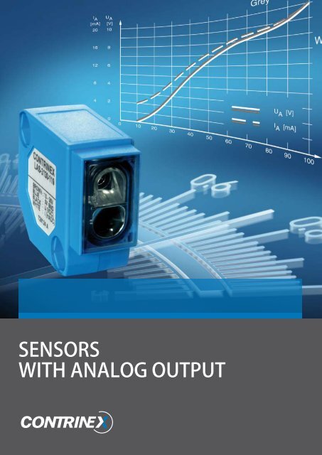
Sensors<br />
with analog output
INTRODUCTION<br />
<strong>SENSORS</strong> WITH ANALOG <strong>OUTPUT</strong><br />
Classical (switching) proximity switches work internally as analog devices, although they produce<br />
a binary signal at the output. A large part of the available internal information, though, is lost.<br />
Switches with analog outputs, on the other hand, provide the user with full information, permitting<br />
a variety of possible applications.<br />
Technology<br />
As mentioned above, proximity switches already work as analog devices. However, a signal<br />
shaper before the output stage changes the rectified analog signal into a digital one. This signal<br />
shaper also exists in switches with analog outputs, but there it serves an entirely different purpose.<br />
Instead of producing a switching point, it converts the signal emitted by the rectifier into a<br />
more usable, but still analog, form. Its main purpose is the generation of defined starting and end<br />
points of the output function, as well as a defined flow in between. Such switches have been available<br />
on the market for some time. The scope of their application has, however, so far remained<br />
very small, principally due to severe limitations of their usable sensing range.<br />
Advantages of analog<br />
technology<br />
- Very large sensing range<br />
- Available in an economical non-linearized<br />
execution with favorable transfer function<br />
- Low specimen scattering<br />
- Current and voltage output in the same device<br />
(most models)<br />
axle<br />
Application areas<br />
Contrinex proposes a number of inductive,<br />
photoelectric and ultrasonic devices with analog<br />
output. The use of analog sensor technology<br />
permits the realization of numerous applications.<br />
- The regulated approach to end positions at<br />
minimum cost<br />
- The realization of several switch points with<br />
a single device<br />
- Concentricity monitoring (Fig. 1)<br />
- Vibration monitoring<br />
Fig. 1<br />
signal<br />
For further application possibilities, please consult the Contrinex technical notes on sensors with<br />
analog output.<br />
U A<br />
t
Inductive analog devices<br />
Contrinex inductive analog sensors use Condist<br />
® technology for particularly large sensing<br />
ranges. In addition, these devices are characterized<br />
by good switching accuracy, stability,<br />
and repeat accuracy, as well as low specimen<br />
scattering.<br />
For most models, a voltage output (0 ... 5 V<br />
or 0 ... 10 V) and a current output (1 ... 5 mA<br />
or 4 ... 20 mA) are available simultaneously.<br />
Presently, all devices demonstrate non-linear<br />
transmission behaviour, as shown in Fig. 2 for<br />
DW-A#-509-M12.<br />
Fig. 2<br />
5<br />
4<br />
3<br />
2<br />
1<br />
U A [V]<br />
I<br />
A<br />
[mA]<br />
aluminum<br />
0<br />
0 1 2 3 4 5 6<br />
steel<br />
S [mm]<br />
PHOTOELECTRIC ANALOG DEVICES<br />
In order to enlarge its range of analog sensors, Contrinex now also offers photoelectric sensors<br />
with analog output. The devices feature a large sensing range, excellent temperature stability and<br />
an outstanding repeat accuracy. The sensing range is furthermore independent of the target color<br />
and surface structure. Since intermediate digitalisation has been dispensed with, the resolution<br />
of these sensors is virtually unlimited. In addition, their excellent white-gray characteristics allow<br />
for efficient background suppression.<br />
Ultrasonic analog devices<br />
Ultrasonic proximity switches can be used as contact-free sensors in many areas of automation.<br />
They are employed wherever distances have to be measured in air, since they not only detect<br />
objects, but they can also indicate and evaluate the absolute distance between themselves and<br />
the target. Changing atmospheric conditions, such as temperature variations for instance, are<br />
compensated during the evaluation process of the measurement. The ultrasonic range includes<br />
devices with analog and switching outputs.
INDUCTIVE ANALOG sensors<br />
Main features<br />
− Large usable sensing ranges<br />
− Excellent resolution (no digitalization)<br />
− Excellent temperature stability<br />
− Voltage as well as current outputs in the same device (most models)<br />
− Switch point setting by teach-in (in conjunction with a PLC)<br />
− Rectangular version (housing 8 x 8 x 50) for easier installation in limited spaces<br />
Technical data<br />
Housing material<br />
Supply voltage range U B<br />
Permissible ripple content<br />
No-load supply current<br />
Output voltage, damped<br />
Output voltage, non-damped<br />
Ambient temperature range<br />
Temperature drift % s r<br />
Degree of protection<br />
EMC protection:<br />
IEC 60947-5-2<br />
IEC 61000-4-2<br />
IEC 61000-4-3<br />
IEC 61000-4-4<br />
Short-circuit protection<br />
Polarity reversal protection<br />
Power-on reset<br />
Chrome-plated brass<br />
10 ... 30 / 15 ... 30 VDC*<br />
≤ 20 %<br />
≤ 10 mA<br />
0 VDC<br />
5 VDC / 10 VDC*<br />
-25 ... +70 °C**<br />
≤ 5 % (0 ... +70 °C)<br />
≤ 10 % (-25 ... 0 °C)<br />
IP 67<br />
5 kV<br />
Level 2<br />
Level 3<br />
Level 2<br />
Built-in<br />
Built-in<br />
Built-in<br />
* DW-A#-5#9-M##-320/39#<br />
** Depending on operating conditions, limited temperature range for DW-A#-509-M##-320/39# (see data sheets)<br />
Documentation<br />
Detailed data sheets for these products can be found on the CONTRINEX website www.contrinex.com<br />
or ordered free of charge from our distributors.<br />
Technical drawings can be downloaded as files from the CONTRINEX website and directly imported<br />
into your construction drawings.
4<br />
45<br />
SERIES 509 0 ... 4 mm 0 ... 4 mm 0 ... 4 mm 0 ... 4 mm<br />
M8x1<br />
M8x1<br />
SW 13<br />
SW 13<br />
60<br />
4<br />
Ø 3,5<br />
Ø 6,5<br />
8,5<br />
6<br />
Dimensions:<br />
M8x1<br />
Type specific data<br />
Housing size<br />
Sensing range<br />
Connection<br />
Bandwidth (-3 dB)<br />
Mounting<br />
Voltage output<br />
Current output<br />
8 x 8<br />
0 ... 4 mm<br />
PUR cable 2 m*<br />
1,600 Hz (at s = 2 mm)<br />
Quasi-embeddable<br />
0 ... 10 V<br />
---<br />
8 x 8<br />
0 ... 4 mm<br />
Connector S8 3-pole<br />
1,600 Hz (at s = 2 mm)<br />
Quasi-embeddable<br />
0 ... 10 V<br />
---<br />
M8<br />
0 ... 4 mm<br />
PUR cable 2 m*<br />
1,600 Hz (at s = 2 mm)<br />
Quasi-embeddable<br />
0 ... 5 V / 0 ... 10 V<br />
---<br />
M8<br />
0 ... 4 mm<br />
Connector S8 3-pole<br />
1,600 Hz (at s = 2 mm)<br />
Quasi-embeddable<br />
0 ... 5 V / 0 ... 10 V<br />
---<br />
part references<br />
Part ref.: (bold: preferred types)<br />
Non-linearized:<br />
Outputs 0...5 V / 1...5 mA<br />
---<br />
---<br />
DW-AD-509-M8<br />
DW-AS-509-M8-001<br />
Outputs 0...10 V / 4...20 mA<br />
DW-AD-509-C8-390<br />
DW-AS-509-C8-390<br />
DW-AD-509-M8-390<br />
DW-AS-509-M8-390<br />
Wiring (page 19)<br />
Diagram 1<br />
Diagram 1<br />
Diagram 1<br />
Diagram 1<br />
* Other cable lengths and types on request.
SERIES 509 0 ... 4 mm 0 ... 6 mm 0 ... 6 mm 0 ... 6 mm<br />
M8x1<br />
SW 13<br />
8<br />
22<br />
4<br />
66<br />
Ø 10,5<br />
Dimensions:<br />
M12x1<br />
Type specific data<br />
Housing size<br />
Sensing range<br />
Connection<br />
Bandwidth (-3 dB)<br />
Mounting<br />
Voltage output<br />
Current output<br />
M8<br />
0 ... 4 mm<br />
Connector S12 4-pole<br />
1,600 Hz (at s = 2 mm)<br />
Quasi-embeddable<br />
0 ... 5 V / 0 ... 10 V<br />
---<br />
M12<br />
0 ... 6 mm<br />
PUR cable 2 m*<br />
1,000 Hz (at s = 3 mm)<br />
Quasi-embeddable<br />
0 ... 5 V / 0 ... 10 V<br />
1 ... 5 mA<br />
M12<br />
0 ... 6 mm<br />
PUR cable 2 m*<br />
1,000 Hz (at s = 3 mm)<br />
Quasi-embeddable<br />
0 ... 5 V / 0 ... 10 V<br />
1 ... 5 mA / 4 ... 20 mA<br />
M12<br />
0 ... 6 mm<br />
Connector S12 4-pole<br />
1,000 Hz (at s = 3 mm)<br />
Quasi-embeddable<br />
0 ... 5 V / 0 ... 10 V<br />
1 ... 5 mA<br />
part references<br />
Part ref.: (bold: preferred types)<br />
Non-linearized:<br />
Outputs 0...5 V / 1...5 mA<br />
DW-AS-509-M8<br />
DW-AD-509-M12-120<br />
DW-AD-509-M12<br />
DW-AS-509-M12-120<br />
Outputs 0...10 V / 4...20 mA<br />
DW-AS-509-M8-393<br />
DW-AD-509-M12-320**<br />
DW-AD-509-M12-390<br />
DW-AS-509-M12-320**<br />
Wiring (page 19)<br />
Diagram 1<br />
Diagram 2<br />
* Other cable lengths and types on request. ** Without current output<br />
Diagram 2<br />
Diagram 2
0 ... 6 mm 0 ... 10 mm 0 ... 10 mm 0 ... 10 mm 0 ... 10 mm<br />
M12<br />
0 ... 6 mm<br />
Connector S12 4-pole<br />
1,000 Hz (at s = 3 mm)<br />
Quasi-embeddable<br />
0 ... 5 V / 0 ... 10 V<br />
1 ... 5 mA / 4 ... 20 mA<br />
M18<br />
0 ... 10 mm<br />
PUR cable 2 m*<br />
500 Hz (at s = 5 mm)<br />
Quasi-embeddable<br />
0 ... 5 V / 0 ... 10 V<br />
1 ... 5 mA / 4 ... 20 mA<br />
M18<br />
0 ... 10 mm<br />
PUR cable 2 m*<br />
500 Hz (at s = 5 mm)<br />
Quasi-embeddable<br />
0 ... 5 V / 0 ... 10 V<br />
1 ... 5 mA / 4 ... 20 mA<br />
M18<br />
0 ... 10 mm<br />
Connector S12 4-pole<br />
500 Hz (at s = 5 mm)<br />
Quasi-embeddable<br />
0 ... 5 V / 0 ... 10 V<br />
1 ... 5 mA / 4 ... 20 mA<br />
M18<br />
0 ... 10 mm<br />
Connector S12 4-pole<br />
500 Hz (at s = 5 mm)<br />
Quasi-embeddable<br />
0 ... 5 V / 0 ... 10 V<br />
1 ... 5 mA / 4 ... 20 mA<br />
DW-AS-509-M12<br />
DW-AD-509-M18-120<br />
DW-AD-509-M18<br />
DW-AS-509-M18-120<br />
DW-AS-509-M18-002<br />
DW-AS-509-M12-390<br />
DW-AD-509-M18-320<br />
DW-AD-509-M18-390<br />
DW-AS-509-M18-320<br />
DW-AS-509-M18-390<br />
Diagram 2<br />
Diagram 2<br />
Diagram 2<br />
Diagram 2<br />
Diagram 2
SERIES 509 0 ... 20 mm 0 ... 20 mm 0 ... 20 mm 0 ... 20 mm<br />
Dimensions:<br />
Type specific data<br />
Housing size<br />
Sensing range<br />
Connection<br />
Bandwidth (-3 dB)<br />
Mounting<br />
Voltage output<br />
Current output<br />
M30<br />
0 ... 20 mm<br />
PUR cable 2 m*<br />
200 Hz (at s = 10 mm)<br />
Quasi-embeddable<br />
0 ... 5 V / 0 ... 10 V<br />
1 ... 5 mA / 4 ... 20 mA<br />
M30<br />
0 ... 20 mm<br />
PUR cable 2 m*<br />
200 Hz (at s = 10 mm)<br />
Quasi-embeddable<br />
0 ... 5 V / 0 ... 10 V<br />
1 ... 5 mA / 4 ... 20 mA<br />
M30<br />
0 ... 20 mm<br />
Connector S12 4-pole<br />
200 Hz (at s = 10 mm)<br />
Quasi-embeddable<br />
0 ... 5 V / 0 ... 10 V<br />
1 ... 5 mA / 4 ... 20 mA<br />
M30<br />
0 ... 20 mm<br />
Connector S12 4-pole<br />
200 Hz (at s = 10 mm)<br />
Quasi-embeddable<br />
0 ... 5 V / 0 ... 10 V<br />
1 ... 5 mA / 4 ... 20 mA<br />
part references<br />
Part ref.: (bold: preferred types)<br />
Non-linearized:<br />
Outputs 0...5 V / 1...5 mA<br />
DW-AD-509-M30-120<br />
DW-AD-509-M30<br />
DW-AS-509-M30-120<br />
DW-AS-509-M30-002<br />
Outputs 0...10 V / 4...20 mA<br />
DW-AD-509-M30-320<br />
DW-AD-509-M30-390<br />
DW-AS-509-M30-320<br />
DW-AS-509-M30-390<br />
Wiring (page 19)<br />
Diagram 2<br />
Diagram 2<br />
Diagram 2<br />
Diagram 2<br />
* Other cable lengths and types on request.
0 ... 40 mm 0 ... 40 mm<br />
0 ... 40 mm 0 ... 40 mm<br />
M30<br />
0 ... 40 mm<br />
PUR cable 2 m*<br />
100 Hz (at s = 20 mm)<br />
Non-embeddable<br />
0 ... 5 V / 0 ... 10 V<br />
1 ... 5 mA / 4 ... 20 mA<br />
M30<br />
0 ... 40 mm<br />
PUR cable 2 m*<br />
100 Hz (at s = 20 mm)<br />
Non-embeddable<br />
0 ... 5 V / 0 ... 10 V<br />
1 ... 5 mA / 4 ... 20 mA<br />
M30<br />
0 ... 40 mm<br />
Connector S12 4-pole<br />
100 Hz (at s = 20 mm)<br />
Non-embeddable<br />
0 ... 5 V / 0 ... 10 V<br />
1 ... 5 mA / 4 ... 20 mA<br />
M30<br />
0 ... 40 mm<br />
Connector S12 4-pole<br />
100 Hz (at s = 20 mm)<br />
Non-embeddable<br />
0 ... 5 V / 0 ... 10 V<br />
1 ... 5 mA / 4 ... 20 mA<br />
DW-AD-519-M30-120<br />
DW-AD-519-M30<br />
DW-AS-519-M30-120<br />
DW-AS-519-M30-002<br />
DW-AD-519-M30-320<br />
DW-AD-519-M30-390<br />
DW-AS-519-M30-320<br />
DW-AS-519-M30-390<br />
Diagram 2<br />
Diagram 2<br />
Diagram 2<br />
Diagram 2
photoelectric ANALOG<br />
diffuse sensors<br />
Main features<br />
- Small housing size<br />
− Sensing range from 10 ...100 mm<br />
− Excellent resolution<br />
− Excellent temperature stability<br />
− Voltage output of 0 ... 5 V<br />
− Operating distance independent of target color and surface structure<br />
− Bandwidth of 100 Hz<br />
− Glass lens, easy to clean<br />
Technical data<br />
Housing material<br />
Supply voltage range U B<br />
Permissible ripple content<br />
No-load supply current<br />
Time delay before availability<br />
Max. ambient light:<br />
halogen<br />
sun<br />
Ambient temperature range<br />
Temperature drift % s n<br />
Degree of protection<br />
EMC protection:<br />
IEC 60947-5-2<br />
IEC 61000-4-2<br />
IEC 61000-4-3<br />
IEC 61000-4-4<br />
IEC 61000-4-6<br />
Short-circuit protection<br />
Polarity reversal protection<br />
Power-on reset<br />
Chrome-plated brass<br />
10 ... 30 VDC<br />
≤ 20 %<br />
≤ 25 mA<br />
≤ 100 msec<br />
5,000 Lux<br />
10,000 Lux<br />
0 ... +55 °C<br />
0.1 / °C<br />
IP 67<br />
1 kV<br />
Level 2<br />
Level 2<br />
Level 3<br />
Level 2<br />
Built-in<br />
Built-in<br />
Built-in<br />
Documentation<br />
Detailed data sheets for these products can be found on the CONTRINEX website www.contrinex.com<br />
or ordered free of charge from our distributors.<br />
Technical drawings can be downloaded as files from the CONTRINEX website and directly imported<br />
into your construction drawings.
SERIES 1120<br />
10 ... 100 mm<br />
gray<br />
white<br />
black<br />
Response curve:<br />
Type specific data<br />
Housing size<br />
Sensing range<br />
Standard target<br />
Bandwidth (-3 dB)<br />
Emitter<br />
Voltage output<br />
Current output<br />
M12<br />
10 ... 100 mm<br />
100 x 100 mm white<br />
100 Hz (at s = 50 mm)<br />
LED red 660 nm<br />
0 ... 5 V<br />
---<br />
part references<br />
Part ref.: (bold: preferred types)<br />
Output 0 ... 5 V / PVC cable 2 m*<br />
Wiring (page 19)<br />
* Other cable lengths and types on request.<br />
LAK-1120-309<br />
Diagram 1
photoelectric ANALOG<br />
diffuse sensors<br />
Main features<br />
− Sensing range from 10 ... 100 mm<br />
− Excellent resolution (no digitalization)<br />
− Excellent temperature stability<br />
− Voltage as well as current outputs in the same device<br />
− Operating distance independent of target color and surface structure<br />
− Bandwidth of 500 Hz<br />
− Glass window, easy to clean<br />
− Extremely resistant and fully-potted PBTP (Crastin) housing<br />
Technical data<br />
Housing material<br />
Supply voltage range U B<br />
Permissible ripple content<br />
No-load supply current<br />
Time delay before availability<br />
Max ambient light:<br />
halogen<br />
sun<br />
Ambient temperature range<br />
Temperature drift % s n<br />
Degree of protection<br />
EMC protection:<br />
IEC 60947-5-2<br />
IEC 61000-4-2<br />
IEC 61000-4-3<br />
IEC 61000-4-4<br />
IEC 61000-4-6<br />
Short-circuit protection<br />
Polarity reversal protection<br />
Power-on reset<br />
Glass-fiber reinforced PBTP (Crastin)<br />
10 ... 36 VDC / 15 ... 36 VDC (LA#-3130-119)<br />
≤ 20 %<br />
≤ 25 mA<br />
≤ 100 msec<br />
5,000 Lux<br />
10,000 Lux<br />
-25 ... +55 °C<br />
0.1 / °C<br />
IP 67<br />
5 kV<br />
Level 3<br />
Level 3<br />
Level 3<br />
Level 2<br />
Built-in<br />
Built-in<br />
Built-in<br />
Documentation<br />
Detailed data sheets for these products can be found on the CONTRINEX website www.contrinex.com<br />
or ordered free of charge from our distributors.<br />
Technical drawings can be downloaded as files from the CONTRINEX website and directly imported<br />
into your construction drawings.
SERIES 3130 10 ... 100 mm 10 ... 100 mm<br />
black<br />
gray<br />
white<br />
black<br />
gray<br />
white<br />
Response curves:<br />
Type specific data<br />
Housing size<br />
Sensing range<br />
Standard target<br />
Bandwidth (-3 dB)<br />
Emitter<br />
Voltage output<br />
Current output<br />
30 x 30 x 15<br />
10 ... 100 mm<br />
100 x 100 mm white<br />
500 Hz (at s = 50 mm)<br />
LED red 660 nm<br />
0 ... 5 V<br />
1 ... 5 mA<br />
30 x 30 x 15<br />
10 ... 100 mm<br />
100 x 100 mm white<br />
500 Hz (at s = 50 mm)<br />
LED red 660 nm<br />
0 ... 10 V<br />
4 ... 20 mA<br />
part references<br />
Part ref.: (bold: preferred types)<br />
Voltage and current outputs / PVC cable 2 m*<br />
Voltage and current outputs / Connector S8 4-pole<br />
Wiring (page 19)<br />
* Other cable lengths and types on request.<br />
LAK-3130-109<br />
LAS-3130-109<br />
Diagram 2<br />
LAK-3130-119<br />
LAS-3130-119<br />
Diagram 2
ultrasonic ANALOG<br />
sensors<br />
Main features<br />
− Ready-to-connect compact devices<br />
− Can be operated as diffuse or reflex sensors<br />
− High excess gain, therefore insensitive to dirt and ambient noise<br />
− Detection independent of target color, shape, material and surface structure<br />
− Reduced blind zone<br />
− Low current drain<br />
− Adjustment by means of interface device APE-0000-001<br />
− Fore- and background suppression<br />
− Diffuse sensors with window function<br />
− High degree of protection: IP 67<br />
Technical data<br />
Housing material<br />
Supply voltage range U B<br />
Permissible ripple content<br />
Current output<br />
No-load supply current<br />
Time delay before availability<br />
Ambient temperature range<br />
Degree of protection<br />
EMC protection:<br />
IEC 61000-4-2<br />
IEC 61000-4-3<br />
IEC 61000-4-4<br />
IEC 61000-4-6<br />
EN 55011<br />
Short-circuit protection<br />
Polarity reversal protection<br />
Power-on reset<br />
Nickel-plated brass<br />
12 ... 30 VDC*<br />
≤ 10 %<br />
4 ... 20 mA<br />
≤ 50 mA<br />
280 msec<br />
-25 ... +70 °C<br />
IP 67<br />
4 kV<br />
10 V/m<br />
2 kV<br />
10 V<br />
Class B<br />
Built-in<br />
Built-in<br />
Built-in<br />
* At 12 ... 20 V, approx. 20 % reduced sensing range<br />
LED<br />
The yellow LED lights up when the output is switched. Flashing LED indicates misadjustment.<br />
Documentation<br />
Detailed data sheets for these products can be found on the CONTRINEX website www.contrinex.com<br />
or ordered free of charge from our distributors.<br />
Technical drawings can be downloaded as files from the CONTRINEX website and directly imported<br />
into your construction drawings.
101<br />
65<br />
14<br />
SW 24<br />
90,5<br />
SERIES 1180/1181<br />
50 ... 300 mm<br />
150 ... 1,000 mm<br />
M18x1<br />
M18x1<br />
101<br />
SW 24<br />
90,5<br />
65<br />
4<br />
4<br />
14<br />
LED (4x)<br />
LED (4x)<br />
Dimensions:<br />
M12x1<br />
M12x1<br />
Type specific data<br />
Housing size<br />
Sensing range<br />
Setting range<br />
Standard target<br />
Hysteresis<br />
Rated ultrasonic frequency<br />
Response time<br />
Voltage output<br />
Current output<br />
M18<br />
50 ... 300 mm<br />
70 ... 300 mm<br />
10 x 10 mm<br />
10 mm<br />
400 kHz<br />
100 msec<br />
---<br />
4 ... 20 mA<br />
M18<br />
150 ... 1,000 mm<br />
170 ... 1,000 mm<br />
20 x 20 mm<br />
10 mm<br />
200 kHz<br />
120 msec<br />
---<br />
4 ... 20 mA<br />
part references<br />
Part ref.: (bold: preferred types)<br />
Output 4 ... 20 mA / Connector S12 4-pole<br />
Wiring (page 19)<br />
UTS-1180-329<br />
Diagram 3<br />
UTS-1181-329<br />
Diagram 3
ultrasonic ANALOG<br />
sensors<br />
Main features<br />
− Ready-to-connect compact devices<br />
− Can be operated as diffuse or reflex sensors<br />
− High excess gain, therefore insensitive to dirt and ambient noise<br />
− Detection independent of target color, shape, material and surface structure<br />
− Reduced blind zone<br />
− Low current drain<br />
− Adjustment by means of potentiometers and interface device APE-0000-001<br />
− Switching and analog outputs<br />
− Fore- and background suppression<br />
− Diffuse sensors with window function<br />
− High degree of protection: IP 65<br />
Technical data<br />
Housing material<br />
Supply voltage range U B<br />
Permissible ripple content<br />
Output current<br />
Output voltage drop<br />
No-load supply current<br />
Time delay before availability<br />
Ambient temperature range<br />
Degree of protection<br />
EMC protection:<br />
IEC 61000-4-2<br />
IEC 61000-4-3<br />
IEC 61000-4-4<br />
IEC 61000-4-6<br />
EN 55011<br />
Short-circuit protection<br />
Polarity reversal protection<br />
Power-on reset<br />
Nickel-plated brass<br />
12 ... 30 VDC*<br />
≤ 10 %<br />
300 mA max.<br />
3.0 V max. at 300 mA<br />
≤ 60 mA<br />
280 msec<br />
-25 ... +70 °C<br />
IP 65<br />
4 kV<br />
10 V/m<br />
2 kV<br />
10 V<br />
Class B<br />
Built-in<br />
Built-in<br />
Built-in<br />
* At 12 ... 20 V, approx. 20 % reduced sensing range<br />
LED<br />
The yellow LED lights up when the output is switched. Flashing LED indicates misadjustment.<br />
Documentation<br />
Detailed data sheets for these products can be found on the CONTRINEX website www.contrinex.com<br />
or ordered free of charge from our distributors.<br />
Technical drawings can be downloaded as files from the CONTRINEX website and directly imported<br />
into your construction drawings.
SERIES 1300...1303<br />
60 ... 300 mm<br />
200 ... 1,300 mm<br />
400 ... 3,000 mm<br />
600 ... 6,000 mm<br />
M30x1,5<br />
M30x1,5<br />
Ø 47,5<br />
Ø 65<br />
80<br />
80<br />
33<br />
19<br />
5<br />
5<br />
Ø 34<br />
5<br />
36<br />
22<br />
Ø 34<br />
131<br />
POT min.<br />
SW 36<br />
Ø 27,5<br />
LED<br />
POT max.<br />
14<br />
131<br />
SW 36<br />
POT min.<br />
Ø 27,5<br />
LED<br />
POT max.<br />
14<br />
150<br />
SW 36<br />
POT min.<br />
M30x1,5<br />
Ø 27,5<br />
99<br />
LED<br />
POT max.<br />
153<br />
SW 36<br />
POT min.<br />
M30x1,5<br />
Ø 27,5<br />
5<br />
102<br />
LED<br />
POT max.<br />
Dimensions:<br />
M12x1<br />
Ø 26<br />
10,5<br />
M12x1<br />
Ø 26<br />
10,5<br />
M12x1<br />
Ø 26<br />
14<br />
10,5<br />
M12x1<br />
Ø 26<br />
14<br />
10,5<br />
Type specific data<br />
Housing size<br />
Sensing range<br />
Setting range<br />
Standard target<br />
Hysteresis<br />
Rated ultrasonic frequency<br />
Switching frequency<br />
Response time<br />
Voltage output<br />
Current output<br />
M30<br />
60 ... 300 mm<br />
80 ... 300 mm<br />
10 x 10 mm<br />
10 mm<br />
400 kHz<br />
5 Hz<br />
100 msec<br />
0 ... 10 V<br />
4 ... 20 mA<br />
M30<br />
200 ... 1,300 mm<br />
220 ... 1,300 mm<br />
20 x 20 mm<br />
10 mm<br />
200 kHz<br />
4 Hz<br />
120 msec<br />
0 ... 10 V<br />
4 ... 20 mA<br />
M30<br />
400 ... 3,000 mm<br />
420 ... 3,000 mm<br />
50 x 50 mm<br />
20 mm<br />
120 kHz<br />
2 Hz<br />
200 msec<br />
0 ... 10 V<br />
4 ... 20 mA<br />
M30<br />
600 ... 6,000 mm<br />
640 ... 6,000 mm<br />
100 x 100 mm<br />
60 mm<br />
80 kHz<br />
1 Hz<br />
400 msec<br />
0 ... 10 V<br />
4 ... 20 mA<br />
part references<br />
Part ref.: (bold: preferred types)<br />
4...20 mA + PNP N.O. / S12 5-p.<br />
0...10 V + PNP N.O. / S12 5-p.<br />
UTS-1300-123<br />
UTS-1300-113<br />
UTS-1301-123<br />
UTS-1301-113<br />
UTS-1302-123<br />
UTS-1302-113<br />
UTS-1303-123<br />
UTS-1303-113<br />
Wiring (page 19)<br />
Diagram 4 (-123) / 5 (-113)<br />
Diagram 4 (-123) / 5 (-113)<br />
Diagram 4 (-123) / 5 (-113)<br />
Diagram 4 (-123) / 5 (-113)
accessories<br />
for ultrasonic sensors<br />
CONPROG PC interface<br />
For optimum adaptation to the application conditions, the parameters of all ultrasonic devices in<br />
this catalog can be programmed, visualized, checked and changed with the PC interface device<br />
APE-0000-001 and its software CONPROG. Amongst others, the following parameters can be<br />
set:<br />
− Beginning and end of operating range<br />
− Hysteresis<br />
− End of sensing range<br />
− Switching function (N.O. or N.C.)<br />
− Beginning and end of analog characteristic curve<br />
− Direction of analog characteristic curve (rising or falling)<br />
− End of blind zone<br />
− Mean value generation<br />
− Temperature compensation<br />
− Multiplex function<br />
− Function as diffuse or reflex sensor<br />
− Switching frequency<br />
− Damping (sensitivity)<br />
The programmed values can be stored and printed, thus simplifying the maintenance and documentation<br />
of the installation. In case several sensors need to be parametrized identically, the<br />
stored setting values can be transferred rapidly to the other sensors by means of the interface<br />
device (e.g. when connecting switches in series, or when exchanging them).<br />
The interface device is delivered with a RS232 cable (for serial interface), a mains transformer<br />
plug, a sensor connecting cable and CONPROG PC software for Windows. Updates to the latest<br />
software version can be downloaded from the CONTRINEX website (www.contrinex.com).<br />
part references<br />
Interface device<br />
APE-0000-001
wiring diagrams<br />
brown<br />
black<br />
load<br />
Diagram 1 Diagram 2<br />
brown<br />
black<br />
white*<br />
load<br />
blue<br />
blue<br />
* Only for models with current output<br />
brown<br />
(1)<br />
+U<br />
B<br />
Diagram 3<br />
black<br />
(4)<br />
A<br />
load<br />
white<br />
(2)<br />
XI<br />
R L<br />
blue<br />
(3)<br />
0V<br />
brown<br />
(1)<br />
+U<br />
B<br />
brown<br />
(1)<br />
+U<br />
B<br />
black<br />
(4)<br />
A1<br />
load<br />
black<br />
(4)<br />
A1<br />
load<br />
Diagram 4<br />
white<br />
blue<br />
(2)<br />
(3)<br />
XI<br />
0V<br />
R<br />
Diagram 5<br />
white<br />
blue<br />
(2)<br />
(3)<br />
XI<br />
0V<br />
R<br />
R<br />
R<br />
gray<br />
(5)<br />
A2<br />
gray<br />
(5)<br />
A2
all over the world<br />
Europe<br />
Austria<br />
Belgium<br />
Croatia<br />
Czech Republic<br />
Denmark<br />
Finland<br />
France<br />
Germany<br />
Great Britain<br />
Greece<br />
Hungary<br />
Ireland<br />
Italy<br />
Luxembourg<br />
Netherlands<br />
Norway<br />
Poland<br />
Portugal<br />
Romania<br />
Russian Federation<br />
Slovakia<br />
Slovenia<br />
Spain<br />
Sweden<br />
Switzerland<br />
Turkey<br />
Africa<br />
South Africa<br />
The Americas<br />
Argentina<br />
Brazil<br />
Canada<br />
Chile<br />
Colombia<br />
Mexico<br />
United States<br />
Venezuela<br />
Asia<br />
China<br />
India<br />
Indonesia<br />
Japan<br />
Korea<br />
Malaysia<br />
Pakistan<br />
Philippines<br />
Singapore<br />
Taiwan<br />
Thailand<br />
Vietnam<br />
Australasia<br />
Australia<br />
New Zealand<br />
Middle East<br />
Iran<br />
Israel<br />
Syria<br />
United Arab Emirates<br />
019 002 - isp 09.08 - 2,000
Industrial Safety Sales<br />
I N C O R P O R A T E D<br />
INDUSTRIAL<br />
SAFETY SALES INC.<br />
P.O. Box 126 -- 4112 Sheridan Road<br />
Kenosha, WI 53141<br />
Fax: (262) 652-1388<br />
E-mail: safetysensing@earthlink.net<br />
(262) 652-8660