The Soilfrac® Process - Smet-Keller
The Soilfrac® Process - Smet-Keller
The Soilfrac® Process - Smet-Keller

You also want an ePaper? Increase the reach of your titles
YUMPU automatically turns print PDFs into web optimized ePapers that Google loves.
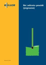
Brochure 61- 02 E<br />
<strong>The</strong> Soilfrac ®<br />
<strong>Process</strong>
CONTENTS<br />
Soilfrac®-today . . . . . . . . . . . . . . . . 2<br />
Soilfrac-<strong>Process</strong> Description . . . . . . . . 4<br />
Soilfrac-Foundation Restoration . . . . . 6<br />
Soilfrac-Lifting of Structures . . . . . . . 8<br />
Soilfrac-Protection of Structures . . . . 10
Development<br />
Originally the Soilfracturing process was used in the oil industry to<br />
frac sub soils to create paths for the oil to flow toward the oil wells.<br />
In the sixties, <strong>Keller</strong> engineers adapted this process and developed<br />
several solutions to problems in the geotechnical field. Soilfrac® is a<br />
registered Trademark of the process used by <strong>Keller</strong>.<br />
Position in the market<br />
Where classical grouting techniques for voidfilling for foundations<br />
or restoration of structures is not suitable or the lifting of structures<br />
is required, the Soilfrac-process fills the gap within the circle of<br />
different grouting techniques.<br />
Together with the newly developed measuring and control techniques<br />
as well as special observation devices it is possible to lift structures<br />
by several decimeters.<br />
Soilfrac ® today<br />
3
<strong>The</strong> Soilfrac® <strong>Process</strong><br />
In using this process fractures in the soil are created which are then<br />
filled with grout. Each soil formation may be improved by multiple<br />
grouting treatments and controlled lifting may be induced.<br />
<strong>Process</strong><br />
Application limits for the grouting processes<br />
<strong>Process</strong><br />
Clay Silt<br />
Sand Gravel Cobbles<br />
100<br />
Soilfrac®<br />
Soilcrete-Jet Grouting®<br />
80<br />
Compaction Grouting<br />
Synthetic Solutions<br />
60<br />
Sodium Silicate Solutions (lv)<br />
Silicate Gel (hv)<br />
40<br />
Ultrafine Cement<br />
Cement suspension<br />
20<br />
Mortar<br />
0<br />
lv = low viscous<br />
0,002 0,006 0,02 0,06 0,2 0,6 2,0 6,0 20 60<br />
hv = high viscous Partical size (mm)<br />
Passing-Weight (%)<br />
uneconomical<br />
favourable<br />
Installation point<br />
basement<br />
Installation point shaft<br />
Installation point ground<br />
surface<br />
4
Construction site<br />
installation<br />
Water<br />
Cement-Filler<br />
Stone dust<br />
Accelerator<br />
and Additives<br />
Mixer and<br />
pump<br />
Measuring<br />
and control<br />
▲ Mixing- and grout<br />
station placed into a<br />
Soilfrac®-container<br />
allowing short installation<br />
period.<br />
Installation point<br />
1 2 3<br />
1 Sleeve pipe<br />
installation<br />
Sleeve pipes are installed<br />
into the soil formation<br />
to be treated and the<br />
annular space between<br />
the borehole wall and<br />
sleeve pipe sealed with<br />
a stiff cement-bentonite<br />
mixture.<br />
2 Soil fracturing<br />
To allow the injection of<br />
the Soilfrac® suspension<br />
a grout hose equipped<br />
with a double packer at<br />
the tip is inserted into<br />
the sleeve pipe. <strong>The</strong><br />
double packer seals the<br />
sleeve pipe on either<br />
side of the sleeve, thus<br />
allowing the grouting of<br />
each single sleeve along<br />
the section to be<br />
treated.<br />
3 Multiple grouting<br />
<strong>The</strong> sleeves along the<br />
grout pipe may be<br />
grouted once – or<br />
several times- according<br />
to the technical<br />
requirements. <strong>The</strong> grout<br />
quantity, the max. grout<br />
pressure – and in case<br />
of repeated grouting –<br />
the setting times are<br />
maintained according to<br />
instructions. Sleeve pipes<br />
may remain reusable<br />
for long periods.<br />
2<br />
4<br />
3<br />
1<br />
1 Sleeve pipe<br />
2 Sealing mix<br />
3 Rubber sleeve<br />
4 Grout<br />
5 Packer<br />
5<br />
Primary grouting<br />
Multiple grouting<br />
5
1 Restoration of the<br />
steeple as well as cement<br />
stabilisation of the nave in<br />
soil formation consisting of<br />
silt and peat.<br />
2 Foundation rehabilitation<br />
of a customs hut<br />
founded on top of fill<br />
material in a moat.<br />
3 Modern software is<br />
used for simulation and<br />
control of the Soilfrac® –<br />
works.<br />
Foundation Restoration<br />
Individual footings and subsoils are components of the foundation of a<br />
structure. In the course of time both may fail due to a number of<br />
reasons. This occurs quite often in the case of historical buildings.<br />
In the event of excessive settlements – Soilfrac® is a suitable process<br />
to restore the link between the base of the structure and<br />
competent soil formation.<br />
For the treatment of natural stone foundations, which have either<br />
moved or cracked or the mortar has decomposed or been removed,<br />
the classical grouting technique may be applied by adapting the type<br />
of grout mix. Lifting of structures in a poor condition is seldom<br />
required – but also possible.<br />
Specific working parameters<br />
are illustrated separately<br />
A Grid<br />
B Deformation foundation level<br />
C Grout pressure<br />
D Grout quantity<br />
E Foundation<br />
F Sleeve pipe fan<br />
Restoration<br />
1 2<br />
A<br />
B<br />
3<br />
C<br />
D<br />
E<br />
F<br />
<strong>The</strong> Soilfrac®-process is used for foundation restoration where settlements<br />
have to be stopped such as, where natural and artificial soil distortion occurs,<br />
mining activities create problems, non-load bearing soil exists, or partial<br />
sections must be lifted.<br />
6
Restoration of the<br />
steeple by means of<br />
the Soilfrac®-process<br />
and cement stabilisation<br />
of the nave.<br />
7
Lifting of Structures<br />
Settlement of structures can be rectified by the Soilfrac®-process.<br />
Depending to the condition of the building and the soil the lifting speed<br />
is adjusted accordingly.<br />
Precise partial lifting within a millimeter is combined and added to<br />
a total lifting in the decimeter range without damaging the structure.<br />
Lifting of structures is normally performed without restricting<br />
their use.<br />
1 Insertion of the grout<br />
hose into the sleeve pipe.<br />
2 Partial repositioning and<br />
rehabilitation of the river<br />
pier of a highway – bridge.<br />
3 Lifting of the discharge<br />
ramp of a refuse<br />
incineration plant.<br />
Lifting<br />
1 2<br />
3<br />
Restoring leaning structures to a vertical position is a spectacular event such<br />
as the efforts in connection with the leaning tower of Pisa. In some cases<br />
only a partial restoration is sufficient to achieve a satisfactory technical result<br />
as well as improving the esthetic view of the structure.<br />
8
High rise building<br />
restored to the vertical<br />
position<br />
Preparatory works for<br />
an extension caused the<br />
leaning of a high rise<br />
building.<br />
After installation of an<br />
extensive control point<br />
system to measure the<br />
vertical movements a<br />
sleeve pipe fan was<br />
installed in accordance<br />
with the lifting<br />
requirements. Within<br />
5 month a total lifting of<br />
60 mm was achieved.<br />
9
1 Installation of sleeve<br />
pipes from a temporary<br />
shaft.<br />
2 Sectional excavation of<br />
a tunnel to minimise<br />
settlements.<br />
3 Representation of<br />
prelifting in mirror image<br />
form of the estimated<br />
settlement trough within<br />
structural limits as well as<br />
the permanent uplift to<br />
secure the structure above<br />
the tunnel line.<br />
Protection of Structures<br />
To protect structures against predictable settlements during tunnel<br />
construction horizontal sleeve pipe fans between tunnel roof and the<br />
building foundation will be installed from temporarily shafts. <strong>The</strong><br />
building to be protected will be equipped with an electronic measuring<br />
system for registration of vertical movements.<br />
Primary grouting - up to appearance of lifting tendencies-consolidate<br />
the soil mass, followed by a predetermined lifting operation reflecting<br />
the size and form of the expected settlement trough due to tunnel<br />
driving.<br />
According to the local situation the tunnel will be excavated in one<br />
operation or in a number of segments. <strong>The</strong> settlement occuring during<br />
the tunneling works will be adjusted – either partially or to the full<br />
amount. <strong>The</strong> quick reaction in respect of the developing deformations<br />
reduces larger differential tensions within the structures, an advantage<br />
of the Soilfrac® process compared with other technical solutions.<br />
A Settlement prediction<br />
B Pre – Lifting<br />
C Interim settlement<br />
D Interim Lifting<br />
E Final position<br />
Protection<br />
1 2 3<br />
A<br />
B<br />
C<br />
D<br />
E<br />
<strong>The</strong> protection of structures against settlements from tunnel and mining<br />
activities is an important application of the Soilfrac® - process. This technique<br />
was used for the first time by <strong>Keller</strong> for a subway<br />
project in the Ruhr area of Germany in 1985.<br />
10
Structure protection during<br />
subway construction in a<br />
large European city.<br />
Installation of horizontally<br />
located sleeve pipes from<br />
shafts to protect the old<br />
town.<br />
11
<strong>Keller</strong> Grundbau GmbH<br />
International Geotechnical Contractors<br />
www.<strong>Keller</strong>Grundbau.com · www.<strong>Keller</strong>-Asia.com<br />
Germany<br />
Head Office and Overseas Division<br />
P.O. Box 10 06 64<br />
63006 Offenbach<br />
Tel. +49 69 8051-0 · Fax +49 69 8051-270<br />
E-mail: Overseas@<strong>Keller</strong>Grundbau.com<br />
Bahrain<br />
<strong>Keller</strong> Grundbau GmbH<br />
Flat 205, Bldg. 63<br />
P.O. Box 5452<br />
Manama 332<br />
Tel. +973 17741677 · Fax +973 17741688<br />
E-mail: <strong>Keller</strong>@batelco.com.bh<br />
U.A.E.<br />
<strong>Keller</strong> Grundbau GmbH<br />
Office No. 407<br />
H. H. Shaikh Ahmed Bin Saeed Al Maktoum Tower<br />
Shaikh Zayed Road · P.O. Box 11 13 23<br />
Dubai<br />
Tel. +971 4 329-8089 · Fax +971 4 329-8099<br />
E-mail: info@kellergrundbau.ae<br />
Saudi Arabia<br />
<strong>Keller</strong> Turki Co. Ltd.<br />
P.O. Box 718<br />
Dammam 31421<br />
Tel. +966 3 8333997 · Fax +966 3 8335325<br />
E-mail: <strong>Keller</strong>-turki@atco.com.sa<br />
Egypt<br />
GENCO · Geotechnical Engineering Contractor Ltd.<br />
462, Horreya Avenue, Roushdy<br />
Alexandria<br />
Tel. +20 3 5458443 · Fax +20 3 5427372<br />
E-mail: Genco-alx@link.net<br />
Malaysia<br />
<strong>Keller</strong> (M) Sdn. Bhd.<br />
B-5-10 Plaza Dwitasik<br />
Bandar Sri Permaisuri<br />
56000 Cheras, Kuala Lumpur<br />
Tel. +60 3 91733198 · Fax +60 3 91733196<br />
E-mail: info@keller.com.my<br />
Singapore<br />
<strong>Keller</strong> Foundations (S E Asia) Pte Ltd.<br />
18 Boon Lay Way<br />
#04-104 Tradehub 21<br />
Singapore 609966<br />
Tel. +65 6316-8500 · Fax +65 6316-8652<br />
E-mail: <strong>Keller</strong>@singnet.com.sg<br />
India<br />
<strong>Keller</strong> Ground Engineering India Pvt. Ltd.<br />
S-15, Economist House<br />
First Cross Road, Guindy Industrial Estate<br />
Chennai – 600032<br />
Tel. +91 44 2250185-0 /-1 · Fax +91 44 22501852<br />
E-mail: info@kellerindia.com<br />
A company of <strong>Keller</strong> Group plc