Design and validation of jet grouting for the ... - Smet-Keller
Design and validation of jet grouting for the ... - Smet-Keller
Design and validation of jet grouting for the ... - Smet-Keller

Create successful ePaper yourself
Turn your PDF publications into a flip-book with our unique Google optimized e-Paper software.
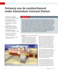
<strong>Design</strong> <strong>and</strong> <strong>validation</strong> <strong>of</strong> <strong>jet</strong><strong>grouting</strong> <strong>for</strong> <strong>the</strong> Amsterdam Central Station<br />
\ Figure 1 Schematic layout <strong>of</strong> <strong>the</strong> wall<br />
The columns were <strong>jet</strong>ted to a level <strong>of</strong> NAP –28<br />
m, approximately 29 m below ground level.<br />
The results <strong>of</strong> <strong>the</strong> trial suggested that <strong>the</strong>re<br />
was some scatter in diameter <strong>and</strong> that <strong>the</strong><br />
required strength might be difficult to achieve.<br />
The main philosophy <strong>of</strong> this trial was to carry<br />
out <strong>the</strong> <strong>jet</strong> <strong>grouting</strong> with both a pre-cut or prewashing<br />
phase followed by a fur<strong>the</strong>r <strong>jet</strong> grout<br />
phase. The initial pre-cut phase was to <strong>the</strong>oretically<br />
enlarge <strong>the</strong> hole to around a diameter <strong>of</strong><br />
40 cm <strong>and</strong> thus allow <strong>for</strong> improved spoil return<br />
<strong>and</strong> less material to be cut with <strong>the</strong> follow on<br />
<strong>jet</strong> grout phase. The measurements <strong>of</strong> diameter<br />
by both column callipers <strong>and</strong> <strong>the</strong> hydrophones<br />
gave some confidence that <strong>the</strong> required diameter<br />
had been achieved but strength was on <strong>the</strong><br />
low side. Following this trial <strong>the</strong> design <strong>of</strong> <strong>the</strong><br />
s<strong>and</strong>wich wall was re-evaluated <strong>and</strong> a lower<br />
design strength resulted. This assisted <strong>the</strong> <strong>jet</strong><br />
grout process but ultimately it was decided by<br />
<strong>the</strong> steering group that <strong>the</strong> most satisfactory<br />
solution could be obtained by carrying out a<br />
pre-cut with significantly higher energy to<br />
actually construct <strong>the</strong> column diameter with<br />
this phase. The <strong>jet</strong> grout phase was <strong>the</strong>n used<br />
to create a high cement content by <strong>the</strong> injection<br />
<strong>of</strong> a low water cement ratio grout. This methodology<br />
has <strong>the</strong> benefit that lower pump power<br />
is required <strong>for</strong> <strong>the</strong> pre-cut phase to achieve <strong>the</strong><br />
high pressures <strong>and</strong> flows required <strong>and</strong> that <strong>the</strong><br />
heavy <strong>jet</strong> grout grout injected was more liable<br />
to displace <strong>the</strong> lighter pre-cut spoil <strong>and</strong> give an<br />
enhanced strength through displacement<br />
ra<strong>the</strong>r than mixing. Following this change in<br />
methodology it was concluded that a fur<strong>the</strong>r<br />
small scale trial was required to validate <strong>the</strong><br />
new approach <strong>and</strong> in May 2005, five fur<strong>the</strong>r<br />
columns were constructed using <strong>the</strong> higher<br />
energy pre-cut with grouts <strong>of</strong> differing density.<br />
The column calliper, spoil density <strong>and</strong> hydro-<br />
phones were used again to validate diameters<br />
achieved. The results <strong>of</strong> this trial indicated that<br />
<strong>the</strong> high energy pre-cut was successful but that<br />
a lower water cement ratio grout was needed to<br />
ensure that <strong>the</strong> clay material was lifted out <strong>of</strong><br />
<strong>the</strong> columns.<br />
Column production<br />
The steering group considered that <strong>the</strong> production<br />
<strong>of</strong> each column needed very careful quality<br />
control <strong>and</strong> <strong>validation</strong> to ensure that <strong>the</strong><br />
integrity <strong>of</strong> <strong>the</strong> s<strong>and</strong>wich wall would not be<br />
compromised. It was <strong>the</strong>re<strong>for</strong>e agreed that <strong>the</strong><br />
following general sequence would be adopted.<br />
Drilling<br />
The drilling <strong>of</strong> each column was regulated to a<br />
maximum rate <strong>of</strong> penetration as it had been<br />
demonstrated during <strong>the</strong> previous trials that<br />
increasing rate <strong>of</strong> penetration gave more deviation.<br />
Following completion <strong>of</strong> drilling, <strong>the</strong> hole<br />
\ Figure 2 Typical schematic sequence <strong>for</strong> a column<br />
was surveyed by introducing an inclinometer<br />
probe down <strong>the</strong> central annulus <strong>of</strong> <strong>the</strong> <strong>jet</strong> grout<br />
rods. This survey was repeated a number <strong>of</strong><br />
times with a different probe orientation to give<br />
<strong>the</strong> maximum confidence on hole position.<br />
Using this survey data, <strong>the</strong> as built drill hole<br />
position was plotted on a digital layout drawing<br />
<strong>and</strong> an assessment made as to whe<strong>the</strong>r<br />
<strong>the</strong> column could be <strong>jet</strong>ted as normal, <strong>the</strong> parameters<br />
adjusted to make a slightly larger<br />
column, only a partial depth <strong>jet</strong>ted <strong>and</strong> <strong>the</strong><br />
outst<strong>and</strong>ing section re<strong>jet</strong>ted at a later date,<br />
ab<strong>and</strong>oned, grouted up <strong>and</strong> redrilled at a later<br />
date. This initial quality control ensured that<br />
columns were only <strong>jet</strong>ted when <strong>the</strong> column<br />
was positioned within its design tolerance <strong>and</strong><br />
simplified later column production.<br />
Column Sequence<br />
Because <strong>of</strong> <strong>the</strong> length (around 28 m) <strong>of</strong> each<br />
column <strong>and</strong> <strong>the</strong> necessity to pre-cut <strong>and</strong> <strong>the</strong>n<br />
<strong>jet</strong> grout, it was considered that <strong>the</strong> column<br />
had to be pre-cut in three sections. This was to<br />
ensure that <strong>the</strong> time between <strong>the</strong> start <strong>of</strong> precut<br />
<strong>and</strong> <strong>the</strong> start <strong>of</strong> <strong>jet</strong> grout was kept to a sensible<br />
limit which would allow <strong>the</strong> <strong>jet</strong> <strong>grouting</strong><br />
to be carried out without <strong>the</strong> risk <strong>of</strong> excessive<br />
sedimentation or initial grout set. Measurements<br />
<strong>of</strong> diameter were also carried out following<br />
pre-cut <strong>and</strong> this sequence assisted with<br />
maintaining free access to <strong>the</strong> bottom <strong>of</strong> <strong>the</strong><br />
column <strong>for</strong> <strong>the</strong> calliper device. Because <strong>the</strong>re<br />
were a number <strong>of</strong> differing parameters in use,<br />
control <strong>of</strong> sequence was very important <strong>and</strong><br />
within some sequences, parameters would be<br />
changed depending on soil type or density, see<br />
figure 2.<br />
Column Jetting Parameters<br />
The <strong>jet</strong> grout parameters <strong>for</strong> each type <strong>and</strong> diameter<br />
<strong>of</strong> column were established from <strong>the</strong><br />
previous trial works <strong>and</strong> also updated as <strong>the</strong><br />
works proceeded. The use <strong>of</strong> hydrophones <strong>and</strong><br />
<strong>the</strong> column callipers allowed a high degree <strong>of</strong><br />
confidence <strong>of</strong> <strong>the</strong> diameter achieved <strong>and</strong> <strong>the</strong><br />
reliability <strong>of</strong> <strong>the</strong> <strong>jet</strong>ting parameters in use.<br />
With <strong>the</strong> hydrophones it was also possible to<br />
adjust <strong>the</strong> parameters in real time if <strong>the</strong> feedback<br />
from <strong>the</strong> testing during <strong>jet</strong>ting was unfavourable<br />
(this is discussed in more detail<br />
below). Figure 3 gives an example <strong>of</strong> <strong>the</strong> parameters<br />
used <strong>for</strong> a 1,000 mm single system<br />
column.<br />
Column diameter measurement<br />
One <strong>of</strong> <strong>the</strong> most difficult aspects <strong>of</strong> <strong>jet</strong> <strong>grouting</strong><br />
in <strong>the</strong> past has been <strong>the</strong> verification <strong>of</strong> column<br />
Geotechniek ECSMGE<br />
19