Design and validation of jet grouting for the ... - Smet-Keller
Design and validation of jet grouting for the ... - Smet-Keller
Design and validation of jet grouting for the ... - Smet-Keller

Create successful ePaper yourself
Turn your PDF publications into a flip-book with our unique Google optimized e-Paper software.
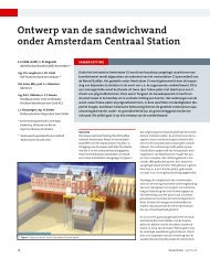
<strong>Design</strong> <strong>and</strong> <strong>validation</strong> <strong>of</strong> <strong>jet</strong> <strong>grouting</strong><br />
<strong>for</strong> <strong>the</strong> Amsterdam Central Station<br />
O.S. Langhorst, B.J. Schat,<br />
VOF Stationseil<strong>and</strong> Amsterdam, Movares<br />
Nederl<strong>and</strong> B.V. <strong>and</strong> Arcadis Infra B.V.<br />
J.C.W.M. de Wit, P.J. Bogaards,<br />
Adviesbureau Noord/Zuidlijn Amsterdam/<br />
Royal Haskoning<br />
R.D. Essler, J. Maertens,<br />
Consultants<br />
B.K.J. Obladen, C.F. Bosma,<br />
Principal Contractor, CSO, Combinatie<br />
Strukton Betonbouw van Oord ACZ<br />
ABSTRACT<br />
Beneath <strong>the</strong> Amsterdam Central Station is an excavation created within so-called ‘s<strong>and</strong>wich<br />
walls’ to be able to immerse a tunnel. The s<strong>and</strong>wich wall is a composite wall consisting<br />
<strong>of</strong> two rows <strong>of</strong> steel piles with a body <strong>of</strong> <strong>jet</strong> grout columns in between.<br />
In order to establish whe<strong>the</strong>r <strong>the</strong> requirements could be achieved a number <strong>of</strong> trials<br />
were carried out in advance <strong>of</strong> <strong>the</strong> main <strong>jet</strong> <strong>grouting</strong> to ensure that risk <strong>of</strong> gaps in<br />
<strong>the</strong> wall or inadequate strength were avoided. Significant advances have been made<br />
in improving <strong>the</strong> quality control <strong>of</strong> <strong>the</strong> <strong>jet</strong> grout process. The use <strong>of</strong> column callipers,<br />
hydrophones <strong>and</strong> spoil density measurements gave confidence to <strong>the</strong> actual diameter<br />
<strong>of</strong> <strong>jet</strong> grout column produced.<br />
J.J. Sleuwaegen, H. Dekker,<br />
Jet <strong>grouting</strong> Subcontractor, <strong>Smet</strong> <strong>Keller</strong><br />
Introduction<br />
Beneath <strong>the</strong> Amsterdam Central Station is an<br />
excavation created <strong>of</strong> <strong>the</strong> North/South Line,<br />
within a tunnel is immersed. This is characterised<br />
by <strong>the</strong> application <strong>of</strong> a particular technology<br />
in <strong>the</strong> <strong>for</strong>m <strong>of</strong>, inter alia, <strong>the</strong> so-called<br />
‘s<strong>and</strong>wich wall’. This is a composite wall consisting<br />
<strong>of</strong> two rows <strong>of</strong> steel piles with a body <strong>of</strong> <strong>jet</strong><br />
grout columns in between. This wall acts both<br />
as an excavation support wall <strong>and</strong> also provides<br />
vertical bearing. The installation <strong>of</strong> <strong>the</strong><br />
wall, within <strong>the</strong>se specific conditions (limited<br />
height, sensitive historical building, train station<br />
in service), within <strong>the</strong> design requirements<br />
set in terms <strong>of</strong> construction tolerance <strong>and</strong><br />
water <strong>and</strong> soil retention, may be regarded as<br />
being a pioneering achievement. Especially <strong>for</strong><br />
<strong>the</strong> <strong>jet</strong> <strong>grouting</strong> an integrated design <strong>and</strong> construction<br />
approach, including an extensive<br />
monitoring programme was needed.<br />
Work commenced on <strong>the</strong> s<strong>and</strong>wich wall in<br />
2003, when <strong>the</strong> wooden piles were extracted at<br />
<strong>the</strong> locations where <strong>the</strong> s<strong>and</strong>wich wall was to<br />
be constructed. In 2004, <strong>the</strong> steel piles <strong>for</strong> <strong>the</strong><br />
sou<strong>the</strong>rn wall sections were installed.<br />
From May 2005 to February 2006 <strong>for</strong> <strong>the</strong> sou<strong>the</strong>rn<br />
part <strong>of</strong> both walls <strong>jet</strong> <strong>grouting</strong> was carried<br />
out (2007/2008 <strong>the</strong> last nor<strong>the</strong>rn parts).<br />
This paper is <strong>the</strong> second part <strong>of</strong> two papers.<br />
The first paper deals with <strong>the</strong> design <strong>and</strong> construction<br />
philosophy <strong>of</strong> <strong>the</strong> work following <strong>the</strong><br />
observational method (Langhorst et al. 2007).<br />
This second paper will describe <strong>the</strong> <strong>validation</strong><br />
<strong>of</strong> <strong>the</strong> <strong>jet</strong> <strong>grouting</strong>. The requirements <strong>for</strong> <strong>the</strong> <strong>jet</strong><br />
<strong>grouting</strong> may be to achieve <strong>the</strong> design diameter<br />
within limits <strong>of</strong> ± 20% <strong>of</strong> <strong>the</strong> diameter, a<br />
positional tolerance within 1% <strong>of</strong> <strong>the</strong> design<br />
location at any point <strong>of</strong> each column, a minimum<br />
strength <strong>of</strong> 1.5 MPa. If <strong>the</strong> above requirements<br />
are achieved <strong>the</strong>n <strong>the</strong> risk <strong>of</strong> any leakage<br />
<strong>of</strong> water or soil through are minimised <strong>and</strong><br />
structural capacity is acceptable. In order to<br />
establish whe<strong>the</strong>r <strong>the</strong> above requirements<br />
could be achieved a number <strong>of</strong> trials were carried<br />
out in advance <strong>of</strong> <strong>the</strong> main <strong>jet</strong> <strong>grouting</strong> to<br />
ensure that risk <strong>of</strong> gaps in <strong>the</strong> wall or inadequate<br />
strength were avoided. Following completion<br />
<strong>of</strong> <strong>the</strong> trials, <strong>the</strong> main production <strong>jet</strong><br />
<strong>grouting</strong> commenced in May 2005 with<br />
ongoing quality control <strong>and</strong> <strong>validation</strong> using a<br />
number <strong>of</strong> techniques that are described below.<br />
Jet grout design layout<br />
The design <strong>of</strong> <strong>the</strong> s<strong>and</strong>wich wall consists <strong>of</strong><br />
two rows <strong>of</strong> steel Tubex piles <strong>of</strong> diameter<br />
around 450 mm surrounded by <strong>jet</strong> grout material.<br />
The column layout consists generically <strong>of</strong><br />
800-1,000 mm diameter single system<br />
columns <strong>for</strong>med between <strong>the</strong> Tubex piles <strong>and</strong><br />
2,000-2,200 mm diameter double system<br />
columns to infill <strong>the</strong> gaps between <strong>the</strong> two<br />
rows <strong>of</strong> piles <strong>and</strong> <strong>jet</strong> grout perimeter columns.<br />
The <strong>jet</strong> grout columns were <strong>jet</strong>ted full height<br />
from a depth <strong>of</strong> around 29 m (NAP –28 m) to<br />
within 1 m <strong>of</strong> ground level. Figure 1 shows <strong>the</strong><br />
schematic arrangement <strong>of</strong> <strong>the</strong> wall in plan. The<br />
two lines <strong>of</strong> Tubex piles are around 2.5 m apart<br />
<strong>and</strong> spaced at around 1 m centres.<br />
Difficulties associated with <strong>the</strong> achievement <strong>of</strong><br />
<strong>the</strong> design were <strong>the</strong> achievement <strong>of</strong> <strong>the</strong> positional<br />
tolerances <strong>and</strong> also <strong>the</strong> design diameters.<br />
In addition to <strong>the</strong>se problems, a number <strong>of</strong> relic<br />
wooden piles remained within <strong>the</strong> footprint <strong>of</strong><br />
<strong>the</strong> s<strong>and</strong>wich wall which would also complicate<br />
<strong>and</strong> potentially compromise quality. Because<br />
<strong>of</strong> <strong>the</strong> historical importance <strong>of</strong> <strong>the</strong> Central Station<br />
building <strong>and</strong> <strong>the</strong> construction programme,<br />
it was absolutely vital that <strong>the</strong> s<strong>and</strong>wich wall<br />
functioned correctly without causing unacceptable<br />
movements or distortion to <strong>the</strong> building.<br />
It was <strong>the</strong>re<strong>for</strong>e considered paramount that <strong>the</strong><br />
quality <strong>of</strong> <strong>the</strong> wall could be validated during<br />
<strong>the</strong> works to provide sufficient confidence <strong>for</strong><br />
<strong>the</strong> following excavation.<br />
Trial works<br />
The first trial was executed between February<br />
<strong>and</strong> April 2004 <strong>and</strong> consisted <strong>of</strong> a total <strong>of</strong> 6 single<br />
<strong>and</strong> 5 double system columns to investigate<br />
<strong>the</strong> two generic types <strong>of</strong> column (perimeter<br />
<strong>and</strong> infill) that were to be used on <strong>the</strong> project.<br />
18<br />
Geotechniek ECSMGE
<strong>Design</strong> <strong>and</strong> <strong>validation</strong> <strong>of</strong> <strong>jet</strong><strong>grouting</strong> <strong>for</strong> <strong>the</strong> Amsterdam Central Station<br />
\ Figure 1 Schematic layout <strong>of</strong> <strong>the</strong> wall<br />
The columns were <strong>jet</strong>ted to a level <strong>of</strong> NAP –28<br />
m, approximately 29 m below ground level.<br />
The results <strong>of</strong> <strong>the</strong> trial suggested that <strong>the</strong>re<br />
was some scatter in diameter <strong>and</strong> that <strong>the</strong><br />
required strength might be difficult to achieve.<br />
The main philosophy <strong>of</strong> this trial was to carry<br />
out <strong>the</strong> <strong>jet</strong> <strong>grouting</strong> with both a pre-cut or prewashing<br />
phase followed by a fur<strong>the</strong>r <strong>jet</strong> grout<br />
phase. The initial pre-cut phase was to <strong>the</strong>oretically<br />
enlarge <strong>the</strong> hole to around a diameter <strong>of</strong><br />
40 cm <strong>and</strong> thus allow <strong>for</strong> improved spoil return<br />
<strong>and</strong> less material to be cut with <strong>the</strong> follow on<br />
<strong>jet</strong> grout phase. The measurements <strong>of</strong> diameter<br />
by both column callipers <strong>and</strong> <strong>the</strong> hydrophones<br />
gave some confidence that <strong>the</strong> required diameter<br />
had been achieved but strength was on <strong>the</strong><br />
low side. Following this trial <strong>the</strong> design <strong>of</strong> <strong>the</strong><br />
s<strong>and</strong>wich wall was re-evaluated <strong>and</strong> a lower<br />
design strength resulted. This assisted <strong>the</strong> <strong>jet</strong><br />
grout process but ultimately it was decided by<br />
<strong>the</strong> steering group that <strong>the</strong> most satisfactory<br />
solution could be obtained by carrying out a<br />
pre-cut with significantly higher energy to<br />
actually construct <strong>the</strong> column diameter with<br />
this phase. The <strong>jet</strong> grout phase was <strong>the</strong>n used<br />
to create a high cement content by <strong>the</strong> injection<br />
<strong>of</strong> a low water cement ratio grout. This methodology<br />
has <strong>the</strong> benefit that lower pump power<br />
is required <strong>for</strong> <strong>the</strong> pre-cut phase to achieve <strong>the</strong><br />
high pressures <strong>and</strong> flows required <strong>and</strong> that <strong>the</strong><br />
heavy <strong>jet</strong> grout grout injected was more liable<br />
to displace <strong>the</strong> lighter pre-cut spoil <strong>and</strong> give an<br />
enhanced strength through displacement<br />
ra<strong>the</strong>r than mixing. Following this change in<br />
methodology it was concluded that a fur<strong>the</strong>r<br />
small scale trial was required to validate <strong>the</strong><br />
new approach <strong>and</strong> in May 2005, five fur<strong>the</strong>r<br />
columns were constructed using <strong>the</strong> higher<br />
energy pre-cut with grouts <strong>of</strong> differing density.<br />
The column calliper, spoil density <strong>and</strong> hydro-<br />
phones were used again to validate diameters<br />
achieved. The results <strong>of</strong> this trial indicated that<br />
<strong>the</strong> high energy pre-cut was successful but that<br />
a lower water cement ratio grout was needed to<br />
ensure that <strong>the</strong> clay material was lifted out <strong>of</strong><br />
<strong>the</strong> columns.<br />
Column production<br />
The steering group considered that <strong>the</strong> production<br />
<strong>of</strong> each column needed very careful quality<br />
control <strong>and</strong> <strong>validation</strong> to ensure that <strong>the</strong><br />
integrity <strong>of</strong> <strong>the</strong> s<strong>and</strong>wich wall would not be<br />
compromised. It was <strong>the</strong>re<strong>for</strong>e agreed that <strong>the</strong><br />
following general sequence would be adopted.<br />
Drilling<br />
The drilling <strong>of</strong> each column was regulated to a<br />
maximum rate <strong>of</strong> penetration as it had been<br />
demonstrated during <strong>the</strong> previous trials that<br />
increasing rate <strong>of</strong> penetration gave more deviation.<br />
Following completion <strong>of</strong> drilling, <strong>the</strong> hole<br />
\ Figure 2 Typical schematic sequence <strong>for</strong> a column<br />
was surveyed by introducing an inclinometer<br />
probe down <strong>the</strong> central annulus <strong>of</strong> <strong>the</strong> <strong>jet</strong> grout<br />
rods. This survey was repeated a number <strong>of</strong><br />
times with a different probe orientation to give<br />
<strong>the</strong> maximum confidence on hole position.<br />
Using this survey data, <strong>the</strong> as built drill hole<br />
position was plotted on a digital layout drawing<br />
<strong>and</strong> an assessment made as to whe<strong>the</strong>r<br />
<strong>the</strong> column could be <strong>jet</strong>ted as normal, <strong>the</strong> parameters<br />
adjusted to make a slightly larger<br />
column, only a partial depth <strong>jet</strong>ted <strong>and</strong> <strong>the</strong><br />
outst<strong>and</strong>ing section re<strong>jet</strong>ted at a later date,<br />
ab<strong>and</strong>oned, grouted up <strong>and</strong> redrilled at a later<br />
date. This initial quality control ensured that<br />
columns were only <strong>jet</strong>ted when <strong>the</strong> column<br />
was positioned within its design tolerance <strong>and</strong><br />
simplified later column production.<br />
Column Sequence<br />
Because <strong>of</strong> <strong>the</strong> length (around 28 m) <strong>of</strong> each<br />
column <strong>and</strong> <strong>the</strong> necessity to pre-cut <strong>and</strong> <strong>the</strong>n<br />
<strong>jet</strong> grout, it was considered that <strong>the</strong> column<br />
had to be pre-cut in three sections. This was to<br />
ensure that <strong>the</strong> time between <strong>the</strong> start <strong>of</strong> precut<br />
<strong>and</strong> <strong>the</strong> start <strong>of</strong> <strong>jet</strong> grout was kept to a sensible<br />
limit which would allow <strong>the</strong> <strong>jet</strong> <strong>grouting</strong><br />
to be carried out without <strong>the</strong> risk <strong>of</strong> excessive<br />
sedimentation or initial grout set. Measurements<br />
<strong>of</strong> diameter were also carried out following<br />
pre-cut <strong>and</strong> this sequence assisted with<br />
maintaining free access to <strong>the</strong> bottom <strong>of</strong> <strong>the</strong><br />
column <strong>for</strong> <strong>the</strong> calliper device. Because <strong>the</strong>re<br />
were a number <strong>of</strong> differing parameters in use,<br />
control <strong>of</strong> sequence was very important <strong>and</strong><br />
within some sequences, parameters would be<br />
changed depending on soil type or density, see<br />
figure 2.<br />
Column Jetting Parameters<br />
The <strong>jet</strong> grout parameters <strong>for</strong> each type <strong>and</strong> diameter<br />
<strong>of</strong> column were established from <strong>the</strong><br />
previous trial works <strong>and</strong> also updated as <strong>the</strong><br />
works proceeded. The use <strong>of</strong> hydrophones <strong>and</strong><br />
<strong>the</strong> column callipers allowed a high degree <strong>of</strong><br />
confidence <strong>of</strong> <strong>the</strong> diameter achieved <strong>and</strong> <strong>the</strong><br />
reliability <strong>of</strong> <strong>the</strong> <strong>jet</strong>ting parameters in use.<br />
With <strong>the</strong> hydrophones it was also possible to<br />
adjust <strong>the</strong> parameters in real time if <strong>the</strong> feedback<br />
from <strong>the</strong> testing during <strong>jet</strong>ting was unfavourable<br />
(this is discussed in more detail<br />
below). Figure 3 gives an example <strong>of</strong> <strong>the</strong> parameters<br />
used <strong>for</strong> a 1,000 mm single system<br />
column.<br />
Column diameter measurement<br />
One <strong>of</strong> <strong>the</strong> most difficult aspects <strong>of</strong> <strong>jet</strong> <strong>grouting</strong><br />
in <strong>the</strong> past has been <strong>the</strong> verification <strong>of</strong> column<br />
Geotechniek ECSMGE<br />
19
<strong>Design</strong> <strong>and</strong> <strong>validation</strong> <strong>of</strong> <strong>jet</strong><strong>grouting</strong> <strong>for</strong> <strong>the</strong> Amsterdam Central Station<br />
\ Figure 3 Typical <strong>jet</strong> <strong>grouting</strong> parameters 1,000 mm column<br />
\ Figure 4 Schematic section <strong>of</strong> column calliper<br />
\ Figure 5 Diameter measurement plot<br />
diameter as this has <strong>of</strong>ten lead to design problems<br />
when insufficient diameter has been<br />
<strong>for</strong>med. Three methods have been developed<br />
on <strong>the</strong> Central Station project which is discussed<br />
below.<br />
Column Calliper System<br />
The contractor provided a hydraulically activated<br />
column calliper <strong>for</strong> use on <strong>the</strong> project.<br />
A schematic illustration <strong>of</strong> <strong>the</strong> device is given<br />
as figure 4. Considerable work was required,<br />
prior to <strong>the</strong> start <strong>of</strong>, <strong>and</strong> during construction to<br />
enable a more accurate interpretation <strong>of</strong> <strong>the</strong><br />
results.<br />
Figure 5 shows a typical result <strong>of</strong> a diameter<br />
measurement. The calliper operates by applying<br />
a pressure to a hydraulic cylinder which<br />
exp<strong>and</strong>s <strong>the</strong> arms as shown on figure 4.<br />
The displaced volume <strong>and</strong> pressure <strong>of</strong> <strong>the</strong><br />
cylinder are measured at <strong>the</strong> surface. Be<strong>for</strong>e an<br />
actual measurement is carried out, a calibration<br />
<strong>of</strong> <strong>the</strong> device is required. This is carried out<br />
by extending <strong>the</strong> arms <strong>and</strong> measuring <strong>the</strong><br />
resulting pressure <strong>and</strong> volume change within<br />
<strong>the</strong> system. On figure 5, curve A is <strong>the</strong> calibration<br />
<strong>of</strong> diameter against displaced volume <strong>and</strong><br />
curve B is <strong>the</strong> calibration <strong>of</strong> applied pressure<br />
against displaced volume. To interpret <strong>the</strong><br />
actual column measurement <strong>the</strong> applied pressure<br />
is plotted against displaced cylinder volume<br />
(curve C). Because <strong>the</strong> behaviour is slightly<br />
different in <strong>the</strong> ground <strong>the</strong> device does not follow<br />
<strong>the</strong> calibration line <strong>and</strong> <strong>the</strong> final portion <strong>of</strong><br />
curve C is projected back to curve B. The intersection<br />
with curve B <strong>the</strong>n defines <strong>the</strong> volume<br />
at which point <strong>the</strong> arms touch <strong>the</strong> sides <strong>of</strong> <strong>the</strong><br />
column <strong>and</strong> <strong>the</strong>n <strong>the</strong> diameter can be estimated<br />
from curve A as shown. A fur<strong>the</strong>r correction<br />
(not shown) is required <strong>for</strong> <strong>the</strong> expansion<br />
<strong>of</strong> <strong>the</strong> hydraulic hoses under pressure but<br />
surface calibrations with <strong>the</strong> arms placed<br />
between concrete <strong>and</strong> clay blocks proved that<br />
<strong>the</strong> measurements are repeatable <strong>and</strong> accurate.<br />
In a final development, digital inclinometers<br />
were added to <strong>the</strong> arms which gave a better<br />
clarity in <strong>the</strong> measurements. It is considered<br />
that this device gives good indication <strong>of</strong> actual<br />
column diameter <strong>and</strong> is an important advance<br />
<strong>for</strong> <strong>the</strong> <strong>jet</strong> <strong>grouting</strong> industry.<br />
Hydrophone System<br />
In addition to <strong>the</strong> use <strong>of</strong> <strong>the</strong> column calliper, a<br />
hydrophone system was also deployed. Figure 6<br />
shows <strong>the</strong> schematic diagram <strong>of</strong> <strong>the</strong> operation<br />
<strong>of</strong> hydrophones.<br />
In operation a number <strong>of</strong> small diameter holes<br />
are drilled around <strong>the</strong> periphery <strong>of</strong> <strong>the</strong> column<br />
to be tested. These can be 50-75 mm in diameter.<br />
During <strong>the</strong> <strong>jet</strong> <strong>grouting</strong> process, microphones<br />
placed at a depth close to <strong>the</strong> level <strong>of</strong> <strong>the</strong> <strong>jet</strong><br />
grout nozzle(s) are used to measure <strong>the</strong> noise<br />
resulting from <strong>the</strong> impact <strong>of</strong> <strong>the</strong> <strong>jet</strong> on <strong>the</strong><br />
hydrophone tubes. Placing <strong>the</strong> tubes at differing<br />
distances from <strong>the</strong> centre <strong>of</strong> <strong>the</strong> column<br />
allows an estimate <strong>of</strong> <strong>the</strong> diameter range<br />
depending on <strong>the</strong> response <strong>of</strong> <strong>the</strong> system.<br />
Fur<strong>the</strong>rmore, <strong>the</strong> hollow Tubex piles were also<br />
used to carry out hydrophone measurements<br />
during <strong>the</strong> <strong>jet</strong> <strong>grouting</strong> works. Here, <strong>the</strong> main<br />
purpose was to verify that closure between <strong>the</strong><br />
perimeter column <strong>and</strong> steel pile was achieved.<br />
Figure 7 shows <strong>the</strong> resulting display used<br />
during <strong>jet</strong> <strong>grouting</strong>. The amplitude <strong>of</strong> <strong>the</strong><br />
20<br />
Geotechniek ECSMGE
<strong>Design</strong> <strong>and</strong> <strong>validation</strong> <strong>of</strong> <strong>jet</strong><strong>grouting</strong> <strong>for</strong> <strong>the</strong> Amsterdam Central Station<br />
\ Figure 6 Principle <strong>of</strong> hydrophone measurement<br />
waves matches <strong>the</strong> passage <strong>of</strong> <strong>the</strong> <strong>jet</strong> <strong>and</strong> thus<br />
<strong>the</strong> diameter can be proved. It is also possible to<br />
adjust <strong>the</strong> <strong>jet</strong> <strong>grouting</strong> parameters if <strong>the</strong> results<br />
<strong>of</strong> <strong>the</strong> hydrophones are not conclusive thus <strong>for</strong><br />
example <strong>the</strong> lift speed can be reduced or<br />
increased <strong>and</strong> <strong>the</strong> response on <strong>the</strong> hydrophones<br />
noted. It is <strong>the</strong>re<strong>for</strong>e possible to match <strong>the</strong> <strong>jet</strong><br />
<strong>grouting</strong> parameters to <strong>the</strong> required diameters<br />
more efficiently.<br />
Spoil Density Measurements<br />
In addition to <strong>the</strong> use <strong>of</strong> <strong>the</strong> column calliper<br />
<strong>and</strong> <strong>the</strong> hydrophones, <strong>the</strong> density <strong>of</strong> <strong>the</strong> spoil<br />
returns from <strong>the</strong> borehole was measured at 1 m<br />
intervals during pre-cut <strong>and</strong> <strong>jet</strong> <strong>grouting</strong>.<br />
In principle this is a very low cost option <strong>for</strong><br />
diameter measurement as it does not delay <strong>the</strong><br />
operation <strong>and</strong> is simple to carry out. At Central<br />
Station a number <strong>of</strong> methods were investigated<br />
including hydrometers <strong>and</strong> mud balances.<br />
The interpretation <strong>of</strong> <strong>the</strong>se was found to be difficult<br />
if <strong>the</strong> highest accuracy was required <strong>and</strong><br />
finally a sample was measured by filling a<br />
\ Figure 8 Results <strong>of</strong> a diameter measurement<br />
\ Figure 7 Hydrophone measurement display<br />
1 litre container <strong>and</strong> using a digital balance to<br />
weigh it. At a later stage a 1 litre container<br />
with a close fitting lid was manufactured to<br />
give more repeatability <strong>of</strong> volume. The <strong>the</strong>ory<br />
<strong>of</strong> relating spoil return density to column diameter<br />
has been reported in a number <strong>of</strong> papers<br />
(Kauschinger et al. 1992) <strong>and</strong> (Croce & Flora<br />
2000). Essentially a mass balance approach is<br />
adopted to <strong>the</strong> material within <strong>the</strong> <strong>jet</strong> grout<br />
body <strong>and</strong> <strong>the</strong> excess material ejected from <strong>the</strong><br />
borehole. Assumptions are made that ei<strong>the</strong>r<br />
<strong>the</strong> column composition is identical to <strong>the</strong> spoil<br />
ejected or that certain percentages <strong>of</strong> <strong>the</strong> original<br />
material are retained within <strong>the</strong> column.<br />
Usually <strong>for</strong> s<strong>and</strong>s <strong>the</strong> first relationship is used<br />
but as larger particles or clay are present <strong>the</strong>n<br />
<strong>the</strong> mass balance approach becomes more complex.<br />
Figure 8 shows <strong>the</strong> results <strong>of</strong> a measurement<br />
by both spoil density <strong>and</strong> column callipers<br />
<strong>for</strong> a column. Because <strong>of</strong> <strong>the</strong> overlap <strong>of</strong> <strong>the</strong><br />
column with previously constructed columns,<br />
<strong>the</strong> calculation <strong>of</strong> spoil density is more complicated<br />
as an assessment <strong>of</strong> <strong>the</strong> actual column<br />
volume being cut is required. For <strong>the</strong> perimeter<br />
columns <strong>the</strong> areal percentage cut was around<br />
80-85 % whereas <strong>for</strong> <strong>the</strong> infill columns this<br />
ranged from 40-55 %. This change in column<br />
volume has a pr<strong>of</strong>ound effect on calculation <strong>of</strong><br />
spoil density or conversely back calculation <strong>of</strong><br />
diameter <strong>and</strong> if a truly accurate solution is<br />
required <strong>the</strong>n an iteration between adjustment<br />
<strong>of</strong> areal percentage <strong>and</strong> predicted diameter is<br />
required. However <strong>the</strong> results can give an indication<br />
<strong>of</strong> column diameter to within 20 %.<br />
Conclusions<br />
Significant advances have been made in<br />
Amsterdam in improving <strong>the</strong> quality control <strong>of</strong><br />
<strong>the</strong> <strong>jet</strong> grout process. The use <strong>of</strong> column callipers,<br />
hydrophones <strong>and</strong> spoil density measurements<br />
all give confidence to <strong>the</strong> actual diameter<br />
<strong>of</strong> <strong>jet</strong> grout column produced <strong>and</strong> it is<br />
expected that with fur<strong>the</strong>r development in all<br />
three techniques a better accuracy can be<br />
obtained. The use <strong>of</strong> a two stage process <strong>of</strong> a<br />
pre-cut <strong>and</strong> <strong>jet</strong> grout phase allows <strong>the</strong> separation<br />
<strong>of</strong> column diameter creation <strong>and</strong> column<br />
strength. It is considered that this approach<br />
will allow <strong>the</strong> use <strong>of</strong> higher design strengths in<br />
clays than was previously considered.<br />
References<br />
[1] Wit, J.C.M. de, Bogaards, P.J., Langhorst, O.S.,<br />
Schat, B.J., Essler, R.D., Maertens, J., Obladen,<br />
B.K.J., Bosma, C.F., Sleuwaegen, J.J., <strong>and</strong> Dekker,<br />
J. (2007), <strong>Design</strong> <strong>and</strong> construction <strong>of</strong> a<br />
metro station in Amsterdam, challenging<br />
<strong>the</strong> limits <strong>of</strong> <strong>jet</strong> <strong>grouting</strong>. Proc. 14 th Eur. Conf.<br />
on Soil Mech. <strong>and</strong> Geot. Eng. 24-27 September<br />
2007, Madrid, to be published<br />
[2] Kauschinger, Hankour, <strong>and</strong> Perry (1992 )<br />
Methods to estimate Composition <strong>of</strong> Jet<br />
Grout Bodies. Proc. ASCE Conference Grouting,<br />
Soil Improvement <strong>and</strong> Geosyn<strong>the</strong>tics,<br />
New Orleans<br />
Geotechniek ECSMGE<br />
21