Long-Period Fiber Gratings as Band-Rejection Filters
Long-Period Fiber Gratings as Band-Rejection Filters
Long-Period Fiber Gratings as Band-Rejection Filters

You also want an ePaper? Increase the reach of your titles
YUMPU automatically turns print PDFs into web optimized ePapers that Google loves.
Properties<br />
In Figure 6, we show the transmission spectrum of a strong<br />
grating of length 2.54 cm written with a grating period<br />
= 402 μm. The maximum loss is 32 dB at a peak wavelength<br />
λ p = 1517 nm, the 20 dB isolation point is<br />
4 nm wide, the 3 dB point (λ) is 22 nm, and the<br />
insertion loss is < 0.20 dB for wavelengths < 1480<br />
nm and > 1545 nm. Viewed over a broader wavelength<br />
range, a typical spectrum is shown in Figure<br />
7 (for a FLEXCOR fiber with = 198 μm) which<br />
clearly indicates the different cladding modes.<br />
Several different gratings with periodicities in the<br />
150–600 μm range were fabricated and the different<br />
peaks in the spectrum were categorized according to<br />
the different cladding mode orders. The experimental<br />
results of the complete DSF characterization are<br />
shown in Figure 8. One of the key features that distinguishes<br />
the long-period gratings from their shortperiod<br />
blazed counterparts is the ultra-low backreflection<br />
properties. An optical coherence domain<br />
reflectometer trace for a long-period grating is<br />
shown in Figure 9. The backreflection numbers<br />
are consistent with our estimate (b<strong>as</strong>ed on detailed<br />
growth and annealing experiments) of maximum<br />
UV-induced n of 5 × 10 −4 . A me<strong>as</strong>urement of<br />
polarization properties of these devices shows the<br />
polarization mode dispersion (PMD) < 0.01 ps and<br />
polarization dependent loss (PDL) < 0.02 dB.<br />
Applications<br />
The most common use of the long-period gratings is<br />
<strong>as</strong> a band-rejection filter and several applications<br />
have been explored. The grating of Figure 6 can be<br />
used <strong>as</strong> an ASE suppressor, presenting a near-transparent<br />
path to the pump (1480 nm) and signal<br />
wavelengths (> 1545 nm) in erbium-doped amplifiers.<br />
A band-rejection filter is also used to remove<br />
unnecessary Stokes’ orders in a c<strong>as</strong>caded Raman<br />
amplifier/l<strong>as</strong>er [18]. For example, the grating of<br />
Figure 10 is used to reject extraneous 1310 nm light<br />
while simultaneously allowing the 1240 nm pump<br />
wavelength to be transmitted with minimum loss.<br />
The band-gap filling effect [19] seen in Bragg-grating<br />
stabilized 980 nm pump-diodes can also be<br />
countered using a small band-rejection filter at<br />
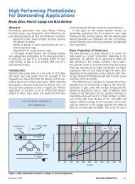
∼ 1 μm. This effect is shown in<br />
Figure 11, where the tendency of the l<strong>as</strong>er to split its<br />
spectrum and l<strong>as</strong>e at λ >980 nm (thus rendering it<br />
ineffective for erbium pumping applications) is<br />
curbed by the addition of the filter whose transmission<br />
spectrum is shown in the inset [20]. In coarse<br />
WDM applications, it is often critical to insert a<br />
cleanup filter after the demultiplexer (at the receiver<br />
end) to remove vestiges of the channel that is not<br />
being monitored. For a 1310/1550 nm system, we<br />
can fabricate this filter by splicing two gratings separated<br />
by a few nanometers in peak wavelength.<br />
Output Power (dBm)<br />
Output Power (dBm)<br />
−30<br />
−40<br />
−50<br />
−60<br />
−70<br />
With concatenation, we have fabricated devices with a 15 dB<br />
bandwidth of 20 nm, a 20 dB bandwidth of 10 nm<br />
(centered around 1555 nm), with an insertion loss < 0.20 dB<br />
at 1310 nm.<br />
−80<br />
950 975 1000 1025<br />
−35<br />
−45<br />
−55<br />
−65<br />
Wavelength(nm)<br />
Figure 11: Effect of band-rejection filters on grating-stabilized<br />
980 nm pump diodes. (a) Bragg-grating stabilized semiconductor pump diode<br />
shows a split in the spectrum. (b) The addition of a long-period grating moves<br />
the peak l<strong>as</strong>ing wavelength toward 980 nm. Inset shows transmission spectrum<br />
of long-period grating [20].<br />
June 2007 IEEE LEOS NEWSLETTER 17<br />
Transmission (dB)<br />
(a)<br />
0<br />
−1<br />
−2<br />
−3<br />
−4<br />
−5<br />
950 975 1000 1025 1050<br />
Wavelength (nm)<br />
−75<br />
950 975 1000 1025<br />
Wavelength(nm)<br />
(b)