Long-Period Fiber Gratings as Band-Rejection Filters
Long-Period Fiber Gratings as Band-Rejection Filters
Long-Period Fiber Gratings as Band-Rejection Filters

Create successful ePaper yourself
Turn your PDF publications into a flip-book with our unique Google optimized e-Paper software.
Special 30th Anniversary<br />
<strong>Long</strong>-<strong>Period</strong> <strong>Fiber</strong> <strong>Gratings</strong> <strong>as</strong> <strong>Band</strong>-<strong>Rejection</strong> <strong>Filters</strong><br />
Ashish M. Vengsarkar, Paul J. Lemaire, Justin B. Judkins, Vikram Bhatia,<br />
Turan Erdogan, and John E. Sipe<br />
Reprint of most cited article from Journal of Lightwave Technology - Vol. 14, No. 1, pp 58-65<br />
ω = ω 1<br />
ω = ω 2 , ω 2 < ω 1<br />
Short-<strong>Period</strong> Grating<br />
2π/A<br />
−β 01 0 β (2) β (1) n cl<br />
ω β 01<br />
C<br />
2π/A<br />
−β 01 0 β (2) β (1) β 01<br />
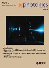
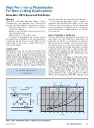
Figure 1: Ph<strong>as</strong>e matching considerations for short- and longperiod<br />
gratings.<br />
Wavelength (nm)<br />
1600<br />
1500<br />
1400<br />
1300<br />
1200<br />
1100<br />
1000<br />
900<br />
150 200 250 300 350 400 450 500 550 600<br />
Grating <strong>Period</strong> (μm)<br />
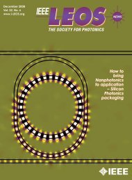
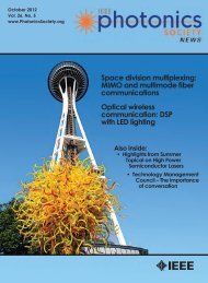
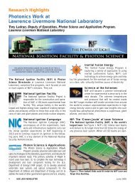
Figure 2: Theoretical determination of the relationship between<br />
grating periodicity and wavelengths where guided-to-cladding<br />
mode coupling takes place for an AT&T dispersion shifted fiber.<br />
MANUSCRIPT RECEIVED APRIL 21, 1995; REVISED MAY 30, 1995.<br />
A.M. VENGSARKAR AND P.J. LEMAIRE ARE WITH AT&T BELL<br />
LABORATORIES, MURRAY HILL, NJ 07974 USA.<br />
J.B. JUDKINS WAS WITH THE DEPARTMENT OF ELECTRICAL<br />
ENGINEERING, UNIVERSITY OF ARIZONA, TUCSON, AZ 85723 USA. HE<br />
IS NOW WITH AT&T BELL LABORATORIES, MURRAY HILL, NJ 07974 USA.<br />
V. BHATIA IS WITH THE BRADLEY DEPARTMENT OF ELECTRICAL<br />
ENGINEERING, VIRGINIA TECH, BLACKSBURG, VA 24061 USA.<br />
T. ERDOGAN IS WITH THE INSTITUTE OF OPTICS, UNIVERSITY OF<br />
ROCHESTER, ROCHESTER, NY 14627 USA.<br />
J.E. SIPE IS WITH THE DEPARTMENT OF PHYSICS, UNIVERSITY OF<br />
TORONTO, ONT. M5S 1A7, CANADA.<br />
PUBLISHER ITEM IDENTIFIER: S 0733-8724(96)00701-3.<br />
Abstract<br />
We present a new cl<strong>as</strong>s of long-period fiber gratings that can be<br />
used <strong>as</strong> in-flber, low-loss, band-rejection filters. Photoinduced<br />
periodic structures written in the core of standard communication-grade<br />
fibers couple light from the fundamental guided<br />
mode to forward propagating cladding modes and act <strong>as</strong> spectrally<br />
selective loss elements with insertion losses < 0.2 dB,<br />
backreflections < −80 dB, polarization-mode-dispersions <<br />
0.01 ps and polarization-dependent-losses < 0.02 dB.<br />
Introduction<br />
Optical fiber communications systems that use optical amplifiers<br />
are incre<strong>as</strong>ingly seeking high-performance devices that<br />
function <strong>as</strong> spectrally selective filters. For example, ASE filters<br />
that improve noise figure in erbium doped fiber amplifiers and<br />
band-rejection filters used to remove unnecessary Stokes’<br />
orders in c<strong>as</strong>caded Raman amplifiers should have low insertion<br />
losses and low back-reflections. In addition, they must be relatively<br />
inexpensive to m<strong>as</strong>s-produce and should be compact<br />
after packaging. While bulk-optic filters and short-period<br />
Bragg gratings [1] can be used for some of the applications, all<br />
the aforementioned requirements are rarely met. In this paper,<br />
we present photoinduced, long-period fiber gratings that can<br />
be used <strong>as</strong> low-loss, in-fiber band-rejection filters.<br />
The fabrication principle is b<strong>as</strong>ed on the ability to induce<br />
large index changes in hydrogen loaded germanosilicate fibers<br />
by exposing the cores to ultraviolet (UV) light, typically, in the<br />
242–248 nm range [2]. This technology h<strong>as</strong> been successfully<br />
used for making Bragg-type fiber gratings [3] (periodicities<br />
less than a micron) that are incre<strong>as</strong>ingly being used <strong>as</strong> reflectors<br />
and in the fabrication of high-efficiency fiber l<strong>as</strong>ers [4], [5].<br />
<strong>Long</strong>-period fiber gratings with periodicities in the hundreds<br />
of microns have been used in the p<strong>as</strong>t for coupling from one<br />
guided mode to another. For example, a blazed grating in a<br />
two-mode fiber h<strong>as</strong> been used to induce an LP 01 ↔ LP 11 mode<br />
conversion [6], LP 01 ↔ LP 02 mode converters have been<br />
demonstrated [7], and rocking filters have been written in single-mode<br />
fibers for polarization mode conversion [8], [9].<br />
In this paper, we describe periodic structures that couple the<br />
guided fundamental mode in a single-mode fiber to forwardpropagating<br />
cladding modes. These modes decay rapidly <strong>as</strong> they<br />
propagate along the fiber axis owing to scattering losses at the<br />
cladding-air interface and bends in the fiber. Since the coupling<br />
is wavelength-selective, the fiber grating acts <strong>as</strong> a wavelengthdependent<br />
loss element. In the subsequent sections, we describe<br />
the principle of operation of such gratings, develop a theory and<br />
present experimental results. We also evaluate their stability to<br />
strain, temperature, recoating, and bends.<br />
12 IEEE LEOS NEWSLETTER June 2007
Principle of Operation<br />
Consider a single-mode fiber with the propagation constant of<br />
the fundamental mode, LP 01 , denoted by β 01 and the propagation<br />
constants of the cladding modes given by β (n)<br />
cl , where<br />
the superscript denotes the order of the mode. The relative<br />
positions of the propagation constants (for a given<br />
ω, ω = ω 1 ) are shown in Figure 1. The hatched region<br />
extending from 0 to n cl ω/c represents the continuum of radiation<br />
modes that exist for an infinite cladding. We restrict this<br />
analysis to a purely rectangular index modulation along the<br />
fiber with the periodic index structure being perpendicular to<br />
the fiber axis. These <strong>as</strong>sumptions exclude blazed gratings and<br />
<strong>as</strong> a result modal overlap conditions dictate that the fundamental<br />
guided mode can couple only to those cladding modes<br />
that are azimuthally symmetric with a central peak at r = 0.<br />
The ordinals of β (n)<br />
cl reflect this <strong>as</strong>sumption.<br />
In order to couple from a forward propagating guided<br />
mode to backward propagating (guided or radiation) modes<br />
the ph<strong>as</strong>e matching K-vector is large, thus requiring a shortperiod<br />
grating. Examples of these gratings are Bragg-reflectors<br />
(for coupling to a back-propagating guided mode, denoted<br />
by −β 01 ) or blazed/tilted gratings (for coupling to backpropagating<br />
radiation modes).<br />
The ph<strong>as</strong>e matching condition between the guided mode<br />
and the forward propagating cladding modes is given by<br />
β 01 − β (n)<br />
cl<br />
= 2π <br />
(1)<br />
fiber at a specific wavelength. We then obtain a set of periodicities<br />
(n) that will meet the ph<strong>as</strong>e-matching condition given<br />
by (1). This step is then repeated for several different wavelengths;<br />
the resulting plot of coupling-wavelength versus<br />
grating-period is shown for an AT&T dispersion-shifted fiber<br />
(DSF) in Figure 2. One can choose a grating period such that<br />
mode coupling takes place at any desired wavelength. Further,<br />
the choice of ’s also allows the designer to vary the separation<br />
between two cladding modes, denoted by δλ.<br />
The AT&T DSF w<strong>as</strong> modeled by using an exact refractive<br />
index profile in the mode-parameter calculation program<br />
developed by Lenahan [10]. The method of solution<br />
involved a finite element approach that reduced Maxwell’s<br />
equations to standard eigenvalue equations and an eigensystem<br />
package (EISPACK) computed the desired propagation<br />
parameters for the guided mode. The cladding mode propagation<br />
constants were calculated using the eigenvalue equa-<br />
Broadband<br />
Source<br />
PC<br />
<strong>Fiber</strong><br />
KrF L<strong>as</strong>er<br />
<strong>Fiber</strong><br />
Optical<br />
Spectrum<br />
Analyzer<br />
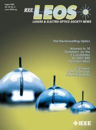
Figure 3: Experimental setup for long-period grating fabrication.<br />
AM: Amplitude m<strong>as</strong>k. PC: Polarization controller.<br />
AM<br />
where is the grating periodicity required to couple<br />
the fundamental mode to the nth-cladding mode. In<br />
this c<strong>as</strong>e, the ph<strong>as</strong>e matching vector is short resulting<br />
in a long , typically on the order of hundreds of<br />
microns. For another ω, (ω = ω 2 where ω 2 ω 1 ) one<br />
can visualize the K-vector of the grating coupling the<br />
guided mode to the edge of the radiation mode continuum.<br />
This optical frequency ω cut corresponds to a<br />
minimum wavelength, λ cut , at which the grating can<br />
couple the fundamental mode to the radiation<br />
modes. This parameter is used to describe grating<br />
behavior in the subsequent analysis.<br />
Theory<br />
One can now predict the wavelengths at which<br />
mode-coupling will be enabled by a particular grating<br />
period. The first step in our modeling approach<br />
involves the calculation of the propagation constants<br />
of the guided and the various cladding modes of a
0<br />
−4<br />
A<br />
B<br />
C<br />
0<br />
−5<br />
Transmission (dB)<br />
−8<br />
−12<br />
−16<br />
D<br />
Transmission (dB)<br />
−10<br />
−15<br />
−20<br />
−25<br />
−20<br />
1520 1540 1560 1580 1600 1620<br />
Wavelength (nm)<br />
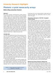
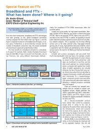
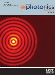
Figure 4: Growth of a long-period grating <strong>as</strong> a function of time. A:<br />
1 min, B: 2 min, C: 3 min, D: 4 min, E: 5 min.<br />
E<br />
−30<br />
−35<br />
1475 1492 1509 1526 1543 1560<br />
Wavelength (nm)<br />
Figure 6: Transmission spectrum of a band-rejection filter.<br />
1670<br />
0<br />
1640<br />
−5<br />
Peak Wavelength (nm)<br />
1610<br />
1580<br />
1550<br />
Transmission (dB)<br />
−10<br />
−15<br />
1520<br />
1490<br />
0 1 2 3 4<br />
Time (h)<br />
Figure 5: Effect of annealing (@ 150°C) on peak wavelengths of a<br />
long-period grating.<br />
tions [11] for a simple multimode step-index structure (of<br />
diameter 125 μm) ignoring the effect of the core. The<br />
curves in Figure 2, thus, are not accurate indicators of the<br />
exact wavelengths at which coupling occurs and are to be<br />
used merely <strong>as</strong> a guideline. They summarize the behavior of<br />
the grating peak wavelengths and separation and their<br />
dependence on different periodicities. For example, to<br />
obtain a δλ > 100 nm for a grating peaked at 1550 nm one<br />
would use a period of 200 μm, while for a δλ < 50 nm a<br />
grating period of 500 μm may be desirable. The curves are<br />
highly sensitive to small variations in effective indexes of<br />
the different modes. The wavelength difference δλ between<br />
the modes can also be calculated using a simplified approximation,<br />
<strong>as</strong> described below. The minimum wavelength,<br />
−20<br />
900 1000 1100 1200 1300 1400<br />
Wavelength (nm)<br />
Figure 7: Transmission spectrum over a broad wavelength range<br />
shows the various LP 0m cladding modes to which the fundamental<br />
guided mode couples.<br />
λ cut , at which guided-to-radiation mode coupling is possible<br />
(for an infinite cladding) w<strong>as</strong> calculated from the ph<strong>as</strong>ematching<br />
condition of (1) and the procedure outlined in<br />
[12] using an equivalent step-index model for the DSF. The<br />
result is given by the d<strong>as</strong>hed curve in Figure 2, which shows<br />
that for any given periodicity, λ cut is less than the wavelengths<br />
at which the cladding-mode coupling takes place.<br />
This observation is consistent with the ph<strong>as</strong>e-matching diagrams<br />
of Figure 1.<br />
Another method of calculating the wavelength separation<br />
between the different cladding modes makes use of the wavelength<br />
λ cut . We consider the transverse component of the<br />
propagation constant of the cladding mode κ. This component<br />
satisfies the condition<br />
14 IEEE LEOS NEWSLETTER June 2007
βcl 2 + κ2 = ω2 n 2 cl<br />
(2)<br />
c 2<br />
where n cl is the refractive index of the cladding. Assuming a<br />
simple step-index profile, the axially symmetric cladding<br />
modes that are nonzero at the origin are described by Bessel<br />
function of order zero, namely, J 0 (κ a cl ) where a cl is the<br />
cladding radius. The difference in the wavelengths at which<br />
the guided mode couples to the different cladding modes, δλ,<br />
correspond to the separation of the zeros of the Bessel function<br />
[13]. Since the difference in the zeroes of J 0 (x), denoted by<br />
δx 0 , can be approximated by δx 0 ≈ π [14], the δλ’s will correspond<br />
to the condition κ a cl = πp where p is an integer. The<br />
expression for δλ is obtained in an indirect manner, <strong>as</strong> follows.<br />
We first find the separation in wavelength between the<br />
pth-cladding mode and λ cut . Using (1) and (2), we arrive at the<br />
expression<br />
λ p λ 2 cut<br />
(λ p − λ cut ) ≈<br />
8n cl (n eff − n cl ) . p2<br />
a 2 (3)<br />
cl<br />
where n eff is the effective index of the guided LP 01 mode<br />
(β 01 = 2πn eff /λ). In deriving (3), we have <strong>as</strong>sumed that the<br />
effective index of the fundamental mode at λ p and λ cut is the<br />
same. For an AT&T DSF, this approximation leads to an error<br />
< 2%. For the first few cladding modes one can further simplify<br />
the expression by <strong>as</strong>suming that λ p and λ cut are in close<br />
proximity. The wavelength separation between the pth and the<br />
(p + 1)th-mode can then be approximated by<br />
λ 3 cut + 1)<br />
δλ p, p+1 ≈<br />
.(2p<br />
8n cl (n eff − n cl ) a 2 . (4)<br />
cl<br />
As an example, we consider a DSF with a long-period grating<br />
with the following properties: = 550 μm, λ cut = 1.41 μm<br />
and predict the wavelength separation between the first two<br />
cladding modes δλ 1 to be 65 nm. Our experiments show that<br />
the separation of wavelengths between the first and second<br />
modes, δλ 1 for the above example is 57 nm.<br />
The spectral dependence of the grating transmission can be<br />
approximately determined by using expressions derived in the<br />
literature [15] for codirectional mode-coupling. The ratio of<br />
power coupled into the nth-cladding mode to the initial power<br />
contained in the guided LP 01 [ mode √ is then given ] by [16]<br />
( ) 2<br />
sin 2 κ<br />
P (n)<br />
g L 1 + δ<br />
κ<br />
cl<br />
(L)<br />
g<br />
P 01 (0) =<br />
where δ is the detuning parameter<br />
δ = 1 2<br />
( ) 2<br />
(5a)<br />
1 + δ<br />
κ g<br />
{<br />
β 01 − β (n)<br />
cl<br />
− 2π }<br />
<br />
(5b)<br />
κ g is the coupling constant for the grating and L is the grating<br />
length. The coupling constant κ g is proportional to the UVinduced<br />
index change and is typically incre<strong>as</strong>ed to maximize the
1600<br />
0<br />
1500<br />
−5<br />
Wavelength (nm)<br />
1400<br />
1300<br />
1200<br />
1100<br />
Transmission (dB)<br />
−10<br />
−15<br />
−20<br />
1000<br />
−25<br />
900<br />
150 200 250 300 350 400 450 500 550 600<br />
Grating <strong>Period</strong> (μm)<br />
−30<br />
1230 1260 1290 1320 1350 1380<br />
Wavelength (nm)<br />
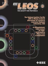
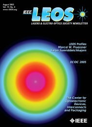
Figure 8: Experimentally obtained template to determine choice of<br />
grating periodicities for transmission dips at various wavelengths.<br />
Plot is for annealed gratings.<br />
Backreflection (dB)<br />
−88<br />
−91<br />
−94<br />
−97<br />
190 195 200<br />
Distance (mm)<br />
Figure 9: Optical coherence domain reflectometer (OCDR) trace<br />
showing the low back-reflection properties of the grating.<br />
power transfer to the cladding mode. Thus, n (and hence, κ g )<br />
is incre<strong>as</strong>ed until the condition κ g L = π/2 is met. Assuming<br />
complete transfer, the full width at half maximum (FWHM) λ<br />
of the spectral resonance defined by (5) is given approximately by<br />
λ =<br />
205 210<br />
0.8λ 2<br />
L(n eff − n cl ) . (6)<br />
Using the earlier example of a DSF with a grating with<br />
= 550 μm, L = 2.54 cm, and λ cut = 1.41 μm, we obtain<br />
from (6) a value of λ = 23 nm. Experimental results show<br />
this value to be in the 20–30 nm range for gratings with<br />
≈ 550–600 μm.<br />
Figure 10: <strong>Band</strong> rejection filter used in Raman amplifiers.<br />
Experiments<br />
Fabrication<br />
The experimental setup for grating fabrication is shown in Figure<br />
3. Hydrogen loaded germanosilicatc fibers were exposed to a KrF<br />
l<strong>as</strong>er (λ = 248 nm) through an amplitude m<strong>as</strong>k made of chromeplated<br />
silica. The optical threshold level for m<strong>as</strong>k damage w<strong>as</strong><br />
≈100 mJ/cm 2 per pulse. Each grating imprint on the m<strong>as</strong>k w<strong>as</strong><br />
one inch long, the duty cycle of the modulation structure w<strong>as</strong><br />
50% and grating periodicities ranged from 60 μm to 1 mm.<br />
Typical exposure conditions of energy = 250 mJ/pulse, pulse repetition<br />
frequency = 20 Hz and beam area = 2.6 × 1.1cm 2 were<br />
used. The transmission spectrum of the grating w<strong>as</strong> actively monitored<br />
<strong>as</strong> the grating w<strong>as</strong> being written. The peak loss and the<br />
peak wavelength incre<strong>as</strong>ed <strong>as</strong> a function of time, <strong>as</strong> shown in<br />
Figure 4. Fabrication times were in the 5–10 min range for fibers<br />
with 2–3% H 2 /D 2 and the number of gratings that could be<br />
batch-produced w<strong>as</strong> limited primarily by beam dimensions.<br />
Annealing<br />
UV-induced index changes in D 2 /H 2 loaded fibers occur when<br />
dissolved D 2 /H 2 reacts to form index-raising defects at Ge sites<br />
in the fiber core. After the UV-writing it is necessary to anneal<br />
the grating in order to stabilize its optical properties [17]. The<br />
anneal serves two purposes: 1) to outg<strong>as</strong> unreacted D 2 /H 2 which<br />
otherwise would raise the average index of the fiber and temporarily<br />
shift the grating peaks to longer wavelengths, and 2) to<br />
anneal out that portion of the UV-created sites which would be<br />
thermally unstable over long periods of time at normal operating<br />
temperatures. Appropriate anneal conditions will depend on<br />
the fiber and grating type, <strong>as</strong> well <strong>as</strong> on the anticipated operating<br />
temperature and the required stability of the grating device.<br />
Figure 5 shows results for the 150°C anneal of a grating written<br />
in a H 2 sensitized fiber. The rapid wavelength shift in the first<br />
several hours is primarily <strong>as</strong>sociated with the outg<strong>as</strong>sing of<br />
residual H 2 , while the more subtle long term changes are caused<br />
by the gradual decay of UV-induced defects.<br />
16 IEEE LEOS NEWSLETTER June 2007
Properties<br />
In Figure 6, we show the transmission spectrum of a strong<br />
grating of length 2.54 cm written with a grating period<br />
= 402 μm. The maximum loss is 32 dB at a peak wavelength<br />
λ p = 1517 nm, the 20 dB isolation point is<br />
4 nm wide, the 3 dB point (λ) is 22 nm, and the<br />
insertion loss is < 0.20 dB for wavelengths < 1480<br />
nm and > 1545 nm. Viewed over a broader wavelength<br />
range, a typical spectrum is shown in Figure<br />
7 (for a FLEXCOR fiber with = 198 μm) which<br />
clearly indicates the different cladding modes.<br />
Several different gratings with periodicities in the<br />
150–600 μm range were fabricated and the different<br />
peaks in the spectrum were categorized according to<br />
the different cladding mode orders. The experimental<br />
results of the complete DSF characterization are<br />
shown in Figure 8. One of the key features that distinguishes<br />
the long-period gratings from their shortperiod<br />
blazed counterparts is the ultra-low backreflection<br />
properties. An optical coherence domain<br />
reflectometer trace for a long-period grating is<br />
shown in Figure 9. The backreflection numbers<br />
are consistent with our estimate (b<strong>as</strong>ed on detailed<br />
growth and annealing experiments) of maximum<br />
UV-induced n of 5 × 10 −4 . A me<strong>as</strong>urement of<br />
polarization properties of these devices shows the<br />
polarization mode dispersion (PMD) < 0.01 ps and<br />
polarization dependent loss (PDL) < 0.02 dB.<br />
Applications<br />
The most common use of the long-period gratings is<br />
<strong>as</strong> a band-rejection filter and several applications<br />
have been explored. The grating of Figure 6 can be<br />
used <strong>as</strong> an ASE suppressor, presenting a near-transparent<br />
path to the pump (1480 nm) and signal<br />
wavelengths (> 1545 nm) in erbium-doped amplifiers.<br />
A band-rejection filter is also used to remove<br />
unnecessary Stokes’ orders in a c<strong>as</strong>caded Raman<br />
amplifier/l<strong>as</strong>er [18]. For example, the grating of<br />
Figure 10 is used to reject extraneous 1310 nm light<br />
while simultaneously allowing the 1240 nm pump<br />
wavelength to be transmitted with minimum loss.<br />
The band-gap filling effect [19] seen in Bragg-grating<br />
stabilized 980 nm pump-diodes can also be<br />
countered using a small band-rejection filter at<br />
∼ 1 μm. This effect is shown in<br />
Figure 11, where the tendency of the l<strong>as</strong>er to split its<br />
spectrum and l<strong>as</strong>e at λ >980 nm (thus rendering it<br />
ineffective for erbium pumping applications) is<br />
curbed by the addition of the filter whose transmission<br />
spectrum is shown in the inset [20]. In coarse<br />
WDM applications, it is often critical to insert a<br />
cleanup filter after the demultiplexer (at the receiver<br />
end) to remove vestiges of the channel that is not<br />
being monitored. For a 1310/1550 nm system, we<br />
can fabricate this filter by splicing two gratings separated<br />
by a few nanometers in peak wavelength.<br />
Output Power (dBm)<br />
Output Power (dBm)<br />
−30<br />
−40<br />
−50<br />
−60<br />
−70<br />
With concatenation, we have fabricated devices with a 15 dB<br />
bandwidth of 20 nm, a 20 dB bandwidth of 10 nm<br />
(centered around 1555 nm), with an insertion loss < 0.20 dB<br />
at 1310 nm.<br />
−80<br />
950 975 1000 1025<br />
−35<br />
−45<br />
−55<br />
−65<br />
Wavelength(nm)<br />
Figure 11: Effect of band-rejection filters on grating-stabilized<br />
980 nm pump diodes. (a) Bragg-grating stabilized semiconductor pump diode<br />
shows a split in the spectrum. (b) The addition of a long-period grating moves<br />
the peak l<strong>as</strong>ing wavelength toward 980 nm. Inset shows transmission spectrum<br />
of long-period grating [20].<br />
June 2007 IEEE LEOS NEWSLETTER 17<br />
Transmission (dB)<br />
(a)<br />
0<br />
−1<br />
−2<br />
−3<br />
−4<br />
−5<br />
950 975 1000 1025 1050<br />
Wavelength (nm)<br />
−75<br />
950 975 1000 1025<br />
Wavelength(nm)<br />
(b)
1590<br />
1588<br />
1.5<br />
1560<br />
1557<br />
1586<br />
1554<br />
A<br />
Wavelength (nm)<br />
1584<br />
1582<br />
1580<br />
1530<br />
1528<br />
1526<br />
1524<br />
1522<br />
1520<br />
1.0<br />
2.0<br />
2.5<br />
0 20 40 60 80 100 120 140<br />
Temperature (°C)<br />
Wavelength (nm)<br />
1551<br />
1548<br />
1545<br />
1273<br />
1270<br />
1267<br />
1264<br />
1261<br />
1258<br />
1255<br />
B<br />
0.0 0.2 0.4 0.6 0.8 1.0<br />
Strain (%)<br />
Figure 12: Effect of grating length on temperature dependence.<br />
Numbers indicate lengths of gratings in centimeters.<br />
Environmental Effects<br />
The characteristics of long-period fiber gratings are affected<br />
by external perturbations such <strong>as</strong> strain, temperature and<br />
bends. The effect is primarily due to a differential change<br />
induced in the two modes. More specifically, since the propagation<br />
constants β 01 and β (n)<br />
cl undergo dissimilar changes<br />
owing to a change in the external conditions, the difference<br />
between the two modes, β, is altered. For a fixed periodicity<br />
one h<strong>as</strong> to shrink or stretch the β-axis of Figure 1,<br />
implying a shift in the wavelength of resonant coupling<br />
between the two modes.<br />
The temperature dependence of the peak wavelength in<br />
the transmission spectrum for four different lengths of<br />
gratings written in DSF’s is shown in Figure 12. The slope<br />
is found to vary from 0.04–0.05 nm/°C. We see that neither<br />
the length of the grating nor the peak wavelength significantly<br />
affects the temperature sensitivity and may further<br />
imply that the predominant factor responsible for the<br />
effect is the differential-mode propagation constant. By<br />
means of comparison, a Bragg grating peak wavelength<br />
shifts by about 1.1 nm for a 100°C change (slope ≈0,01<br />
nm/°C). The effect of strain on the grating is more<br />
dependent on the type of fiber. The variations in peak<br />
wavelengths with strain for two different fibers are plotted<br />
in Figure 13. Grating A exhibits a slope of −0.7 nrn/mε,<br />
while grating B h<strong>as</strong> a slope of +1.5 nrn/mε. This dramatic<br />
dependence on the fiber type is currently being studied.<br />
In comparison, Bragg gratings Show a strain dependence<br />
of +1.0 to +1.8 nrn/mε.<br />
The effect of bending and recoating on long-period gratings<br />
is important from a practical viewpoint since it directly<br />
determines the packaging method of choice. Small bends<br />
in the fiber gratings can completely w<strong>as</strong>h out the grating<br />
properties, with the peak isolation falling to less than 3 dB<br />
(from 20 dB) and the peak wavelength shifting to the shorter<br />
side. The loss and shift in the transmission dip is thought<br />
Figure 13: Effect of strain on the peak wavelength of two different<br />
gratings.<br />
to be due to two causes: 1) Bending the fiber destroys the<br />
constant reinforcement in the coupling between the core and<br />
the cladding modes since the cladding mode is being forced<br />
out at the cladding-air interface, and 2) Bending changes the<br />
effective cladding mode index thus tending to alter the<br />
wavelength characteristics. As a consequence, the package<br />
design should be chosen with no allowance for slack. This<br />
may also imply that these gratings cannot be routinely<br />
recoated and spooled, <strong>as</strong> may be desirable in some applications<br />
where packaging real-estate is at a premium. Recoating<br />
the gratings adds to the complexity of design, <strong>as</strong> we show<br />
below.<br />
Recoating the grating with a conventional polymer (used<br />
for recoating splices) reduces the peak isolation by <strong>as</strong> much <strong>as</strong><br />
10 dB. The change in grating characteristics is <strong>as</strong>cribed to the<br />
absorptive nature of the coating which affects the cladding<br />
mode properties. One can use low-index polymer coatings currently<br />
being developed for cladding-pumped l<strong>as</strong>er applications<br />
to maintain the guiding properties of the cladding. A<br />
low-index (n = 1.38) polymer coating w<strong>as</strong> applied to a grating<br />
whose transmission spectrum had three peaks at<br />
λ 1 = 1479.0 nm, λ 2 = 1510.2 nm, and λ 3 = 1564.2 nm,<br />
corresponding to the coupling of the LP 01, core , to the LP 01, cl ,<br />
LP 02, cl , and LP 03, cl modes, respectively. After recoating, the<br />
three peaks shifted by −0.4, −1.2, and −2.4 nm, respectively.<br />
The shift to shorter wavelengths is expected since the application<br />
of the coating raises the effective index of the cladding<br />
modes and from Figure 1, we can see that the β-axis needs to<br />
be stretched (ω ↑, λ↓) to match the grating vector to the<br />
differential propagation constants. The relative amplitudes of<br />
these shifts are consistent with the relative mode confinement.<br />
For example, it is re<strong>as</strong>onable to expect that the polymer coating<br />
will have a greater effect on the LP 02, cl mode (with two<br />
intensity peaks spread further into the cladding) than the<br />
more tightly confined LP 01, cl mode. These observations add<br />
another consideration to grating design if recoating is a neces-<br />
18 IEEE LEOS NEWSLETTER June 2007
sary step during packaging. For minimum<br />
spectral shifts after recoating, one<br />
should choose the grating periodicity<br />
such that the LP 01, core mode couples to<br />
the first cladding mode.<br />
Conclusion<br />
We have presented a new cl<strong>as</strong>s of<br />
long-period gratings that function <strong>as</strong><br />
spectrally selective loss elements.<br />
Natural extensions of these gratings<br />
are in spectral shape-shifting applications,<br />
whereby the spectrum of an<br />
existing system can be modified with<br />
the use of these in-fibe’r devices.<br />
Gain-flattening devices for erbiumdoped<br />
liber amplifiers, and sensors<br />
for me<strong>as</strong>uring strain, temperature,<br />
and refractive index have been<br />
demonstrated. Other applications<br />
such <strong>as</strong> switching and power monitoring<br />
are currently being explored.<br />
In summary, these all-fiber fillers are<br />
versatile devices with low insertion<br />
losses (< 0.2 dB), low back-reflections<br />
(< −80 dB), excellent polarization<br />
insensitivity (PMD < 0.01 ps,<br />
PDL < 0.02 dB) and midband peak<br />
losses (band rejection) reaching <strong>as</strong><br />
high <strong>as</strong> 30 dB.<br />
Acknowledgment<br />
The authors would like to thank V.<br />
Mizrahi, K.L. Walker, and I.A.<br />
White for useful discussions, W.A.<br />
Reed for help in modeling fiber-dispersion<br />
curves, G. Jacobovitz-<br />
Veselka for providing the data in<br />
Figure 11, D.S. G<strong>as</strong>per for<br />
PMD/PDL me<strong>as</strong>urements, and S.G.<br />
Kosinski for recoating gratings.<br />
We are grateful to Photonetics, Inc.,<br />
for the use of the high-sensitivity<br />
OCDR.<br />
References<br />
[1] M.C. Parries, C.M. Ragdale,<br />
and D.C.J. Reid, “Broadband<br />
chirped fiber Bragg filters for<br />
pump rejection and recycling in<br />
erbium doped fiber amplifiers,”<br />
Electron. Lett., vol. 28, pp.<br />
487–489, 1992.<br />
[2] P.J. Lemaire, R.M. Atkins, V.<br />
Mizrahi, and W.A. Reed, “High<br />
pressure hydrogen loading <strong>as</strong> a<br />
technique to achieving ultrahigh<br />
uv-photosensitivity and<br />
thermal sensitivity in GeO 2<br />
doped optical fibers,” Electron.<br />
Lett., vol. 29, pp. 1191–1193,<br />
1993.<br />
[3] G. Meltz, W.W. Morey, and<br />
W.H. Glenn, “Formation of<br />
Bragg gratings in optical fibers<br />
by transverse holographic<br />
method,” Opt. Lett., vol. 14, pp.<br />
823–825, 1989.<br />
[4] G.A. Ball and W.W. Morey,<br />
“Continuously tunable singlemode<br />
fiber l<strong>as</strong>er,” Opt. Lett., vol.<br />
17, pp. 420–422, 1992.<br />
[5] V. Mizrahi, D.J. DiGiovanni,<br />
R.M. Atkins, S.G. Grubb, Y.-<br />
K. Park, and J.-M. Delavaux,<br />
“Stable single mode erbium<br />
fiber grating l<strong>as</strong>er for digital<br />
communication,” J. Lightwave<br />
Technol., vol. 11, pp.<br />
2021–2025, 1993.<br />
[6] K.O. Hill, B. Malo, K.<br />
Vineberg, F. Bilodeau, D.<br />
Johnson, and I. Skinner,<br />
“Efficient mode-conversion in<br />
telecommunication fiber using<br />
externally written gratings,”<br />
Electron. Lett., vol. 26, pp.<br />
1270–1272, 1990.<br />
[7] F. Bilodeau, K.O. Hill, B. Malo,<br />
D. Johnson, and L. Skinner,<br />
“Efficient narrowband LP 01 ↔<br />
LP 02 mode converters fabricated<br />
in photosensitive fiber: Spectral<br />
response,” Electron. Lett., vol.<br />
27, pp. 682–684, 1991.<br />
[8] K.O. Hill, F. Bilodeau, B.<br />
Malo, and D.C. Johnson,<br />
“Birefringent photosensitivity<br />
in monomode fiber:<br />
Application to external writing<br />
of rocking filters,” Electron.<br />
Lett., vol. 27, pp. 1548–1550,<br />
1991.<br />
[9] D.C. Johnson, F. Bilodeau, B.<br />
Malo, K.O. Hill, P.G.J. Wigley,<br />
and G.I. Stegeman, “<strong>Long</strong>length<br />
long-period rocking filters<br />
fabricated from conventional<br />
monomode telecommunications<br />
optical fiber,” Opt. Lett.,<br />
vol. 17, pp. 1635–1637, 1992.<br />
[10] T. Lenahan, “Calculation of<br />
modes in an optical fiber using<br />
the finite element method and<br />
EISPACK,” Bell Syst. Tech. J.,<br />
vol. 62, pp. 2663–2694, 1983.<br />
[11] M.J. Adams, An Introduction to<br />
Optical Waveguides. New York:<br />
Wiley-Interscience, 1981, sect. 7.2.<br />
[12] T. Erdogan and J.E. Sipe,<br />
“Tilted fiber ph<strong>as</strong>e gratings,” J.<br />
Opt. Soc. Amer. A, to be published.<br />
[13] V. Mizrahi and J.E. Sipe,<br />
“Optical properties of photosensitive<br />
fiber ph<strong>as</strong>e gratings,”<br />
J. Lightwave Technol., vol, 11,<br />
pp. 1513–1517, 1993.<br />
[14] M. Abramowitz and I.A. Stegun,<br />
Handbook of Mathematical<br />
Functions. New York: Dover,<br />
1992, p. 409.<br />
[15] D.G. Hall, Ed., Selected Papers on<br />
Coupled-Mode Theory in Guided<br />
Wave Optics. Bellingham, WA:<br />
SPIE Optical Engineering<br />
Press, 1993.<br />
[16] D.G. Hall, “Theory of waveguides<br />
and devices,” in<br />
Integrated Optical Circuits and<br />
Components, L.D. Hutcheson,<br />
Ed. New York: Marcel-Dekker,<br />
1987, eq. (2.143).<br />
[17] T. Erdogan, V. Mizrahi, P.J. Lemaire.<br />
and D. Monroe, “Decay of ultraviolet-induced<br />
fibsrBragg gratings,”<br />
J. Appl. Phys., vol. 75, pp. 73–80,<br />
1994.<br />
[18] S.G. Grubb, T. Erdogan, V.<br />
Mizrahi, T. Str<strong>as</strong>ser, W.Y.<br />
Cheung, W.A. Reed, P.J.<br />
Lemaire, A.E. Miller, S.G.<br />
Kosinski, G. Nykolak, and P.C.<br />
Becker, “1.3 μm c<strong>as</strong>caded<br />
Raman amplifier in germanosilicate<br />
fibers,” in Proc. Optic.<br />
Amplifiers Meet., CO, Aug. 3–5,<br />
1994, Postdeadline Paper PD3.<br />
[19] C.R. Giles, T. Erdogan, and V.<br />
Mizrahi, “Reflection-induced<br />
changes in the optical spectra of<br />
980-nm QW l<strong>as</strong>ers,” IEEE<br />
Photon: Technol. Lett., vol. 6, pp.<br />
907–909, 1994.<br />
[20] G. Jacobovitz-Veslka, P.F.<br />
Wysocki, A.M. Vengsarkar,<br />
J.M. Borick, T. Erdogan, V.<br />
Mizrahi, and S.W. Granlund,<br />
“Single-stage booster amplifier<br />
with two 980 nm pumps stabilized<br />
by fiber gratings,” in Proc.<br />
Optic. Amplifiers Meet., Davos,<br />
Switzerland, June 1995, Paper<br />
FC4.<br />
June 2007 IEEE LEOS NEWSLETTER 19