Couplers - Narda
Couplers - Narda
Couplers - Narda

You also want an ePaper? Increase the reach of your titles
YUMPU automatically turns print PDFs into web optimized ePapers that Google loves.
Power Monitors<br />
and Sensors<br />
RF Switching<br />
Products<br />
Passive<br />
Components<br />
Integrated Microwave<br />
Assemblies (IMAs)<br />
Introduction<br />
<strong>Couplers</strong><br />
microwave-east<br />
an<br />
company<br />
67
Introduction<br />
Integrated Microwave<br />
Assemblies (IMAs)<br />
Passive<br />
Components<br />
RF Switching<br />
Products<br />
Power Monitors<br />
and Sensors<br />
<strong>Couplers</strong><br />
Quick Reference Guide<br />
FREQUENCY<br />
RANGE (GHz)<br />
MODEL<br />
SERIES<br />
CONNECTOR<br />
PAGE<br />
1-40 4229 2.92 mm 76<br />
18-40 4018 2.92 mm 76<br />
1.7-26.5 4227 2.92 mm 80<br />
6-26.5 4247 2.92 mm 80<br />
18-26.5 4017 2.92 mm 80<br />
0.5 -18 4226 SMA 85<br />
1-18 3222 Type N 84<br />
1-18 3292 Type N 99<br />
1-18 4222 SMA 84<br />
1-18 5292 7 mm 99<br />
2-18 3060 Type N 95<br />
2-18 3203 Type N 84<br />
2-18 4203 SMA 84<br />
2-18 27000 Type N 87<br />
2-18 27003 TNC 87<br />
6-18 4196 SMA 86<br />
6-18 4246B SMA 82<br />
6-18 27001A Type N 87<br />
6-18 27004A TNC 87<br />
7-18 3096 7 mm 97<br />
12.4-18 4016C SMA 78<br />
12.4-18 4016D SMA 78<br />
7.5-16 4055 SMA 78<br />
1-12.4 3202B Type N 84<br />
1-12.4 4202B SMA 84<br />
4-12.4 4245B SMA 82<br />
7-12.4 3045C Type N 93<br />
7-12.4 3095 7 mm 97<br />
7-12.4 4015C SMA 78<br />
4-10 3004 Type N 91<br />
FREQUENCY<br />
RANGE (GHz)<br />
MODEL<br />
SERIES<br />
CONNECTOR<br />
PAGE<br />
3.7-8.3 3094 7 mm 97<br />
0.5-8 4216 SMA 78<br />
2-8 4244 SMA 82<br />
2-8 27002 Type N 87<br />
2-8 27002SC SC 89<br />
2-8 27005 TNC 87<br />
2-8 27005SC SC 89<br />
4-8 3024 Type N 95<br />
4-8 4014C SMA 78<br />
1.7-4.2 3043B Type N 93<br />
1.7-4.2 3093 7 mm 97<br />
2-4 3003 Type N 91<br />
2-4 4013C SMA 78<br />
1-4 3022 Type N 95<br />
1-3.5 4243 SMA 82<br />
0.7-2.5 3171 Type N 101<br />
0.92-2.2 3042B Type N 93<br />
0.95-2.2 3092 7 mm 97<br />
1.7-2.1 3161 Type N 101<br />
1.7-2.1 4161 SMA 101<br />
0.5-2.0 4242 SMA 82<br />
0.95-2.0 3002 Type N 91<br />
1.0-2.0 4012C SMA 78<br />
0.05-1.0 3020A Type N 95<br />
0.5-1.0 4011C SMA 78<br />
0.82-0.98 3151 Type N 101<br />
0.82-0.98 4151 SMA 101<br />
0.46-0.95 3001 Type N 91<br />
0.225-0.460 3000 Type N 91<br />
Environmental Performance for Selected Passive Products*<br />
PARAMETER<br />
SPECIFICATION<br />
Operating Temperature<br />
-54 to +105°C<br />
Storage Temperature<br />
-55 to +125°C<br />
Humidity<br />
Per MIL-STD-202F, method 103B, condition B (96 hours at 95% R.H.)<br />
Shock<br />
Per MIL-STD-202F, method 213B, condition J (30G, 11 msec)<br />
Altitude<br />
Per MIL-STD-202F, method 105G, condition B (50,000 feet)<br />
Vibration<br />
Per MIL-STD-202F, method 204D, condition B<br />
(.06" double amplitude or 15G, which ever is less)<br />
Thermal Shock<br />
Per MIL-STD-202F, method 107D, condition A (5 cycles)<br />
* Applicable to Stripline Directional <strong>Couplers</strong>, Attenuators, Power Dividers<br />
NOTE: This is an exclusive listing. Where otherwise noted in the catalog, the above environmental performance may not apply. Not applicable for those<br />
products designed for commercial applications. Many of our catalog off-the-shelf (COTS) products have the ability to withstand considerably more stringent<br />
environments. If you have special environmental requirements, please contact the Sales Department at <strong>Narda</strong>.<br />
68<br />
microwave-east<br />
an<br />
company<br />
www.nardamicrowave.com E-MAIL: nardaeast@L-3com.com TEL: +1 631 231-1700
Power Monitors<br />
and Sensors<br />
RF Switching<br />
Products<br />
Passive<br />
Components<br />
Integrated Microwave<br />
Assemblies (IMAs)<br />
Introduction<br />
<strong>Couplers</strong><br />
Introduction<br />
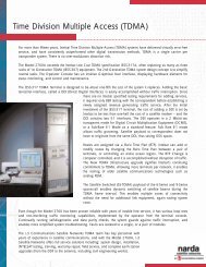
In today’s microwave practice, the directional coupler<br />
is a virtually indispensable measurement tool. It provides<br />
a simple, convenient, and accurate means for<br />
sampling microwave energy without moving parts and<br />
without the need for adjustments. Unlike other methods<br />
of power sampling involving probes or coupling<br />
loops, the directional coupler also provides the important<br />
capability of separating forward from reflected<br />
power. By selecting energy traveling only in one direction,<br />
as a function of the device directivity, accurate<br />
VSWR measurements can be facilitated, eliminating<br />
the mechanical motion needed with a slotted line.<br />
Attenuation measurements also become more accurate<br />
when directional couplers are used since reflection<br />
errors are eliminated.<br />
A<br />
C<br />
Coaxial Input<br />
Coaxial<br />
Coupled<br />
Output<br />
λ / 4 Coupled<br />
Section<br />
50 Ω<br />
Figure 1. Diagram of a typical directional coupler<br />
B<br />
Coaxial Output<br />
The basic construction of a coupled-line directional<br />
coupler can be seen in Figure 1, which illustrates a typical<br />
coaxial-line, microwave directional coupler such as<br />
might be used for microwave applications. It consists of<br />
two parallel striplines coupled over a length of approximately<br />
one-quarter wavelength. The mainline input (A)<br />
and output (B) coaxial lines are connected to one stripline;<br />
the other stripline is terminated in Z o<br />
at one end,<br />
and is connected to the coupled output port through<br />
a coaxial line (C). The two sections, referred to respectively<br />
as the main and auxiliary lines, are separated from<br />
each other except for the coupling area, through which<br />
energy is unidirectionally coupled from the main line to<br />
the auxiliary line. An internal view of a typical <strong>Narda</strong><br />
coaxial coupler is shown in Figure 2.<br />
Figure 2. Internal view of a typical coaxial coupler<br />
In operation, energy is fed into end A of the main line.<br />
Most of this energy will appear at the output end B.<br />
Some fraction of the energy, however, will appear at<br />
the output of the auxiliary line C, depending upon the<br />
amount of coupling provided in the design of the unit.<br />
Energy applied to end B of the main line will appear<br />
at A, but practically none of this energy will appear at<br />
the auxiliary output C. The degree of discrimination in<br />
the auxiliary line between energy flowing in the B to A<br />
direction and energy flowing in the A to B direction is<br />
the directivity of the coupler. Directivity is calculated as<br />
the ratio of the forward to reverse coupling, expressed<br />
in dB. Since the intention is to ensure that a minimum<br />
of reflected energy reaches the load on the auxiliary<br />
line, the ideal directional coupler will have an infinite<br />
value of directivity. The amount of coupling desired for<br />
forward power, however, will vary with the application.<br />
Consequently, coupling values from 6 dB to beyond 70 dB<br />
are frequently encountered.<br />
Types Of Directional <strong>Couplers</strong><br />
Although a wide variety of configurations and packages<br />
have been built, most directional couplers fall into<br />
a relatively small number of well-defined types according<br />
to the intended service and sampling capabilities.<br />
Typical categories are: waveguide or coaxial, single- or<br />
dual-directional units, and combination types.<br />
Coaxial directional couplers are offered for use at frequencies<br />
from 10 MHz to 40 GHz, and can be obtained<br />
with any of the standard or precision miniature coaxial<br />
www.nardamicrowave.com E-MAIL: nardaeast@L-3com.com TEL: +1 631 231-1700<br />
microwave-east<br />
an<br />
company<br />
69
Introduction<br />
<strong>Couplers</strong><br />
Integrated Microwave<br />
Assemblies (IMAs)<br />
Passive<br />
Components<br />
RF Switching<br />
Products<br />
Power Monitors<br />
and Sensors<br />
connectors. Dual directional couplers, which permit<br />
simultaneous sampling of both forward and reflected<br />
energy, consist essentially of two directional couplers<br />
connected back to back in a single package and are<br />
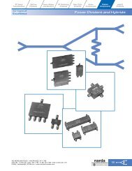
available for coaxial systems. Figure 3 shows typical<br />
<strong>Narda</strong> directional coupler configurations.<br />
FIgure 3. High Directivity Directional <strong>Couplers</strong><br />
In addition, as special-order devices, a number of<br />
combination types are available, such as those which<br />
include couplers combined with detectors, referred to<br />
as directional detectors. For some applications, couplers<br />
are designed without the internal termination in<br />
the secondary line, permitting the user to terminate<br />
that line either with an absorbing load of his selection<br />
or with other RF instrumentation as desired.<br />
Selection Features<br />
Published specifications for directional couplers usually<br />
include coupling, directivity, insertion loss, main line<br />
and auxiliary line VSWR, bandwidth, frequency sensitivity<br />
and power handling capability. These and other<br />
terms commonly used in specifying coupler characteristics<br />
are defined below.<br />
Coupling Coefficient - The ratio in dB of the incident<br />
power fed into the main port, to the coupled port<br />
power when all ports are terminated by reflectionless<br />
terminations. Some <strong>Narda</strong> couplers are principally used<br />
for power leveling, and the coupling coefficient of these<br />
couplers is expressed as the ratio in dB of the main-line<br />
power output to the power output at an auxiliary port.<br />
Directivity - The ratio in dB of the power output at<br />
an auxiliary port, when power is transmitted in the<br />
preferred direction, to the power output at the same<br />
auxiliary port when the same amount of power is<br />
transmitted in the opposite direction. Reflectionless<br />
terminations are connected to all ports.<br />
Insertion Loss - The change in load power, due to the<br />
insertion of a component in a transmission system,<br />
reflectionless terminations being connected to the<br />
ports of the inserted component.<br />
Residual VSWR - The standing wave ratio measured by<br />
a reflectometer coupler terminated by a reflectionless<br />
termination, and fed from a nonreflecting generator.<br />
(Directivity or return loss expressed as a VSWR.)<br />
Bandwidth - The range of frequencies within which<br />
performance, with respect to some characteristic, falls<br />
within specific limits.<br />
Frequency Sensitivity (or Flatness) - The maximum<br />
peak-to-peak variation in coupling coefficient over a<br />
specified frequency band.<br />
Tracking - The maximum change in the difference of<br />
the coupling coefficient ratio of two coupler paths.<br />
The relative importance of each of these characteristics<br />
will, of course, vary with the particular application. It<br />
should be noted that some of these characteristics tend<br />
to conflict; for example, it is difficult to obtain both<br />
flatness over a broad bandwidth and high directivity.<br />
Selection of a coupler for each application thus requires<br />
evaluating the major performance parameters in terms<br />
of the intended service.<br />
Coupling Coefficient<br />
<strong>Narda</strong> directional couplers are offered in a choice<br />
of convenient standard and non-standard coupling<br />
values. While the standard coupling values of 6, 10, 20<br />
and 30 dB are most common, several catalog models<br />
are available in alternative coupling values (13 or 16 dB,<br />
for example), including devices that provide up to 60 dB<br />
of coupling.<br />
As is the case with the majority of our family of passive<br />
products, special models are available if they<br />
are required. Since our ability to provide a special<br />
coupler will be gated by the particulars of the requirement<br />
(volume factors, cost factors, etc.), we will often<br />
recommend the use of a standard-value coupler in conjunction<br />
with a fixed precision attenuator attached to<br />
the coupled port. With this configuration, any number<br />
of non-standard coupling values can be achieved very<br />
cost effectively.<br />
The choice of the specific value of coupling coefficient<br />
will usually depend upon the power levels<br />
70<br />
microwave-east<br />
an<br />
company<br />
www.nardamicrowave.com E-MAIL: nardaeast@L-3com.com TEL: +1 631 231-1700
Power Monitors<br />
and Sensors<br />
RF Switching<br />
Products<br />
Passive<br />
Components<br />
Integrated Microwave<br />
Assemblies (IMAs)<br />
Introduction<br />
<strong>Couplers</strong><br />
involved. Where auxiliary (coupled) output is used to<br />
feed a measuring device, the coupling must provide<br />
adequate signal levels without overloading the equipment.<br />
It must be remembered, also, that any coupler<br />
takes power out of the main line, the magnitude of this<br />
drain being dependent upon the amount of coupling<br />
between the main and auxiliary lines. For example a<br />
20 dB coupler will reduce the transmitted power by 1%,<br />
while a 6 dB coupler will reduce the transmitted power<br />
by 25%. In specifying coupling coefficient, therefore, it<br />
may be necessary to consider the amount of power loss<br />
that can be tolerated in the portion of the system following<br />
the coupler.<br />
Coupling coefficient is measured with an absolute<br />
accuracy of ±0.1 dB per 10 dB. Flatness is measured to<br />
an accuracy of ±0.05 dB relative to other points.<br />
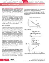
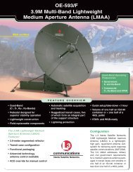
DIRECTIVITY - dB<br />
50.0<br />
45.0<br />
40.0<br />
35.0<br />
30.0<br />
25.0<br />
1.0 2.0 3.0 4.0 5.0 6.0 7.0 8.0 9.0 10.0 11.0 12.0 13.0 14.0 15.0 16.0 17.0 18.0<br />
FREQUENCY - GHz 12.4<br />
Figure 4. Typical directivity curve for Models 3292 and 5292<br />
Broadband High Directivity <strong>Couplers</strong><br />
Directivity<br />
In power measurements, the degree to which the<br />
auxiliary line is isolated from the load is of particular<br />
importance where high measurement accuracy is<br />
required. In power measuring application, where the<br />
absolute magnitude of the sample is the significant<br />
value, reverse coupling into the auxiliary line will alter<br />
the magnitude of this sample, with resulting measurement<br />
error. Errors from reflected power can be severe<br />
when the directivity is not adequate. In reflectometry,<br />
where the VSWR of a test piece is measured, accuracy is<br />
closely dependent upon the directivity of the coupler<br />
used. Here the effect of poor directivity is to introduce<br />
a residual reflection which adds to or subtracts from the<br />
reflected energy of the device. The graph in Figure 4<br />
shows a typical directivity curve for <strong>Narda</strong> Models 3292<br />
and 5292 Broadband High Directivity <strong>Couplers</strong>. These<br />
devices provide the hightest broadband directivity performance<br />
available.<br />
Insertion Loss<br />
The term “insertion loss” has the same significance with<br />
respect to directional couplers as for other components<br />
in a microwave system. That is, it describes the loss<br />
resulting from the insertion of the device into a transmission<br />
system.<br />
<strong>Narda</strong> couplers now carry two insertion loss specifications:<br />
insertion loss, in accordance with the industry<br />
standard definition (see page 70); and insertion loss,<br />
excluding coupled power. This latter term allows for<br />
some ambiguity in characterizing couplers with coupling<br />
coefficients less than 15 dB. It is calculated value<br />
based on what the insertion loss would be if no power<br />
were coupled to the auxiliary port or ports. The insertion<br />
loss “excluding coupled power” specification is<br />
given in this catalog (where applicable) for reference<br />
only.<br />
Voltage Standing Wave Ratio (VSWR)<br />
In waveguide couplers, where coupling between main<br />
and auxiliary line is accomplished through holes or slots,<br />
VSWR can be held to very low levels, often no greater<br />
than that resulting from a typical flange mismatch. In<br />
coaxial couplers, the proximity effects, end effects and<br />
capacitive effects from the coupling bars employed<br />
generally result in higher values of VSWR. The major<br />
source of high VSWR in coaxial couplers, however, is<br />
usually found in the connectors employed. The particular<br />
structure of standard coaxial connectors introduces<br />
an appreciable amount of reflection. Consequently,<br />
where the application requires minimum reflection<br />
back into the main line, precision laboratory connectors<br />
are required.<br />
Bandwidth<br />
For laboratory applications, it is customary to select<br />
couplers with as broad a bandwidth as possible, simply<br />
because broad bandwidth affords greater flexibility in<br />
handling the changing day-to-day measurement tasks.<br />
Where bandwidth is under consideration it should be<br />
noted, however, that broad frequency range is usually<br />
accompanied by reduced directivity and increased<br />
VSWR. For very narrow bandwidths it is possible to<br />
maintain coupling coefficient to within 0.1 dB of nominal<br />
value and to achieve directivities over 40 dB. Where<br />
the coupler is required to operate over an octave frequency<br />
band the coupling tolerance may have to be<br />
www.nardamicrowave.com E-MAIL: nardaeast@L-3com.com TEL: +1 631 231-1700<br />
microwave-east<br />
an<br />
company<br />
71
Introduction<br />
<strong>Couplers</strong><br />
Integrated Microwave<br />
Assemblies (IMAs)<br />
Passive<br />
Components<br />
RF Switching<br />
Products<br />
Power Monitors<br />
and Sensors<br />
increased. Thus, when a choice is possible, it is best to<br />
specify the narrowest bandwidth compatible with the<br />
application requirements.<br />
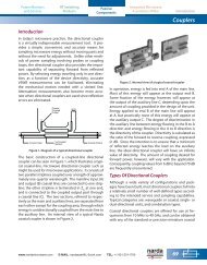
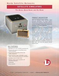
Frequency Sensitivity<br />
Directional couplers are available in single and multisection<br />
design. Single (1/4 λ) section couplers exhibit<br />
frequency response similar to that shown in Figure 5,<br />
Curve A. The multi-section type couplers exhibit a<br />
flat frequency response over their frequency range as<br />
shown in Figure 5, Curve B.<br />
COUPLING - dB<br />
13.0<br />
12.5<br />
12.0<br />
11.5<br />
11.0<br />
10.5<br />
10.0<br />
9.5<br />
9.0<br />
S BAND<br />
1.5 2 2.25 2.5 2.75 3 3.5 4 4.5 5<br />
Figure 5. Typical response curves of single and multi-section<br />
directional couplers. Curve A represents 1/4λ; Curve B represents<br />
maximally flat response curve.<br />
Where a band of frequencies must be sampled, as<br />
in swept-frequency measurements, the “flatness” or<br />
frequency sensitivity of the coupler is of major importance.<br />
Manufacturers differ in the method of specifying<br />
frequency sensitivity. In some instances, variation of<br />
coupling with frequency is expressed as the deviation<br />
from the nominal value; in others, as the excursion<br />
around the mean value of coupling over the range.<br />
Where couplers are to be used over a band of frequencies,<br />
manufacturers may provide a calibration chart<br />
showing the actual coupling as specified frequencies<br />
across the band. The <strong>Narda</strong> Model 3040 Series Maximally<br />
Flat Directional <strong>Couplers</strong> have a flatness specification of<br />
±0.25 dB over an extended band and are, in addition,<br />
calibrated at five points within the octave.<br />
Power Rating<br />
Power ratings for directional couplers are usually specified<br />
for both CW power and peak pulse power, in both<br />
the forward and reverse directions. These ratings represent<br />
the maximum levels at which the unit can operate<br />
without altering its characteristics and/or cause irreversible<br />
damage to the device.<br />
A<br />
B<br />
NOTE: For applicable <strong>Narda</strong> <strong>Couplers</strong>, <strong>Narda</strong> can supply<br />
standard test data for a nominal fee.<br />
Applications<br />
Power Measurements<br />
Although the directional coupler finds a variety of uses<br />
as a power “splitter,” in many applications it is used as<br />
a calibrated power sampler in a measurement system.<br />
Among its most common applications is the measuring<br />
or monitoring of microwave power. Because it can<br />
sample transmission line power by a definite known<br />
amount, accurate measurements can be conveniently<br />
made without interrupting operation of the system.<br />
The accuracy of measurement with a given detectormeter<br />
combination will depend upon the accuracy of<br />
sampling, that is, upon the absolute magnitude of the<br />
coupling. With the coupling coefficient known, the<br />
meter may be calibrated to provide a direct indication<br />
of power at the input to the coupler. Figure 6 is an<br />
example of such an application.<br />
Magnetron<br />
R. F. Unit<br />
Power<br />
Meter<br />
Detector<br />
Directional<br />
Coupler<br />
Antenna<br />
Figure 6. Directional couplers and power meters used for<br />
measuring power in the microwave portion of a radar system.<br />
Frequency Measurements<br />
The directional coupler is especially useful in measuring<br />
or monitoring frequency in operating systems since<br />
it permits measurements without disrupting operation.<br />
The requirement for uninterrupted operation, without<br />
interference from the measuring device, is met by using<br />
a resonant cavity wavemeter or a direct reading counter<br />
in conjunction with a directional coupler.<br />
Signal Leveling<br />
In swept frequency measurements, some form of signal<br />
leveling is virtually mandatory. Although sweep generators<br />
are available with leveled outputs, an external<br />
closed loop method of leveling is usually necessary to<br />
eliminate uncertainties introduced by cables and other<br />
components between the generator and the test piece.<br />
72<br />
microwave-east<br />
an<br />
company<br />
www.nardamicrowave.com E-MAIL: nardaeast@L-3com.com TEL: +1 631 231-1700
Power Monitors<br />
and Sensors<br />
RF Switching<br />
Products<br />
Passive<br />
Components<br />
Integrated Microwave<br />
Assemblies (IMAs)<br />
Introduction<br />
<strong>Couplers</strong><br />
Such a leveling loop can be conveniently arranged<br />
through the use of a directional coupler and detector.<br />
Reflection Coefficient Measurements<br />
The ability of swept-frequency techniques to provide<br />
broadband plots of microwave reflection characteristics<br />
(in a fraction of the time required for point-by-point<br />
measurements) affords obvious advantages. Speed<br />
and convenience are provided where testing time<br />
and costs are important considerations. Recognition<br />
of these advantages led to continuing refinement of<br />
swept-frequency reflectometer systems. As a result, a<br />
choice of swept-frequency techniques is now available<br />
for measuring reflection coefficient and VSWR in coaxial<br />
components, providing both the accuracy demanded<br />
for laboratory work and the speed and efficiency<br />
required for production-line testing. Improvements<br />
in coupler design and manufacturing techniques<br />
have significantly increased the accuracy of coaxial<br />
reflectometry. Today’s reflectometer couplers provide<br />
directivities as much as an order of magnitude greater<br />
than previously obtainable.<br />
In applications such as production-line testing, the<br />
reflectometer is a common method of measuring<br />
reflection coefficient, VSWR and impedance since this<br />
method offers advantages of speed and convenience,<br />
as the dual directional coupler (incorporating two auxiliary<br />
outputs) permits the simultaneous sampling of<br />
incident and reflected power.<br />
Purpose and Use of Equipment<br />
Reflectometer couplers offer a significant cost savings<br />
over microwave vector network analyzers for<br />
production test stations and monitoring VSWR during<br />
environmental testing. The test set-up consists of a<br />
sweep generator, matching attenuator or isolator, scalar<br />
network analyzer, and a precision laboratory reflectometer<br />
coupler (<strong>Narda</strong> 3090 Series, 3020A, 3022, 3024 Dual<br />
<strong>Couplers</strong> and 3292 Broadband <strong>Couplers</strong>). Data can be<br />
stored in an electronic file or plotted for a paper copy.<br />
The reflectometer is excellent for detecting intermittent<br />
problems while a unit is under environmental test.<br />
Principles of Reflectometer Operation<br />
The reflectometer coupler consists of two precision airline<br />
directional couplers, with rigid structure enclosing<br />
the two couplers to ensure protection for the critical<br />
parts of the coupling mechanism. The coupled line<br />
impedances have been perfectly balanced.<br />
Discontinuities where the transmission line connects<br />
to the coupling mechanism and at bead supports<br />
are designed for broadband impedance match to<br />
achieve the desired high directivity. Since the twin<br />
couplers are effectively positioned back-to-back, a<br />
portion of the RF microwave power applied to the<br />
input port is coupled out of the incident power port<br />
at a level 10 dB down from the applied power level.<br />
The remainder of applied power appears at the main<br />
line output port and is applied to the load. Coupling<br />
variations (also referred to as frequency sensitivity)<br />
between the main line input and coupled incident<br />
output ports are calibrated at five discrete frequencies<br />
within the octave bandwidth and vary not more<br />
than ±1.0 dB from the nominal 20 dB coupling value.<br />
Figure 7. Directional Coupler with SC Connectors<br />
Figure 8. Coaxial Dual Directional Coupler<br />
www.nardamicrowave.com E-MAIL: nardaeast@L-3com.com TEL: +1 631 231-1700<br />
microwave-east<br />
an<br />
company<br />
73
Introduction<br />
<strong>Couplers</strong><br />
Integrated Microwave<br />
Assemblies (IMAs)<br />
Passive<br />
Components<br />
RF Switching<br />
Products<br />
Power Monitors<br />
and Sensors<br />
The ability of a dual directional coupler to provide an<br />
accurate measure of incident or reflected power is<br />
enhanced by the tracking between the incident and<br />
reflected output ports. Therefore, the coupling variation<br />
of frequency sensitivity of the reflected output port<br />
should ideally be identical to that of the incident output<br />
port. RF power applied to the load is reflected to some<br />
degree depending on load characteristics, thereby<br />
resulting in a voltage standing wave ratio (VSWR) which<br />
is reflected back to the main line output port. This<br />
reflected power is coupled out of the reflected output<br />
port at a level 10 dB down from the reflected power<br />
level at the load. Since the tracking of the forward and<br />
reverse ports is held to a total of 0.3 dB, the coupling<br />
variation at the reflected output port closely follows<br />
that of the incident output port.<br />
In addition to exhibiting excellent tracking characteristics,<br />
the dual directional coupler also features as high a<br />
directivity as possible. Directivity can be expressed as<br />
the ratio of power being coupled out of the reflected<br />
port, with the main line output terminated by a precision<br />
termination, to the power being coupled out of<br />
the incident port. If a portion of the incident power is<br />
coupled out of the reflected output port it essentially<br />
adds, randomly, to the reflected power from the load,<br />
thereby introducing an error. Likewise, if a portion of the<br />
reflected power appears at the incident output port, it<br />
adds to the normal incident coupled power. Therefore,<br />
a true measure of incident and reflected power for accurate<br />
determination of reflection coefficient and VSWR<br />
depends on coupler directivity; the higher the directivity,<br />
the more accurate the measurement. As previously<br />
mentioned, the reflectometer coupler exhibits a directivity<br />
of 45 dB minimum at L-band.<br />
The single-ended coupler is a single air-line directional<br />
coupler for use in measuring transmission gain or loss<br />
characteristics in a swept measurement setup with the<br />
reflectometer coupler, or for use in RF power measurement<br />
setups. Besides exhibiting similar high directivity<br />
to the reflectometer coupler, in each of the five bands,<br />
the coupled output port (10 dB) of this device also provides<br />
tracking (0.3 dB) with respect to the incident port<br />
of the reflectometer set. As a result, simultaneous measurement<br />
of reflection coefficient and transmission gain<br />
or loss characteristics is possible in a single swept measurement<br />
system.<br />
Design Theory<br />
A coaxial directional coupler has the general appearance<br />
of a section of coaxial line, with the addition of a<br />
second parallel section of line and with one end terminated<br />
(see Figure 9).<br />
MAIN<br />
LINE<br />
INPUT<br />
A<br />
AUXILIARY<br />
LINE OUTPUT<br />
(COUPLED OUTPUT)<br />
C<br />
AUXILIARY<br />
LINE<br />
MAIN LINE<br />
INTERNAL<br />
TERMINATIONS<br />
Figure 9. Single-Ended Coaxial Directional Coupler<br />
A<br />
C = P 1<br />
B<br />
C = P 2<br />
MAIN<br />
LINE<br />
INPUT<br />
These two sections are known as the main and auxiliary<br />
lines. The two lines are internally separated from each<br />
other; the amount of spacing between lines determines<br />
the amount of RF energy that may be transferred from<br />
the main line to the auxiliary line. In operation, assume<br />
that energy is fed into port A of the main line. Most of<br />
this energy will appear at output port B of the main line.<br />
However, a fraction of this energy (determined by coupling<br />
value) will also appear at the coupled port C, of<br />
the auxiliary line.<br />
A dual-directional coaxial coupler, such as the reflectometer<br />
coupler, consists essentially of two single-ended<br />
couplers connected back-to-back. Perhaps the most<br />
important characteristic of the directional coupler (and<br />
the one from which its name originates) is its directivity.<br />
Directivity and Coupling<br />
Directivity means that energy entering output port B of<br />
the main line will appear at input port A, but practically<br />
none of the energy will appear at coupled output port<br />
C of the auxiliary line. This characteristic has wide application<br />
in the measurement of RF microwave power. The<br />
coupling of a directional coupler, therefore, is the ratio<br />
of the power fed into input port A of the main line to the<br />
power appearing at output port C of the auxiliary line; it<br />
is usually expressed in decibel (dB) and is calculated in<br />
the same manner as any other form of attenuation.<br />
Directivity is a measure of isolation obtainable at coupled<br />
port C with power being fed into the main line<br />
at output port B. Directivity is calculated in the same<br />
B<br />
74<br />
microwave-east<br />
an<br />
company<br />
www.nardamicrowave.com E-MAIL: nardaeast@L-3com.com TEL: +1 631 231-1700