Section 5. Flash Programming - Microchip Taiwan
Section 5. Flash Programming - Microchip Taiwan
Section 5. Flash Programming - Microchip Taiwan

Create successful ePaper yourself
Turn your PDF publications into a flip-book with our unique Google optimized e-Paper software.
<strong>Section</strong> <strong>5.</strong> <strong>Flash</strong> <strong>Programming</strong><br />
This section of the manual contains the following major topics:<br />
<strong>5.</strong>1 Introduction .................................................................................................................... 5-2<br />
<strong>5.</strong>2 Table Instruction Operation ............................................................................................5-2<br />
<strong>5.</strong>3 Control Registers ...........................................................................................................5-5<br />
<strong>5.</strong>4 Run-Time Self-<strong>Programming</strong> (RTSP) ............................................................................ 5-8<br />
<strong>5.</strong>5 Register Map................................................................................................................5-16<br />
<strong>5.</strong>6 Related Application Notes............................................................................................5-17<br />
<strong>5.</strong>7 Revision History ...........................................................................................................5-18<br />
5<br />
<strong>Flash</strong><br />
<strong>Programming</strong><br />
© 2009-2011 <strong>Microchip</strong> Technology Inc. DS70609C-page 5-1
dsPIC33E/PIC24E Family Reference Manual<br />
Note:<br />
This family reference manual section is meant to serve as a complement to device<br />
data sheets. Depending on the device variant, this manual section may not apply to<br />
all dsPIC33E/PIC24E devices.<br />
Please consult the note at the beginning of the “<strong>Flash</strong> Program Memory” chapter<br />
in the current device data sheet to check whether this document supports the<br />
device you are using.<br />
Device data sheets and family reference manual sections are available for<br />
download from the <strong>Microchip</strong> Worldwide Web site at: http://www.microchip.com<br />
<strong>5.</strong>1 INTRODUCTION<br />
This section describes the technique for programming <strong>Flash</strong> program memory. The<br />
dsPIC33E/PIC24E family of devices have an internal programmable <strong>Flash</strong> program memory for<br />
execution of user code. There are two methods to program this memory:<br />
• Run-Time Self-<strong>Programming</strong> (RTSP)<br />
• In-Circuit Serial <strong>Programming</strong> (ICSP)<br />
This section describes RTSP programming, which is performed by the user’s software.<br />
ICSP is performed using a serial data connection to the device and allows for faster programming<br />
than RTSP. The ICSP protocol is defined in the “dsPIC33E/PIC24E <strong>Flash</strong> <strong>Programming</strong><br />
Specification” (DS70619), which can be downloaded from the <strong>Microchip</strong> web site.<br />
<strong>5.</strong>2 TABLE INSTRUCTION OPERATION<br />
The table instructions provide one method of transferring data between the <strong>Flash</strong> program<br />
memory space and the data memory space of dsPIC33E/PIC24E devices. This section provides<br />
a summary of the table instructions used during programming of the <strong>Flash</strong> program memory.<br />
There are four basic table instructions:<br />
• TBLRDL: Table Read Low<br />
• TBLRDH: Table Read High<br />
• TBLWTL: Table Write Low<br />
• TBLWTH: Table Write High<br />
The TBLRDL instruction is used to read from bits of program memory space. The TBLWTL<br />
instruction is used to write to bits of <strong>Flash</strong> program memory space. TBLRDL and TBLWTL<br />
can access <strong>Flash</strong> program memory in Word mode or Byte mode.<br />
The TBLRDH and TBLWTH instructions are used to read or write to bits of program<br />
memory space. TBLRDH and TBLWTH can access <strong>Flash</strong> program memory in Word or Byte mode.<br />
Because the <strong>Flash</strong> program memory is only 24 bits wide, the TBLRDH and TBLWTH instructions<br />
can address an upper byte of <strong>Flash</strong> program memory that does not exist. This byte is called<br />
the “phantom byte”. Any read of the phantom byte will return 0x00. A write to the phantom byte<br />
has no effect.<br />
The 24-bit <strong>Flash</strong> program memory can be regarded as two side-by-side 16-bit spaces, with each<br />
space sharing the same address range. Therefore, the TBLRDL and TBLWTL instructions access<br />
the “low” program memory space (PM). The TBLRDH and TBLWTH instructions access the<br />
“high” program memory space (PM). Any reads or writes to PM will access the<br />
phantom (unimplemented) byte. When any of the table instructions are used in Byte mode, the<br />
Least Significant bit (LSb) of the table address will be used as the byte select bit. The LSb<br />
determines which byte in the high or low program memory space is accessed.<br />
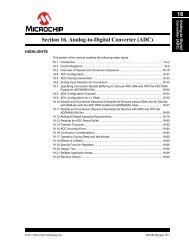
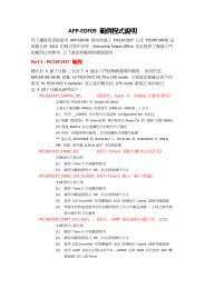
Figure 5-1 illustrates how the <strong>Flash</strong> program memory is addressed using the table instructions.<br />
A 24-bit program memory address is formed using bits of the TBLPAG register and the<br />
effective address (EA) from a W register specified in the table instruction. The 24-bit program<br />
counter (PC) is illustrated in Figure 5-1 for reference. The upper 23 bits of the EA are used to<br />
select the <strong>Flash</strong> program memory location.<br />
DS70609C-page 5-2<br />
© 2009-2011 <strong>Microchip</strong> Technology Inc.
<strong>Section</strong> <strong>5.</strong> <strong>Flash</strong> <strong>Programming</strong><br />
For the Byte mode table instructions, the LSb of the W register EA is used to select which byte<br />
of the 16-bit <strong>Flash</strong> program memory word is addressed. ‘1’ selects bits and ‘0’ selects<br />
bits . The LSb of the W register EA is ignored for a table instruction in Word mode.<br />
In addition to the <strong>Flash</strong> program memory address, the table instruction also specifies a W register<br />
(or a W Register Pointer to a memory location), that is the source of the <strong>Flash</strong> program memory<br />
data to be written or the destination for a <strong>Flash</strong> program memory read. For a table write operation<br />
in Byte mode, bits of the source working register are ignored.<br />
Figure 5-1:<br />
Addressing for Table Instructions<br />
Using<br />
Program<br />
Counter<br />
24 bits<br />
0 Program Counter<br />
1<br />
Using<br />
Table<br />
Instruction<br />
1/0<br />
TBLPAG Reg<br />
Working Reg EA<br />
8 bits 16 bits<br />
User/Configuration<br />
Space Select<br />
24-bit EA<br />
Byte<br />
Select<br />
<strong>5.</strong>2.1 Using Table Read Instructions<br />
Table reads require two steps:<br />
1. The address pointer is set up using the TBLPAG register and one of the W registers.<br />
2. The <strong>Flash</strong> program memory contents at the address location may be read.<br />
<strong>5.</strong>2.1.1 READ WORD MODE<br />
The code shown in Example 5-1, shows how to read a word of <strong>Flash</strong> program memory using the<br />
table instructions in Word mode.<br />
Example 5-1: Read Word Mode<br />
; Set up the address pointer to program space<br />
MOV #tblpage(PROG_ADDR),W0 ; get table page value<br />
MOV W0,TBLPAG ; load TBLPAG register<br />
MOV #tbloffset(PROG_ADDR),W0 ; load address LS word<br />
; Read the program memory location<br />
TBLRDH [W0],W3 ; Read high byte to W3<br />
TBLRDL [W0],W4 ; Read low word to W4<br />
5<br />
<strong>Flash</strong><br />
<strong>Programming</strong><br />
© 2009-2011 <strong>Microchip</strong> Technology Inc. DS70609C-page 5-3
dsPIC33E/PIC24E Family Reference Manual<br />
<strong>5.</strong>2.1.2 READ BYTE MODE<br />
The code shown in Example 5-2, shows the post-increment operator on the read of the low byte,<br />
which causes the address in the working register to increment by one. This sets EA to a ‘1’<br />
for access to the middle byte in the third write instruction. The last post-increment sets W0 back<br />
to an even address, pointing to the next <strong>Flash</strong> program memory location.<br />
Example 5-2: Read Byte Mode<br />
; Set up the address pointer to program space<br />
MOV #tblpage(PROG_ADDR),W0 ; get table page value<br />
MOV W0,TBLPAG ; load TBLPAG register<br />
MOV #tbloffset(PROG_ADDR),W0 ; load address LS word<br />
; Read the program memory location<br />
TBLRDH.B [W0],W3 ; Read high byte to W3<br />
TBLRDL.B [W0++],W4 ; Read low byte to W4<br />
TBLRDL.B [W0++],W5 ; Read middle byte to W5<br />
<strong>5.</strong>2.1.3 TABLE WRITE HOLDING LATCHES<br />
Table write instructions do not write directly to the nonvolatile program. Instead, the table write<br />
instructions load holding latches that store the write data. The NVM address registers must be<br />
loaded with the page address where latched data should be written. When all of the holding<br />
latches have been loaded, the actual memory programming operation is started by executing a<br />
special sequence of instructions.<br />
The dsPIC33E/PIC24E <strong>Flash</strong> program memory is segmented into pages (1024 instruction<br />
words) and rows (128 instruction words).<br />
The dsPIC33E/PIC24E family of devices support 128 holding registers to program one row of<br />
memory at a time. The memory logic automatically decides which set of write latches to load<br />
based on the address value of the NVM address registers. Refer to the specific device data sheet<br />
for more information.<br />
DS70609C-page 5-4<br />
© 2009-2011 <strong>Microchip</strong> Technology Inc.
<strong>Section</strong> <strong>5.</strong> <strong>Flash</strong> <strong>Programming</strong><br />
<strong>5.</strong>3 CONTROL REGISTERS<br />
Several Special Function Registers (SFRs) are used to program the <strong>Flash</strong> program memory<br />
erase and write operations: NVMCON, NVMKEY and the NVM Address registers, NVMADR and<br />
NVMADRU.<br />
<strong>5.</strong>3.1 NVMCON Register<br />
The NVMCON register is the primary control register for <strong>Flash</strong> and program/erase operations.<br />
This register selects whether an erase or program operation will be performed and can start the<br />
program or erase cycle.<br />
The NVMCON register is shown in Register 5-1. The lower byte of NVMCON configures the type<br />
of NVM operation that will be performed.<br />
<strong>5.</strong>3.2 NVMKEY Register<br />
The NVMKEY register (see Register 5-4) is a write-only register used to prevent accidental writes<br />
or erasures of the <strong>Flash</strong> memory. To start a programming or erase sequence, the following steps<br />
must be considered:<br />
1. Write 0x55 to NVMKEY.<br />
2. Write 0xAA to NVMKEY.<br />
3. Execute two NOP instructions.<br />
After this sequence, a write will be allowed to the NVMCON register for one instruction cycle. In<br />
most cases, the user application needs to set the WR bit (NVMCOM) to start the program<br />
or erase cycle. Interrupts should be disabled during the unlock sequence. Example 5-3 shows<br />
how the unlock sequence is performed.<br />
Example 5-3: NVMKEY Unlock Sequence<br />
; PUSH SR ; Disable interrupts, if enabled<br />
MOV #0x00E0,W0<br />
IOR SR<br />
MOV #0x55,W0<br />
MOV W0, NVMKEY<br />
MOV #0xAA,W0<br />
MOV W0, NVMKEY ; NOP not required<br />
BSET NVMCON,#15 ; Start the program/erase cycle<br />
NOP<br />
NOP<br />
POP SR ; Re-enable interrupts<br />
Refer to <strong>5.</strong>4.2 “<strong>Flash</strong> <strong>Programming</strong> Operations” for more programming examples.<br />
<strong>5.</strong>3.3 NVM Address Registers<br />
The two NVM Address registers, NVMADRU and NVMADR, when concatenated, form the 24-bit<br />
EA of the selected row or word for programming operations. The NVMADRU register is used to<br />
hold the upper eight bits of the EA, and the NVMADR register is used to hold the lower 16 bits of<br />
the EA.<br />
5<br />
<strong>Flash</strong><br />
<strong>Programming</strong><br />
© 2009-2011 <strong>Microchip</strong> Technology Inc. DS70609C-page 5-5
dsPIC33E/PIC24E Family Reference Manual<br />
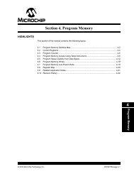
Register 5-1:<br />
NVMCON: <strong>Flash</strong> Memory Control Register<br />
R/SO-0 R/W-0 R/W-0 R/W-0 U-0 U-0 U-0 U-0<br />
WR (1) WREN (1) WRERR (1) NVMSIDL (2) — — — —<br />
bit 15 bit 8<br />
U-0 U-0 U-0 U-0 R/W-0 R/W-0 R/W-0 R/W-0<br />
— — — — NVMOP (3,5)<br />
bit 7 bit 0<br />
Legend:<br />
SO = Settable-only bit<br />
R = Readable bit W = Writable bit U = Unimplemented bit, read as ‘0’<br />
-n = Value at POR ‘1’ = Bit is set ‘0’ = Bit is cleared x = Bit is unknown<br />
bit 15 WR: Write Control bit (1)<br />
1 = Initiates a <strong>Flash</strong> program memory or erase operation. The operation is self-timed and the bit is<br />
cleared by hardware once operation is complete<br />
0 = Program or erase operation is complete and inactive<br />
bit 14 WREN: Write Enable bit (1)<br />
1 = Enable <strong>Flash</strong> program memory/erase operations<br />
0 = Inhibit <strong>Flash</strong> program memory/erase operations<br />
bit 13 WRERR: Write Sequence Error Flag bit (1)<br />
1 = An improper program or erase sequence attempt or termination has occurred (bit is set<br />
automatically on any set attempt of the WR bit)<br />
0 = The program or erase operation completed normally<br />
bit 12 NVMSIDL: Stop in Idle Mode bit (2)<br />
1 = Discontinue Primary and Auxiliary <strong>Flash</strong> operation when the device enters Idle mode<br />
0 = Continue Primary and Auxiliary <strong>Flash</strong> operation when the device enters Idle mode<br />
bit 11-4 Unimplemented: Read as ‘0’<br />
bit 3-0 NVMOP: NVM Operation Select bits (1,3,5)<br />
1111 = Reserved<br />
1110 = Reserved<br />
1101 = Bulk erase primary <strong>Flash</strong> program memory<br />
1100 = Reserved (4)<br />
1011 = Reserved (4)<br />
1010 = Bulk erase auxiliary <strong>Flash</strong> program memory<br />
0011 = Memory page erase operation<br />
0010 = Memory row program operation<br />
0001 = Memory word program operation (6)<br />
0000 = Program a single Configuration register byte<br />
Note 1: These bits can only be reset on POR.<br />
2: When exiting Idle mode, there is a power-up delay (TNPD) before <strong>Flash</strong> program memory becomes<br />
operational. Refer to the specific device data sheet for more information.<br />
3: All other combinations of NVMOP are unimplemented.<br />
4: Entire segment is erased with the exception of IVT.<br />
5: Execution of PWRSAV instruction is ignored while any of the NVM operations are in progress.<br />
6: The Word <strong>Programming</strong> RTSP operation causes two adjacent words (an even/odd instruction pair) to be<br />
reprogrammed.<br />
DS70609C-page 5-6<br />
© 2009-2011 <strong>Microchip</strong> Technology Inc.
<strong>Section</strong> <strong>5.</strong> <strong>Flash</strong> <strong>Programming</strong><br />
Register 5-2:<br />
NVMADRU: Nonvolatile Memory Upper Address Register<br />
U-0 U-0 U-0 U-0 U-0 U-0 U-0 U-0<br />
— — — — — — — —<br />
bit 15 bit 8<br />
R/W-x R/W-x R/W-x R/W-x R/W-x R/W-x R/W-x R/W-x<br />
NVMADRU<br />
bit 7 bit 0<br />
Legend:<br />
R = Readable bit W = Writable bit U = Unimplemented bit, read as ‘0’<br />
-n = Value at POR ‘1’ = Bit is set ‘0’ = Bit is cleared x = Bit is unknown<br />
bit 15-8 Unimplemented: Read as ‘0’<br />
bit 7-0 NVMADRU: Nonvolatile Memory Upper Write Address bits<br />
Selects the upper eight bits of the location to program or erase in <strong>Flash</strong> program memory. This register<br />
may be read or written by the user application.<br />
Register 5-3:<br />
NVMADR: Nonvolatile Memory Address Register<br />
R/W-x R/W-x R/W-x R/W-x R/W-x R/W-x R/W-x R/W-x<br />
NVMADR<br />
bit 15 bit 8<br />
R/W-x R/W-x R/W-x R/W-x R/W-x R/W-x R/W-x R/W-x<br />
NVMADR<br />
bit 7 bit 0<br />
Legend:<br />
R = Readable bit W = Writable bit U = Unimplemented bit, read as ‘0’<br />
-n = Value at POR ‘1’ = Bit is set ‘0’ = Bit is cleared x = Bit is unknown<br />
bit 15-0<br />
NVMADR: Nonvolatile Memory Write Address bits<br />
Selects the 16-bit offset of the location to program or erase in <strong>Flash</strong> program memory. This register<br />
may be read or written by the user application.<br />
Register 5-4: NVMKEY: Nonvolatile Memory Key Register<br />
U-0 U-0 U-0 U-0 U-0 U-0 U-0 U-0<br />
— — — — — — — —<br />
bit 15 bit 8<br />
W-0 W-0 W-0 W-0 W-0 W-0 W-0 W-0<br />
NVMKEY<br />
bit 7 bit 0<br />
5<br />
Legend:<br />
SO = Settable-only bit<br />
R = Readable bit W = Writable bit U = Unimplemented bit, read as ‘0’<br />
-n = Value at POR ‘1’ = Bit is set ‘0’ = Bit is cleared x = Bit is unknown<br />
bit 15-8 Unimplemented: Read as ‘0’<br />
bit 7-0 NVMKEY: Key Register (write-only) bits<br />
<strong>Flash</strong><br />
<strong>Programming</strong><br />
© 2009-2011 <strong>Microchip</strong> Technology Inc. DS70609C-page 5-7
dsPIC33E/PIC24E Family Reference Manual<br />
<strong>5.</strong>4 RUN-TIME SELF-PROGRAMMING (RTSP)<br />
RTSP allows the user application to modify <strong>Flash</strong> program memory contents. RTSP is<br />
accomplished using the TBLRD (table read) and TBLWT (table write) instructions, and the NVM<br />
Control registers. With RTSP, the user application can erase eight rows (128 * 8 = 1024<br />
instructions) of <strong>Flash</strong> program memory at a time and can write to the <strong>Flash</strong> program memory data<br />
a single row (128 instructions) at a time.<br />
<strong>5.</strong>4.1 RTSP Operation<br />
The dsPIC33E/PIC24E <strong>Flash</strong> program memory array is organized into rows of 128 instructions<br />
or 384 bytes. RTSP allows the user application to erase blocks of eight rows (1024 instructions)<br />
at a time and to program 128 instructions at a time. The 8-row erase blocks and single-row write<br />
blocks are edge-aligned, from the beginning of <strong>Flash</strong> program memory, on boundaries of<br />
3072 bytes and 384 bytes, respectively.<br />
The <strong>Flash</strong> program memory implements holding buffers that can contain 128 instructions of<br />
programming data. Prior to the actual programming operation, the write data must be loaded into<br />
the buffers in sequential order. The instruction words loaded must always be from a group of 128<br />
boundaries.<br />
The basic sequence for RTSP is to set up a Table Pointer, and then perform a series of TBLWT<br />
instructions to load the buffers. <strong>Programming</strong> is performed by setting the control bits in the<br />
NVMCON register. A total of 128 TBLWTL and TBLWTH instructions are required to load the<br />
instructions.<br />
Since only the buffers are written, all of the table write operations are single-word writes (two<br />
instruction cycles). A programming cycle is required for programming each row.<br />
When creating applications for the dsPIC33E/PIC24E devices, users should always specifically<br />
allocate the location of the <strong>Flash</strong> Configuration Word for configuration data in their code for the<br />
compiler. This ensures that the program code is not stored in this address when the code is<br />
compiled. The upper byte of all <strong>Flash</strong> Configuration Words in program memory should always be<br />
‘1111 1111’, which causes them to appear to be NOP instructions in the remote event that their<br />
locations are executed by accident. Since Configuration bits are not implemented in the<br />
corresponding locations, writing ‘1’s to these locations has no effect on device operation.<br />
Note:<br />
Performing a page erase operation on the last page of program memory clears the<br />
<strong>Flash</strong> Configuration Words, which enables code protection as a result. Therefore,<br />
users should avoid performing page erase operations on the last page of program<br />
memory.<br />
<strong>5.</strong>4.2 <strong>Flash</strong> <strong>Programming</strong> Operations<br />
A program or erase operation is necessary for programming or erasing the internal <strong>Flash</strong><br />
program memory in RTSP mode. The program or erase operation is automatically timed by the<br />
device (refer to the specific device data sheet for timing information). Setting the WR bit<br />
(NVMCON) starts the operation. The WR bit is automatically cleared when the operation is<br />
finished. In addition, the dsPIC33E/PIC24E device provides an NVM interrupt, which indicates<br />
when programming operation has completed.<br />
The CPU stalls until the programming operation is finished. The CPU will not execute any<br />
instructions or respond to interrupts during this time. If any interrupts occur during the<br />
programming cycle, they will remain pending until the cycle completes.<br />
DS70609C-page 5-8<br />
© 2009-2011 <strong>Microchip</strong> Technology Inc.
<strong>Section</strong> <strong>5.</strong> <strong>Flash</strong> <strong>Programming</strong><br />
Some dsPIC33E/PIC24E devices may provide auxiliary <strong>Flash</strong> program memory (refer to the<br />
specific device data sheet for details), which allows instruction execution without CPU stalls while<br />
user <strong>Flash</strong> program memory is being erased and/or programmed. Conversely, auxiliary <strong>Flash</strong><br />
program memory can be programmed without CPU stall, as long as code is executed from the<br />
user <strong>Flash</strong> program memory.<br />
Note 1: If a POR or BOR event occurs while an RTSP erase or programming operation is<br />
in progress, the RTSP operation is aborted immediately. The user should execute<br />
the RTSP operation again after the device comes out of reset.<br />
2: If an EXTR, SWR, WDTO, TRAPR, CM, or IOPUWR reset event occurs while an<br />
RTSP erase or programming operation is in progress, the device will be reset only<br />
after the RTSP operation is complete.<br />
3: If the <strong>Flash</strong> Configuration Words are reprogrammed, a reset sequence must be<br />
executed for the new values to be effective.<br />
<strong>5.</strong>4.2.1 FLASH ROW PROGRAMMING ALGORITHM<br />
The user application can program one row of <strong>Flash</strong> program memory (128 instruction words). To<br />
perform this, it is necessary to erase a page (1024 instruction words) containing the desired row.<br />
The general process is as follows:<br />
1. Read one page (1024 instruction words) of <strong>Flash</strong> program memory and store it into data<br />
RAM as a data “image”. The RAM image must be read from an even 1024-word program<br />
memory address boundary.<br />
2. Update the RAM data image with the new <strong>Flash</strong> program memory data.<br />
3. Erase the <strong>Flash</strong> program memory page.<br />
a) Set up the NVMCON register to erase one page of <strong>Flash</strong> program memory.<br />
b) Disable interrupts.<br />
c) Write the address of the row to be erased into the NVMADRU and NMVADR registers<br />
(can be any address within the row).<br />
d) Write the key sequence to the NVMKEY register to enable the erase.<br />
e) Set the WR bit (NVMCON). This will start the erase cycle.<br />
f) The WR bit is cleared when the erase cycle ends.<br />
g) Re-enable interrupts.<br />
4. Load the row (128 instruction words) of instruction words from RAM into the write latches<br />
using a table write operation.<br />
<strong>5.</strong> Program the row (128 instruction words) in <strong>Flash</strong> program memory.<br />
a) Set up the NVMCON register to program one row of <strong>Flash</strong> program memory.<br />
b) Disable interrupts.<br />
c) Write the address of the row to be programmed into the NVMADRU and NVMADR<br />
registers (can be any address within the row).<br />
d) Write the key sequence to the NVMKEY register to enable the program cycle.<br />
e) Set the WR bit. This will start the program cycle.<br />
f) The WR bit is cleared by the hardware when the program cycle ends.<br />
g) Re-enable interrupts.<br />
6. Repeat steps 4 through 6 to program all eight rows in the program memory page.<br />
7. Repeat steps 1 through 7, as needed, to program the desired amount of <strong>Flash</strong> program<br />
memory.<br />
Note 1: The user should remember that the minimum amount of <strong>Flash</strong> program memory<br />
that can be erased using RTSP is 1024 instruction word locations. Therefore, it is<br />
important that an image of these locations be stored in general purpose RAM<br />
before an erase cycle is initiated.<br />
2: A row or word in <strong>Flash</strong> program memory should not be programmed more than<br />
twice before being erased.<br />
3: In some devices, Configuration registers are part of the user space in the <strong>Flash</strong><br />
program memory. Therefore, the user is responsible for the operation to erase and<br />
row program on the last page.<br />
5<br />
<strong>Flash</strong><br />
<strong>Programming</strong><br />
© 2009-2011 <strong>Microchip</strong> Technology Inc. DS70609C-page 5-9
dsPIC33E/PIC24E Family Reference Manual<br />
<strong>5.</strong>4.2.2 ERASING ONE PAGE OF FLASH<br />
The code sequence shown in Example 5-4 can be used to erase a page (1024 instructions) of<br />
<strong>Flash</strong> program memory. The NVMCON register is configured to erase one page of program<br />
memory. The NVMADR and NMVADRU registers are loaded with the address of the page to be<br />
erased. The program memory must be erased at an “even” 1024 instruction word address<br />
boundary. Therefore, the 11 LSbs of the table write program memory address have no effect<br />
when a page is erased.<br />
The erase operation is initiated by writing a special unlock, or key sequence to the NVMKEY<br />
register before setting the WR bit (NVMCON). The unlock sequence needs to be executed<br />
in the exact order, as shown in Example 5-4, without interruption. Therefore, interrupts should be<br />
disabled prior to writing the sequence.<br />
Two NOP instructions should be inserted in the code after the erase cycle. Finally, interrupts can<br />
be enabled (if required).<br />
Example 5-4: Erasing a Page of <strong>Flash</strong> Program Memory<br />
; Define the start address from where the erase has to start<br />
.equ PROG_ADDR, 0x022222<br />
; Perform dummy table write to the Page to be erased.<br />
MOV #tblpage(PROG_ADDR),W0<br />
MOV W0,NVMADRU<br />
MOV #tbloffset(PROG_ADDR),W0<br />
MOV W0,NVMADR<br />
TBLWTL w0,[w0]<br />
; Setup NVMCON to erase one row of Program Memory<br />
MOV #0x4003,W0<br />
MOV W0,NVMCON<br />
; Disable interrupts while the KEY sequence is written<br />
PUSH SR<br />
MOV #0x00E0,W0<br />
IOR SR<br />
; Write the KEY Sequence<br />
MOV #0x55,W0<br />
MOV W0,NVMKEY<br />
MOV #0xAA,W0<br />
MOV W0,NVMKEY<br />
; Start the erase operation<br />
BSET NVMCON,#15<br />
; Insert two NOPs after the erase cycle (required)<br />
NOP<br />
NOP<br />
;Re-enable interrupts, if needed<br />
POP SR<br />
Note:<br />
Some device families have 512 instructions per page. Refer to the specific device<br />
data sheet to confirm the <strong>Flash</strong> page size.<br />
DS70609C-page 5-10<br />
© 2009-2011 <strong>Microchip</strong> Technology Inc.
<strong>Section</strong> <strong>5.</strong> <strong>Flash</strong> <strong>Programming</strong><br />
<strong>5.</strong>4.2.3 LOADING WRITE LATCHES<br />
The write latches are used as a storage mechanism between the user application table writes<br />
and the actual row programming sequence. Example 5-5 shows the sequence of instructions<br />
that can be used to load 128 write latches (128 instruction words). 128 TBLWTL and 128 TBLWTH<br />
instructions are needed to load the write latches for programming a row of <strong>Flash</strong> program<br />
memory.<br />
The row of 128 instruction words does not necessarily have to be written in sequential order.<br />
The 8 LSbs of the table write address determine which of the latches will be written. However,<br />
all 128 instruction words should be written for each programming cycle in order to overwrite old<br />
data.<br />
The <strong>Flash</strong> program memory must be programmed at an “even” 128 instruction word address<br />
boundary. In effect, the 8 LSbs of the table write operation select the write latches to program the<br />
instruction word within the row. They have no effect when a row is programmed.<br />
Note 1:<br />
The code for Load_Write_Latch_Row is shown in Example 5-5 and the code for<br />
Load_Write_Latch_Word is shown in Example 5-6. The code in both of these<br />
examples is referred to in subsequent examples.<br />
2: Refer to the specific device data sheet for the number of latches.<br />
Example 5-5: Loading Write Latches for Row <strong>Programming</strong><br />
Load_Write_Latch_Row:<br />
; Set up a pointer to the first latch location to be written.<br />
MOV #0xFA,W0<br />
MOV W0,TBLPAG<br />
MOV #0,W1<br />
; Perform the TBLWT instructions to write the latches<br />
; W2 is incremented in the TBLWTH instruction to point to the<br />
; next instruction location.<br />
MOV #128,W3<br />
loop:<br />
TBLWTL.b<br />
TBLWTL.b<br />
TBLWTH.b<br />
INC2<br />
DEC<br />
BRA<br />
[W2++], [W1++]<br />
[W2++], [W1--]<br />
[W2++], [W1]<br />
W1, W1<br />
W3, W3<br />
NZ, loop<br />
Example 5-6: Loading Write Latches for Word <strong>Programming</strong><br />
Load_Write_Latch_Word:<br />
; Define the start address from where the programming has to start<br />
.equ PROG_ADDR, 0x022222<br />
; Set up a pointer to the first latch location to be written.<br />
MOV #0xFA,W0<br />
MOV W0,TBLPAG<br />
MOV #0,W1<br />
; Perform the TBLWT instructions to write the latches<br />
TBLWTL [W2++],[W1]<br />
TBLWTH [W2++],[W1++]<br />
TBLWTL [W2++],[W1]<br />
TBLWTH [W2++],[W1++]<br />
5<br />
<strong>Flash</strong><br />
<strong>Programming</strong><br />
© 2009-2011 <strong>Microchip</strong> Technology Inc. DS70609C-page 5-11
dsPIC33E/PIC24E Family Reference Manual<br />
<strong>5.</strong>4.2.4 SINGLE ROW PROGRAMMING EXAMPLE<br />
The NVMCON register is configured to program one row of <strong>Flash</strong> program memory. The program<br />
operation is initiated by writing a special unlock, or key sequence to the NVMKEY register before<br />
setting the WR bit (NVMCON). The unlock sequence needs to be executed without<br />
interruption, and in the exact order, as shown in Example 5-7. Therefore, interrupts should be<br />
disabled prior to writing the sequence.<br />
Two NOP instructions should be inserted in the code after the programming cycle. Finally,<br />
interrupts can be enabled (if required).<br />
Example 5-7: Single Row <strong>Programming</strong><br />
; Define the start address from where the programming has to start<br />
.equ PROG_ADDR, 0x022222<br />
; Load the destination address to be written<br />
MOV #tblpage(PROG_ADDR),W9<br />
MOV #tbloffset(PROG_ADDR),W8<br />
MOV W9,NVMADRU<br />
MOV W8,NVMADR<br />
; Setup NVMCON to write 1 row of program memory<br />
MOV #0x4002,W0<br />
MOV W0,NVMCON<br />
; Load the 64 program memory write latches<br />
CALL Load_Write_Latch_Row<br />
; Disable interrupts, if enabled<br />
PUSH SR<br />
MOV #0x00E0,W0<br />
IOR SR<br />
; Write the KEY sequence<br />
MOV #0x55,W0<br />
MOV W0,NVMKEY<br />
MOV #0xAA,W0<br />
MOV W0,NVMKEY<br />
; Start the programming sequence<br />
BSET NVMCON,#15<br />
; Insert two NOPs after programming<br />
NOP<br />
NOP<br />
; Re-enable interrupts, if required<br />
POP SR<br />
Note:<br />
Refer to <strong>5.</strong>4.2.3 “Loading Write Latches” for additional information.<br />
DS70609C-page 5-12<br />
© 2009-2011 <strong>Microchip</strong> Technology Inc.
<strong>Section</strong> <strong>5.</strong> <strong>Flash</strong> <strong>Programming</strong><br />
<strong>5.</strong>4.2.5 WORD PROGRAMMING<br />
For users who are familiar with the dsPIC33F and PIC24H families of devices, where a single<br />
word is written into the write latch memory area, word programming for dsPIC33E/PIC24E<br />
devices is slightly different in that two words are programmed.<br />
Assuming the user application has erased the <strong>Flash</strong> location to be programmed, use table write<br />
instructions to write a pair of words into the first two word memory locations in the write latch<br />
memory area. Load the address of the word of <strong>Flash</strong> memory to be programmed into the NVM<br />
address registers.<br />
The NVMCON register is configured to program a pair of words of <strong>Flash</strong> program memory. The<br />
program operation is initiated by writing a special, unlock, or key sequence to the NVMKEY<br />
register before setting the WR bit (NVMCON). The unlock sequence needs to be executed<br />
in the exact order, as shown in Example 5-8, without interruption. Therefore, interrupts should be<br />
disabled prior to writing the sequence.<br />
Two NOP instructions should be inserted in the code after the programming cycle. Finally,<br />
interrupts can be enabled (if required).<br />
Example 5-8: <strong>Programming</strong> Two Words of <strong>Flash</strong> Memory<br />
; Define the start address from where the programming has to start<br />
.equ PROG_ADDR, 0x022222;<br />
Load the destination address to be written<br />
MOV #tblpage(PROG_ADDR),W9<br />
MOV #tbloffset(PROG_ADDR),W8<br />
MOV W9,NVMADRU<br />
MOV W8,NVMADR;<br />
; Load the two words into the latches<br />
CALL Load_Write_Latch_Word<br />
; Setup NVMCON for word programming<br />
MOV #0x4001,W0<br />
MOV W0,NVMCON<br />
; Disable interrupts while the KEY sequence is written<br />
PUSH SR<br />
MOV #0x00E0,W0<br />
IOR SR<br />
; Write the key sequence<br />
MOV #0x55,W0<br />
MOV W0,NVMKEY<br />
MOV #0xAA,W0<br />
MOV W0,NVMKEY<br />
; Start the write cycle<br />
BSET NVMCON,#15<br />
;Re-enable interrupts, if needed<br />
POP SR<br />
5<br />
<strong>Flash</strong><br />
<strong>Programming</strong><br />
© 2009-2011 <strong>Microchip</strong> Technology Inc. DS70609C-page 5-13
dsPIC33E/PIC24E Family Reference Manual<br />
<strong>5.</strong>4.3 Writing to Device Configuration Registers<br />
RTSP can be used to write to the device Configuration registers, and RTSP allows each<br />
Configuration register to be individually rewritten without first performing an erase cycle. Caution<br />
must be exercised when writing the Configuration registers since they control critical device<br />
operating parameters, such as the system clock source, PLL and WDT enable.<br />
The procedure for programming a device Configuration register is similar to the procedure for<br />
programming <strong>Flash</strong> program memory, except that only TBLWTL instructions are required. This is<br />
because the upper eight bits in each device Configuration register are unused. Furthermore,<br />
bit 23 of the table write address must be set to access the Configuration registers. Refer to<br />
<strong>Section</strong> 30. “Device Configuration” (DS70618) in the “dsPIC33E/PIC24E Family Reference<br />
Manual” and the specific device data sheet for a full description of the device Configuration<br />
registers.<br />
Note 1: Writing to device Configuration registers is not available in all devices. Refer to the<br />
specific device data sheet to determine the modes that are available according to<br />
the device-specific NVMOP bits definition.<br />
2: While performing RTSP on device Configuration registers, the device must be<br />
operating using the Internal FRC Oscillator (without PLL). If the device is operating<br />
from a different clock source, a clock switch to the Internal FRC Oscillator<br />
(NOSC = 000) must be performed prior to performing RTSP operation in the<br />
device Configuration registers.<br />
3: If the Primary Oscillator Mode Select bits (POSCMD) in the Oscillator<br />
Configuration register (FOSC) are being reprogrammed to a new value, the user<br />
must ensure that the Clock Switching Mode bits (FCKSM) in the FOSC<br />
register have an initial programmed value of ‘0’, prior to performing this RTSP<br />
operation.<br />
<strong>5.</strong>4.3.1 CONFIGURATION REGISTER WRITE ALGORITHM<br />
The general procedure is as follows:<br />
1. Store the value to be programmed into data RAM as data “image”.<br />
2. Write the new configuration value to the table write latch using a TBLWTL instruction.<br />
3. Configure NVMCON for a Configuration register write (NVMCON = 0x4000).<br />
4. Disable interrupts, if enabled.<br />
<strong>5.</strong> Write the address of the Configuration register to be programmed into the NVMADRU and<br />
NVMADR registers.<br />
6. Write the key sequence to the NVMKEY register.<br />
7. Start the write sequence by setting the WR bit (NVMCON).<br />
8. Re-enable interrupts, if needed.<br />
Example 5-9 shows the code sequence that can be used to modify a device Configuration<br />
register.<br />
DS70609C-page 5-14<br />
© 2009-2011 <strong>Microchip</strong> Technology Inc.
<strong>Section</strong> <strong>5.</strong> <strong>Flash</strong> <strong>Programming</strong><br />
Example 5-9: Configuration Register Write Code Example<br />
; Define the address to be written<br />
.equ DestinationAddress, 0x022222<br />
; Initialize the write pointer for writing to the latches<br />
MOV #0x0000, W7<br />
; Initialize TBLPAG register for writing to the latches<br />
MOV #0xFA, W12<br />
MOV W12, TBLPAG<br />
; Get the new data to write to the configuration register<br />
MOV #ConfigValue,W1<br />
; Perform the table write to load the write latch<br />
TBLWTL W1,[W7]<br />
; Load the address which is to be programmed<br />
MOV #DestinationAddress,W2<br />
MOV #DestinationAddress,W3<br />
MOV W3,NVMADRU<br />
MOV W2,NVMADR<br />
; Configure NVMCON for a configuration register write<br />
MOV #0x4000,W0<br />
MOV W0,NVMCON<br />
; Disable interrupts, if enabled<br />
PUSH SR<br />
MOV #0x00E0,W0<br />
IOR SR<br />
; Write the KEY sequence<br />
MOV #0x55,W0<br />
MOV W0,NVMKEY<br />
MOV #0xAA,W0<br />
MOV W0,NVMKEY<br />
; Start the programming sequence<br />
BSET NVMCON,#15<br />
; Insert two NOPs after programming<br />
NOP<br />
NOP<br />
; Re-enable interrupts, if required<br />
POP SR<br />
5<br />
<strong>Flash</strong><br />
<strong>Programming</strong><br />
© 2009-2011 <strong>Microchip</strong> Technology Inc. DS70609C-page 5-15
DS70609C-page 5-16 © 2009-2011 <strong>Microchip</strong> Technology Inc.<br />
<strong>5.</strong>5 REGISTER MAP<br />
Table 5-1:<br />
A summary of the registers associated with <strong>Flash</strong> <strong>Programming</strong> is provided in Table 5-1.<br />
<strong>Flash</strong> <strong>Programming</strong> Registers<br />
File Name Bit 15 Bit 14 Bit 13 Bit 12 Bit 11 Bit 10 Bit 9 Bit 8 Bit 7 Bit 6 Bit 5 Bit 4 Bit 3 Bit 2 Bit 1 Bit 0<br />
NVMCON WR WREN WRERR NVMSIDL — — — — — — — — NVMOP 0000<br />
NVMADRU — — — — — — — — NVMADRU 0000<br />
NVMADR NVMADR 0000<br />
NVMKEY — — — — — — — — NVMKEY 0000<br />
Legend: x = unknown value on Reset, — = unimplemented, read as ‘0’. Reset values are shown in hexadecimal.<br />
Note 1: Not all bits are available for all devices. Refer to the specific device data sheet for details.<br />
All<br />
Resets<br />
dsPIC33E/PIC24E Family Reference Manual
<strong>Section</strong> <strong>5.</strong> <strong>Flash</strong> <strong>Programming</strong><br />
<strong>5.</strong>6 RELATED APPLICATION NOTES<br />
This section lists application notes that are related to this section of the manual. These<br />
application notes may not be written specifically for the dsPIC33E/PIC24E product families, but<br />
the concepts are pertinent and could be used with modification and possible limitations. The<br />
current application notes related to <strong>Flash</strong> <strong>Programming</strong> are:<br />
Title Application Note #<br />
No related application notes at this time<br />
N/A<br />
Note:<br />
Please visit the <strong>Microchip</strong> web site (www.microchip.com) for additional Application<br />
Notes and code examples for the dsPIC33E/PIC24E family of devices.<br />
5<br />
<strong>Flash</strong><br />
<strong>Programming</strong><br />
© 2009-2011 <strong>Microchip</strong> Technology Inc. DS70609C-page 5-17
dsPIC33E/PIC24E Family Reference Manual<br />
<strong>5.</strong>7 REVISION HISTORY<br />
Revision A (August 2009)<br />
This is the initial released version of this document.<br />
Revision B (February 2011)<br />
This revision includes the following updates:<br />
• Examples:<br />
- Removed Example 5-3 and Example 5-4<br />
- Updated Example , Example 5-7 and Example 5-9<br />
- Any references to #WR were updated to #15 in Example , Example 5-7 and<br />
Example 5-8<br />
- Updated the following in Example 5-5:<br />
• Updated the title “Word <strong>Programming</strong>” to “Loading Write Latches for Row<br />
<strong>Programming</strong>”<br />
• Any reference to #ram_image was updated to #0xFA<br />
- Added Example 5-6<br />
- Updated the title in Example 5-8<br />
• Notes:<br />
- Added two notes in <strong>5.</strong>4.2 “<strong>Flash</strong> <strong>Programming</strong> Operations”<br />
- Updated the note in <strong>5.</strong>4.2.3 “Loading Write Latches”<br />
- Added three notes in <strong>5.</strong>4.3 “Writing to Device Configuration Registers”<br />
- Added Note 1 in Table 5-1<br />
• Registers:<br />
- Updated the bit values for NVMOP: NVM Operation Select bits in the <strong>Flash</strong><br />
Memory Control (NVMCON) register (see Register 5-1)<br />
• <strong>Section</strong>s:<br />
- Removed sections <strong>5.</strong>2.1.4 “Write Word Mode” and <strong>5.</strong>2.1.5 “Write Byte Mode”<br />
- Updated <strong>5.</strong>3 “Control Registers”<br />
- Updated the following in <strong>5.</strong>4.2.5 “Word <strong>Programming</strong>”:<br />
• Changed the section title “<strong>Programming</strong> One Word of <strong>Flash</strong> Memory“ to “Word<br />
<strong>Programming</strong>”<br />
• Updated the first paragraph<br />
• Changed the terms “one word“ to “a pair of words” in the second paragraph<br />
- Added a new Step 1 to <strong>5.</strong>4.3.1 “Configuration Register Write Algorithm”<br />
• Tables:<br />
- Updated Table 5-1<br />
• A few references to program memory were updated to <strong>Flash</strong> program memory<br />
• Other minor updates such as language and formatting updates were incorporated<br />
throughout the document<br />
DS70609C-page 5-18<br />
© 2009-2011 <strong>Microchip</strong> Technology Inc.
<strong>Section</strong> <strong>5.</strong> <strong>Flash</strong> <strong>Programming</strong><br />
Revision C (June 2011)<br />
This revision includes the following updates:<br />
• Examples:<br />
- Updated Example 5-4<br />
- Updated Example 5-8<br />
• Notes:<br />
- Added a note in <strong>5.</strong>4.1 “RTSP Operation”<br />
- Added Note 3 in <strong>5.</strong>4.2 “<strong>Flash</strong> <strong>Programming</strong> Operations”<br />
- Added Note 3 in <strong>5.</strong>4.2.1 “<strong>Flash</strong> Row <strong>Programming</strong> Algorithm”<br />
- Added a note in <strong>5.</strong>4.2.2 “Erasing One Page of <strong>Flash</strong>”<br />
- Added Note 2 in <strong>5.</strong>4.2.3 “Loading Write Latches”<br />
• Registers:<br />
- Updated the bit description for bits 15-0 in the Nonvolatile Memory Address register<br />
(see Register 5-3)<br />
• <strong>Section</strong>s:<br />
- Updated <strong>5.</strong>4.1 “RTSP Operation”<br />
- Updated <strong>5.</strong>4.2.5 “Word <strong>Programming</strong>”<br />
• Other minor updates such as language and formatting updates were incorporated<br />
throughout the document<br />
5<br />
<strong>Flash</strong><br />
<strong>Programming</strong><br />
© 2009-2011 <strong>Microchip</strong> Technology Inc. DS70609C-page 5-19
dsPIC33E/PIC24E Family Reference Manual<br />
NOTES:<br />
DS70609C-page 5-20<br />
© 2009-2011 <strong>Microchip</strong> Technology Inc.
Note the following details of the code protection feature on <strong>Microchip</strong> devices:<br />
• <strong>Microchip</strong> products meet the specification contained in their particular <strong>Microchip</strong> Data Sheet.<br />
• <strong>Microchip</strong> believes that its family of products is one of the most secure families of its kind on the market today, when used in the<br />
intended manner and under normal conditions.<br />
• There are dishonest and possibly illegal methods used to breach the code protection feature. All of these methods, to our<br />
knowledge, require using the <strong>Microchip</strong> products in a manner outside the operating specifications contained in <strong>Microchip</strong>’s Data<br />
Sheets. Most likely, the person doing so is engaged in theft of intellectual property.<br />
• <strong>Microchip</strong> is willing to work with the customer who is concerned about the integrity of their code.<br />
• Neither <strong>Microchip</strong> nor any other semiconductor manufacturer can guarantee the security of their code. Code protection does not<br />
mean that we are guaranteeing the product as “unbreakable.”<br />
Code protection is constantly evolving. We at <strong>Microchip</strong> are committed to continuously improving the code protection features of our<br />
products. Attempts to break <strong>Microchip</strong>’s code protection feature may be a violation of the Digital Millennium Copyright Act. If such acts<br />
allow unauthorized access to your software or other copyrighted work, you may have a right to sue for relief under that Act.<br />
Information contained in this publication regarding device<br />
applications and the like is provided only for your convenience<br />
and may be superseded by updates. It is your responsibility to<br />
ensure that your application meets with your specifications.<br />
MICROCHIP MAKES NO REPRESENTATIONS OR<br />
WARRANTIES OF ANY KIND WHETHER EXPRESS OR<br />
IMPLIED, WRITTEN OR ORAL, STATUTORY OR<br />
OTHERWISE, RELATED TO THE INFORMATION,<br />
INCLUDING BUT NOT LIMITED TO ITS CONDITION,<br />
QUALITY, PERFORMANCE, MERCHANTABILITY OR<br />
FITNESS FOR PURPOSE. <strong>Microchip</strong> disclaims all liability<br />
arising from this information and its use. Use of <strong>Microchip</strong><br />
devices in life support and/or safety applications is entirely at<br />
the buyer’s risk, and the buyer agrees to defend, indemnify and<br />
hold harmless <strong>Microchip</strong> from any and all damages, claims,<br />
suits, or expenses resulting from such use. No licenses are<br />
conveyed, implicitly or otherwise, under any <strong>Microchip</strong><br />
intellectual property rights.<br />
Trademarks<br />
The <strong>Microchip</strong> name and logo, the <strong>Microchip</strong> logo, dsPIC,<br />
KEELOQ, KEELOQ logo, MPLAB, PIC, PICmicro, PICSTART,<br />
PIC 32 logo, rfPIC and UNI/O are registered trademarks of<br />
<strong>Microchip</strong> Technology Incorporated in the U.S.A. and other<br />
countries.<br />
FilterLab, Hampshire, HI-TECH C, Linear Active Thermistor,<br />
MXDEV, MXLAB, SEEVAL and The Embedded Control<br />
Solutions Company are registered trademarks of <strong>Microchip</strong><br />
Technology Incorporated in the U.S.A.<br />
Analog-for-the-Digital Age, Application Maestro, chipKIT,<br />
chipKIT logo, CodeGuard, dsPICDEM, dsPICDEM.net,<br />
dsPICworks, dsSPEAK, ECAN, ECONOMONITOR,<br />
FanSense, HI-TIDE, In-Circuit Serial <strong>Programming</strong>, ICSP,<br />
Mindi, MiWi, MPASM, MPLAB Certified logo, MPLIB,<br />
MPLINK, mTouch, Omniscient Code Generation, PICC,<br />
PICC-18, PICDEM, PICDEM.net, PICkit, PICtail, REAL ICE,<br />
rfLAB, Select Mode, Total Endurance, TSHARC,<br />
UniWinDriver, WiperLock and ZENA are trademarks of<br />
<strong>Microchip</strong> Technology Incorporated in the U.S.A. and other<br />
countries.<br />
SQTP is a service mark of <strong>Microchip</strong> Technology Incorporated<br />
in the U.S.A.<br />
All other trademarks mentioned herein are property of their<br />
respective companies.<br />
© 2009-2011, <strong>Microchip</strong> Technology Incorporated, Printed in<br />
the U.S.A., All Rights Reserved.<br />
Printed on recycled paper.<br />
ISBN: 978-1-61341-317-3<br />
<strong>Microchip</strong> received ISO/TS-16949:2002 certification for its worldwide<br />
headquarters, design and wafer fabrication facilities in Chandler and<br />
Tempe, Arizona; Gresham, Oregon and design centers in California<br />
and India. The Company’s quality system processes and procedures<br />
are for its PIC ® MCUs and dsPIC ® DSCs, KEELOQ ® code hopping<br />
devices, Serial EEPROMs, microperipherals, nonvolatile memory and<br />
analog products. In addition, <strong>Microchip</strong>’s quality system for the design<br />
and manufacture of development systems is ISO 9001:2000 certified.<br />
© 2009-2011 <strong>Microchip</strong> Technology Inc. DS70609C-page 5 -21
Worldwide Sales and Service<br />
AMERICAS<br />
Corporate Office<br />
2355 West Chandler Blvd.<br />
Chandler, AZ 85224-6199<br />
Tel: 480-792-7200<br />
Fax: 480-792-7277<br />
Technical Support:<br />
http://www.microchip.com/<br />
support<br />
Web Address:<br />
www.microchip.com<br />
Atlanta<br />
Duluth, GA<br />
Tel: 678-957-9614<br />
Fax: 678-957-1455<br />
Boston<br />
Westborough, MA<br />
Tel: 774-760-0087<br />
Fax: 774-760-0088<br />
Chicago<br />
Itasca, IL<br />
Tel: 630-285-0071<br />
Fax: 630-285-0075<br />
Cleveland<br />
Independence, OH<br />
Tel: 216-447-0464<br />
Fax: 216-447-0643<br />
Dallas<br />
Addison, TX<br />
Tel: 972-818-7423<br />
Fax: 972-818-2924<br />
Detroit<br />
Farmington Hills, MI<br />
Tel: 248-538-2250<br />
Fax: 248-538-2260<br />
Indianapolis<br />
Noblesville, IN<br />
Tel: 317-773-8323<br />
Fax: 317-773-5453<br />
Los Angeles<br />
Mission Viejo, CA<br />
Tel: 949-462-9523<br />
Fax: 949-462-9608<br />
Santa Clara<br />
Santa Clara, CA<br />
Tel: 408-961-6444<br />
Fax: 408-961-6445<br />
Toronto<br />
Mississauga, Ontario,<br />
Canada<br />
Tel: 905-673-0699<br />
Fax: 905-673-6509<br />
ASIA/PACIFIC<br />
Asia Pacific Office<br />
Suites 3707-14, 37th Floor<br />
Tower 6, The Gateway<br />
Harbour City, Kowloon<br />
Hong Kong<br />
Tel: 852-2401-1200<br />
Fax: 852-2401-3431<br />
Australia - Sydney<br />
Tel: 61-2-9868-6733<br />
Fax: 61-2-9868-6755<br />
China - Beijing<br />
Tel: 86-10-8569-7000<br />
Fax: 86-10-8528-2104<br />
China - Chengdu<br />
Tel: 86-28-8665-5511<br />
Fax: 86-28-8665-7889<br />
China - Chongqing<br />
Tel: 86-23-8980-9588<br />
Fax: 86-23-8980-9500<br />
China - Hangzhou<br />
Tel: 86-571-2819-3180<br />
Fax: 86-571-2819-3189<br />
China - Hong Kong SAR<br />
Tel: 852-2401-1200<br />
Fax: 852-2401-3431<br />
China - Nanjing<br />
Tel: 86-25-8473-2460<br />
Fax: 86-25-8473-2470<br />
China - Qingdao<br />
Tel: 86-532-8502-7355<br />
Fax: 86-532-8502-7205<br />
China - Shanghai<br />
Tel: 86-21-5407-5533<br />
Fax: 86-21-5407-5066<br />
China - Shenyang<br />
Tel: 86-24-2334-2829<br />
Fax: 86-24-2334-2393<br />
China - Shenzhen<br />
Tel: 86-755-8203-2660<br />
Fax: 86-755-8203-1760<br />
China - Wuhan<br />
Tel: 86-27-5980-5300<br />
Fax: 86-27-5980-5118<br />
China - Xian<br />
Tel: 86-29-8833-7252<br />
Fax: 86-29-8833-7256<br />
China - Xiamen<br />
Tel: 86-592-2388138<br />
Fax: 86-592-2388130<br />
ASIA/PACIFIC<br />
India - Bangalore<br />
Tel: 91-80-3090-4444<br />
Fax: 91-80-3090-4123<br />
India - New Delhi<br />
Tel: 91-11-4160-8631<br />
Fax: 91-11-4160-8632<br />
India - Pune<br />
Tel: 91-20-2566-1512<br />
Fax: 91-20-2566-1513<br />
Japan - Yokohama<br />
Tel: 81-45-471- 6166<br />
Fax: 81-45-471-6122<br />
Korea - Daegu<br />
Tel: 82-53-744-4301<br />
Fax: 82-53-744-4302<br />
Korea - Seoul<br />
Tel: 82-2-554-7200<br />
Fax: 82-2-558-5932 or<br />
82-2-558-5934<br />
Malaysia - Kuala Lumpur<br />
Tel: 60-3-6201-9857<br />
Fax: 60-3-6201-9859<br />
Malaysia - Penang<br />
Tel: 60-4-227-8870<br />
Fax: 60-4-227-4068<br />
Philippines - Manila<br />
Tel: 63-2-634-9065<br />
Fax: 63-2-634-9069<br />
Singapore<br />
Tel: 65-6334-8870<br />
Fax: 65-6334-8850<br />
<strong>Taiwan</strong> - Hsin Chu<br />
Tel: 886-3-6578-300<br />
Fax: 886-3-6578-370<br />
<strong>Taiwan</strong> - Kaohsiung<br />
Tel: 886-7-213-7830<br />
Fax: 886-7-330-9305<br />
<strong>Taiwan</strong> - Taipei<br />
Tel: 886-2-2500-6610<br />
Fax: 886-2-2508-0102<br />
Thailand - Bangkok<br />
Tel: 66-2-694-1351<br />
Fax: 66-2-694-1350<br />
EUROPE<br />
Austria - Wels<br />
Tel: 43-7242-2244-39<br />
Fax: 43-7242-2244-393<br />
Denmark - Copenhagen<br />
Tel: 45-4450-2828<br />
Fax: 45-4485-2829<br />
France - Paris<br />
Tel: 33-1-69-53-63-20<br />
Fax: 33-1-69-30-90-79<br />
Germany - Munich<br />
Tel: 49-89-627-144-0<br />
Fax: 49-89-627-144-44<br />
Italy - Milan<br />
Tel: 39-0331-742611<br />
Fax: 39-0331-466781<br />
Netherlands - Drunen<br />
Tel: 31-416-690399<br />
Fax: 31-416-690340<br />
Spain - Madrid<br />
Tel: 34-91-708-08-90<br />
Fax: 34-91-708-08-91<br />
UK - Wokingham<br />
Tel: 44-118-921-5869<br />
Fax: 44-118-921-5820<br />
China - Zhuhai<br />
Tel: 86-756-3210040<br />
Fax: 86-756-3210049<br />
05/02/11<br />
DS70609C-page 5- 22<br />
© 2009-2011 <strong>Microchip</strong> Technology Inc.