dsPIC33F Family Reference Manual - Section 17. UART
dsPIC33F Family Reference Manual - Section 17. UART
dsPIC33F Family Reference Manual - Section 17. UART

You also want an ePaper? Increase the reach of your titles
YUMPU automatically turns print PDFs into web optimized ePapers that Google loves.
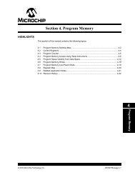
<strong>Section</strong> <strong>17.</strong> <strong>UART</strong><br />
HIGHLIGHTS<br />
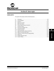
This section of the manual contains the following major topics:<br />
17<br />
<strong>17.</strong>1 Introduction ................................................................................................................17-2<br />
<strong>17.</strong>2 Control Registers........................................................................................................ 17-3<br />
<strong>17.</strong>3 <strong>UART</strong> Baud Rate Generator (BRG) ........................................................................... 17-9<br />
<strong>17.</strong>4 <strong>UART</strong> Configuration ................................................................................................. 17-11<br />
<strong>17.</strong>5 <strong>UART</strong> Transmitter..................................................................................................... 17-12<br />
<strong>17.</strong>6 <strong>UART</strong> Receiver ........................................................................................................ 17-17<br />
<strong>17.</strong>7 Using the <strong>UART</strong> for 9-Bit Communication................................................................ 17-21<br />
<strong>17.</strong>8 Receiving Break Characters..................................................................................... 17-23<br />
<strong>17.</strong>9 Other Features of the <strong>UART</strong> .................................................................................... 17-24<br />
<strong>17.</strong>10 <strong>UART</strong> Operation with DMA ...................................................................................... 17-26<br />
<strong>17.</strong>11 <strong>UART</strong> Operation During CPU Sleep and Idle Modes............................................... 17-29<br />
<strong>17.</strong>12 Operation of UxCTS and UxRTS Control Pins......................................................... 17-31<br />
<strong>17.</strong>13 Infrared Support ....................................................................................................... 17-33<br />
<strong>17.</strong>14 Registers Associated with the <strong>UART</strong> Module........................................................... 17-36<br />
<strong>17.</strong>15 Design Tips .............................................................................................................. 17-38<br />
<strong>17.</strong>16 Related Application Notes........................................................................................ 17-39<br />
<strong>17.</strong>17 Revision History ....................................................................................................... 17-40<br />
<strong>UART</strong><br />
© 2007 Microchip Technology Inc. DS70188B-page 17-1
<strong>dsPIC33F</strong> <strong>Family</strong> <strong>Reference</strong> <strong>Manual</strong><br />
<strong>17.</strong>1 INTRODUCTION<br />
The Universal Asynchronous Receiver Transmitter (<strong>UART</strong>) module is one of the serial I/O<br />
modules available in the <strong>dsPIC33F</strong> device family. The <strong>UART</strong> is a full-duplex, asynchronous<br />
communication channel that communicates with peripheral devices and personal computers<br />
using protocols such as RS-232, RS-485, LIN 1.2 and IrDA ® . The module also supports the<br />
hardware flow control option with UxCTS and UxRTS pins and includes the IrDA encoder and<br />
decoder.<br />
The primary features of the <strong>UART</strong> module are as follows:<br />
• Full-Duplex, 8- or 9-Bit Data Transmission through the UxTX and UxRX pins<br />
• Even, Odd or No Parity options (for 8-bit data)<br />
• One or two Stop bits<br />
• Hardware Auto-Baud feature<br />
• Hardware Flow Control option with UxCTS and UxRTS pins<br />
• Fully Integrated Baud Rate Generator with 16-Bit Prescaler<br />
• Baud Rates ranging from 10 Mbps to 38 bps at 40 MIPS<br />
• 4-deep First-In-First-Out (FIFO) Transmit Data Buffer<br />
• 4-deep FIFO Receive Data Buffer<br />
• Parity, Framing and Buffer Overrun Error Detection<br />
• Support for 9-bit mode with Address Detect (9th bit = 1)<br />
• Transmit and Receive Interrupts<br />
• Loopback mode for Diagnostic Support<br />
• IrDA Encoder and Decoder Logic<br />
• LIN 1.2 Protocol Support<br />
• 16x Baud Clock Output for External IrDA Encoder/Decoder support<br />
Note:<br />
Each <strong>dsPIC33F</strong> device variant may have one or more <strong>UART</strong> modules. An ‘x’ used<br />
in the names of pins, control/status bits and registers denotes the particular <strong>UART</strong><br />
module number. Refer to the specific device data sheets for more details.<br />
A simplified block diagram of the <strong>UART</strong> is shown in Figure 17-1. The <strong>UART</strong> module consists of<br />
the following key hardware elements:<br />
• Baud Rate Generator<br />
• Asynchronous Transmitter<br />
• Asynchronous Receiver<br />
Figure 17-1:<br />
<strong>UART</strong> Simplified Block Diagram<br />
Baud Rate Generator<br />
IrDA ®<br />
BCLKx<br />
Hardware Flow Control<br />
UxRTS<br />
UxCTS<br />
<strong>UART</strong>x Receiver<br />
UxRX<br />
<strong>UART</strong>x Transmitter<br />
UxTX<br />
DS70188B-page 17-2<br />
© 2007 Microchip Technology Inc.
<strong>17.</strong>2 CONTROL REGISTERS<br />
<strong>Section</strong> <strong>17.</strong> <strong>UART</strong><br />
21<br />
Register 17-1: UxMODE: <strong>UART</strong>x Mode Register<br />
R/W-0 R/W-0 R/W-0 R/W-0 R/W-0 R/W-0 R/W-0 R/W-0<br />
<strong>UART</strong>EN — USIDL IREN RTSMD — UEN<br />
bit 15 bit 8<br />
<strong>UART</strong><br />
R/W-0 R/W-0 R/W-0 R/W-0 R/W-0 R/W-0 R/W-0 R/W-0<br />
WAKE LPBACK ABAUD URXINV BRGH PDSEL STSEL<br />
bit 7 bit 0<br />
Legend:<br />
R = Readable bit W = Writable bit U = Unimplemented bit, read as ‘0’<br />
-n = Value at POR ‘1’ = Bit is set ‘0’ = Bit is cleared x = Bit is unknown<br />
bit 15<br />
bit 14<br />
bit 13<br />
<strong>UART</strong>EN: <strong>UART</strong>x Enable bit<br />
1 = <strong>UART</strong>x is enabled; <strong>UART</strong>x pins are controlled by <strong>UART</strong>x as defined by the UEN and<br />
UTXEN control bits<br />
0 = <strong>UART</strong>x is disabled; <strong>UART</strong>x pins are controlled by the corresponding PORT, LAT and TRIS bits<br />
Reserved<br />
USIDL: Stop in Idle Mode bit<br />
1 = Discontinue operation when the device enters Idle mode<br />
0 = Continue operation in Idle mode<br />
bit 12 IREN: IrDA Encoder and Decoder Enable bit (1)<br />
bit 11<br />
bit 10<br />
bit 9-8<br />
bit 7<br />
bit 6<br />
bit 5<br />
bit 4<br />
1 = IrDA encoder and decoder are enabled<br />
0 = IrDA encoder and decoder are disabled<br />
RTSMD: Mode Selection for UxRTS Pin bit<br />
1 = UxRTS is in Simplex mode<br />
0 = UxRTS is in Flow Control mode<br />
Reserved<br />
UEN: <strong>UART</strong>x Enable bits<br />
11 = UxTX, UxRX and BCLKx pins are enabled and used; UxCTS pin is controlled by port latches<br />
10 = UxTX, UxRX, UxCTS and UxRTS pins are enabled and used<br />
01 = UxTX, UxRX and UxRTS pins are enabled and used; UxCTS pin is controlled by port latches<br />
00 = UxTX and UxRX pins are enabled and used; UxCTS, UxRTS and BCLKx pins are controlled by<br />
port latches<br />
WAKE: Enable Wake-up on Start bit Detect During Sleep Mode bit<br />
1 = Wake-up is enabled<br />
0 = Wake-up is disabled<br />
LPBACK: <strong>UART</strong>x Loopback Mode Select bit<br />
1 = Enable Loopback mode<br />
0 = Loopback mode is disabled<br />
ABAUD: Auto-Baud Enable bit<br />
1 = Enable baud rate measurement on the next character. Requires reception of a Sync field (55h);<br />
cleared in hardware upon completion.<br />
0 = Baud rate measurement disabled or completed<br />
URXINV: Receive Polarity Inversion bit<br />
1 = UxRX Idle state is ‘0’<br />
0 = UxRX Idle state is ‘1’<br />
Note 1:<br />
This feature is only available for Low-speed mode (BRGH = 0). See device data sheet for details.<br />
© 2007 Microchip Technology Inc. DS70188B-page 17-3
<strong>dsPIC33F</strong> <strong>Family</strong> <strong>Reference</strong> <strong>Manual</strong><br />
Register 17-1:<br />
bit 3<br />
bit 2-1<br />
bit 0<br />
UxMODE: <strong>UART</strong>x Mode Register (Continued)<br />
BRGH: High Baud Rate Select bit<br />
1 = High speed<br />
0 = Low speed<br />
PDSEL: Parity and Data Selection bits<br />
11 = 9-bit data, no parity<br />
10 = 8-bit data, odd parity<br />
01 = 8-bit data, even parity<br />
00 = 8-bit data, no parity<br />
STSEL: Stop Selection bit<br />
1 = 2 Stop bits<br />
0 = 1 Stop bit<br />
Note 1:<br />
This feature is only available for Low-speed mode (BRGH = 0). See device data sheet for details.<br />
DS70188B-page 17-4<br />
© 2007 Microchip Technology Inc.
<strong>Section</strong> <strong>17.</strong> <strong>UART</strong><br />
21<br />
Register 17-2:<br />
UxSTA: <strong>UART</strong>x Status and Control Register<br />
R/W-0 R/W-0 R/W-0 U-0 R/W-0 R/W-0 R-0 R-1<br />
UTXISEL1 UTXINV UTXISEL0 — UTXBRK UTXEN UTXBF TRMT<br />
bit 15 bit 8<br />
<strong>UART</strong><br />
R/W-0 R/W-0 R/W-0 R-1 R-0 R-0 R/C-0 R-0<br />
URXISEL ADDEN RIDLE PERR FERR OERR URXDA<br />
bit 7 bit 0<br />
Legend:<br />
C = Clearable bit<br />
R = Readable bit W = Writable bit U = Unimplemented bit, read as ‘0’<br />
-n = Value at POR ‘1’ = Bit is set ‘0’ = Bit is cleared x = Bit is unknown<br />
bit 15,13<br />
UTXISEL Transmission Interrupt Mode Selection bits<br />
11 = Reserved<br />
10 = Interrupt generated when a character is transferred to the Transmit Shift register and the<br />
transmit buffer becomes empty<br />
01 = Interrupt generated when the last transmission is over (i.e., the last character has been shifted<br />
out of the Transmit Shift register) and all the transmit operations are completed<br />
00 = Interrupt generated when any character is transferred to the Transmit Shift Register (which<br />
implies at least one location is empty in the transmit buffer)<br />
bit 14 UTXINV: Transmit Polarity Inversion bit<br />
IREN = 0:<br />
1 = UxTX Idle state is ‘1’<br />
0 = UxTX Idle state is ‘0’<br />
IREN = 1:<br />
1 = IrDA encoded UxTX Idle state is ‘1’<br />
0 = IrDA encoded UxTX Idle state is ‘0’<br />
bit 12 Unimplemented: Read as ‘0’<br />
bit 11<br />
bit 10<br />
bit 9<br />
bit 8<br />
UTXBRK: Transmit Break bit<br />
1 = UxTX pin is driven low regardless of the transmitter state (Sync Break transmission – Start bit<br />
followed by twelve ‘0’s and a Stop bit)<br />
0 = Sync Break transmission is disabled or completed<br />
UTXEN: Transmit Enable bit<br />
1 = <strong>UART</strong>x transmitter enabled; UxTX pin is controlled by <strong>UART</strong>x (if <strong>UART</strong>EN = 1)<br />
0 = <strong>UART</strong>x transmitter disabled; any pending transmission is aborted and the buffer is reset; UxTX<br />
pin is controlled by PORT<br />
UTXBF: Transmit Buffer Full Status bit (read-only)<br />
1 = Transmit buffer is full<br />
0 = Transmit buffer is not full; at least one more data word can be written<br />
TRMT: Transmit Shift Register is Empty bit (read-only)<br />
1 = Transmit Shift register is empty and the transmit buffer is empty (i.e., the last transmission has<br />
completed)<br />
0 = Transmit Shift register is not empty; a transmission is in progress or queued in the transmit buffer<br />
bit 7-6 URXISEL: Receive Interrupt Mode Selection bits<br />
11 = Interrupt flag bit is set when the receive buffer is full (i.e., has 4 data characters)<br />
10 = Interrupt flag bit is set when the receive buffer is 3/4 full (i.e., has 3 data characters)<br />
0x = Interrupt flag bit is set when a character is received<br />
bit 5 ADDEN: Address Character Detect bit (bit 8 of received data = 1)<br />
1 = Address Detect mode enabled. If 9-bit mode is not selected, this control bit has no effect.<br />
0 = Address Detect mode disabled<br />
© 2007 Microchip Technology Inc. DS70188B-page 17-5
<strong>dsPIC33F</strong> <strong>Family</strong> <strong>Reference</strong> <strong>Manual</strong><br />
Register 17-2:<br />
bit 4<br />
bit 3<br />
bit 2<br />
bit 1<br />
bit 0<br />
UxSTA: <strong>UART</strong>x Status and Control Register (Continued)<br />
RIDLE: Receiver Idle bit (read-only)<br />
1 = Receiver is Idle<br />
0 = Data is being received<br />
PERR: Parity Error Status bit (read-only)<br />
1 = Parity error has been detected for the current character<br />
0 = Parity error has not been detected<br />
FERR: Framing Error Status bit (read-only)<br />
1 = Framing error has been detected for the current character<br />
0 = Framing error has not been detected<br />
OERR: Receive Buffer Overrun Error Status bit (clear/read-only)<br />
1 = Receive buffer has overflowed<br />
0 = Receive buffer has not overflowed. (Clearing a previously set OERR bit will reset the receiver<br />
buffer and RSR to an empty state.)<br />
URXDA: Receive Buffer Data Available bit (read-only)<br />
1 = Receive buffer has data; at least one more character can be read<br />
0 = Receive buffer is empty<br />
DS70188B-page 17-6<br />
© 2007 Microchip Technology Inc.
<strong>Section</strong> <strong>17.</strong> <strong>UART</strong><br />
21<br />
Register 17-3:<br />
UxRXREG: <strong>UART</strong>x Receive Register<br />
U-0 U-0 U-0 U-0 U-0 U-0 U-0 R-0<br />
— — — — — — — URX8<br />
bit 15 bit 8<br />
<strong>UART</strong><br />
R-0 R-0 R-0 R-0 R-0 R-0 R-0 R-0<br />
URX<br />
bit 7 bit 0<br />
Legend:<br />
R = Readable bit W = Writable bit U = Unimplemented bit, read as ‘0’<br />
-n = Value at POR ‘1’ = Bit is set ‘0’ = Bit is cleared x = Bit is unknown<br />
bit 15-9 Unimplemented: Read as ‘0’<br />
bit 8<br />
URX8: Data bit 8 of the Received Character (in 9-bit mode)<br />
bit 7-0 URX: Data bits 7-0 of the Received Character<br />
Register 17-4:<br />
UxTXREG: <strong>UART</strong>x Transmit Register (Write-Only)<br />
U-0 U-0 U-0 U-0 U-0 U-0 U-0 W-x<br />
— — — — — — — UTX8<br />
bit 15 bit 8<br />
W-x W-x W-x W-x W-x W-x W-x W-x<br />
UTX<br />
bit 7 bit 0<br />
Legend:<br />
R = Readable bit W = Writable bit U = Unimplemented bit, read as ‘0’<br />
-n = Value at POR ‘1’ = Bit is set ‘0’ = Bit is cleared x = Bit is unknown<br />
bit 15-9 Unimplemented: Read as ‘0’<br />
bit 8<br />
UTX8: Data bit 8 of the Transmitted Character (in 9-bit mode)<br />
bit 7-0 UTX: Data bits 7-0 of the Transmitted Character<br />
© 2007 Microchip Technology Inc. DS70188B-page 17-7
<strong>dsPIC33F</strong> <strong>Family</strong> <strong>Reference</strong> <strong>Manual</strong><br />
Register 17-5:<br />
UxBRG: <strong>UART</strong>x Baud Rate Register<br />
R/W-0 R/W-0 R/W-0 R/W-0 R/W-0 R/W-0 R/W-0 W-x<br />
BRG<br />
bit 15 bit 8<br />
R/W-0 R/W-0 R/W-0 R/W-0 R/W-0 R/W-0 R/W-0 R/W-0<br />
BRG<br />
bit 7 bit 0<br />
Legend:<br />
R = Readable bit W = Writable bit U = Unimplemented bit, read as ‘0’<br />
-n = Value at POR ‘1’ = Bit is set ‘0’ = Bit is cleared x = Bit is unknown<br />
bit 15-0<br />
BRG: Baud Rate Divisor bits<br />
DS70188B-page 17-8<br />
© 2007 Microchip Technology Inc.
<strong>17.</strong>3 <strong>UART</strong> BAUD RATE GENERATOR (BRG)<br />
<strong>Section</strong> <strong>17.</strong> <strong>UART</strong><br />
The <strong>UART</strong> module includes a dedicated 16-bit Baud Rate Generator. The UxBRG register controls<br />
the period of a free-running, 16-bit timer. Equation 17-1 shows the formula for computing<br />
the baud rate with BRGH = 0.<br />
Equation 17-1: <strong>UART</strong> Baud Rate with BRGH = 0<br />
21<br />
<strong>UART</strong><br />
Baud Rate =<br />
FCY<br />
16 × (UxBRG + 1)<br />
FCY<br />
UxBRG = – 1<br />
16 × Baud Rate<br />
Note:<br />
FCY denotes the instruction cycle clock frequency (FOSC/2).<br />
Example 17-1 shows the formula for calculating the baud rate error for the following conditions:<br />
• FCY = 4 MHz<br />
• Desired Baud Rate = 9600<br />
Example 17-1: Baud Rate Error Calculation (BRGH = 0)<br />
Desired Baud Rate = FCY/(16 (UxBRG + 1))<br />
Solving for UxBRG value:<br />
UxBRG = ( (FCY/Desired Baud Rate)/16) – 1<br />
UxBRG = ((4000000/9600)/16) – 1<br />
UxBRG = 25<br />
Calculated Baud Rate = 4000000/(16 (25 + 1))<br />
= 9615<br />
Error = (Calculated Baud Rate – Desired Baud Rate)<br />
Desired Baud Rate<br />
= (9615 – 9600)/9600<br />
= 0.16%<br />
The maximum baud rate (BRGH = 0) possible is FCY/16 (for UxBRG = 0), and the minimum baud<br />
rate possible is FCY/(16 * 65536).<br />
Equation 17-2 shows the formula for computing the baud rate with BRGH = 1.<br />
Equation 17-2: <strong>UART</strong> Baud Rate with BRGH = 1<br />
Baud Rate =<br />
FCY<br />
4 × (UxBRG + 1)<br />
FCY<br />
UxBRG = – 1<br />
4 × Baud Rate<br />
Note:<br />
FCY denotes the instruction cycle clock frequency.<br />
The maximum baud rate (BRGH = 1) possible is FCY/4 (for UxBRG = 0), and the minimum baud<br />
rate possible is FCY/(4 * 65536).<br />
Writing a new value to the UxBRG register causes the BRG timer to be reset (cleared). This<br />
ensures the BRG does not wait for a timer overflow before generating the new baud rate.<br />
© 2007 Microchip Technology Inc. DS70188B-page 17-9
<strong>dsPIC33F</strong> <strong>Family</strong> <strong>Reference</strong> <strong>Manual</strong><br />
<strong>17.</strong>3.1 BCLKx Output<br />
The BCLKx pin will output the 16x baud clock if the <strong>UART</strong> and BCLKx output are enabled<br />
(UEN = 11). This feature is used for external IrDA encoder/decoder support (refer to<br />
Figure 17-2). BCLKx output stays low during Sleep mode. BCLKx is forced as an output as long<br />
as the <strong>UART</strong> is kept in this mode (UEN = 11), without regard to the PORTx and TRISx latch<br />
bits.<br />
Figure 17-2:<br />
BCLKx Output vs. UxBRG Programming<br />
TCY<br />
BCLKx @ BRG = 0<br />
BCLKx @ BRG = 1<br />
BCLKx @ BRG = 2<br />
BCLKx @ BRG = 3<br />
BCLKx @ BRG = 4<br />
BCLKx @ BRG = N<br />
(N + 1)TCY<br />
UxTX<br />
DS70188B-page 17-10<br />
© 2007 Microchip Technology Inc.
<strong>17.</strong>4 <strong>UART</strong> CONFIGURATION<br />
<strong>Section</strong> <strong>17.</strong> <strong>UART</strong><br />
The <strong>UART</strong> uses standard Non-Return-to-Zero (NRZ) format (one Start bit, eight or nine data bits<br />
and one or two Stop bits). Parity is supported by the hardware and may be configured by the user<br />
as even, odd or no parity. The most common data format is 8 bits, no parity and one Stop bit<br />
(denoted as 8, N, 1), which is the default (POR) setting. The number of data bits and Stop bits<br />
and the parity are specified in the PDSEL (UxMODE) and STSEL (UxMODE)<br />
bits. An on-chip, dedicated, 16-bit Baud Rate Generator can be used to derive standard baud<br />
rate frequencies from the oscillator. The <strong>UART</strong> transmits and receives the LSb first. The <strong>UART</strong><br />
module’s transmitter and receiver are functionally independent but use the same data format and<br />
baud rate.<br />
21<br />
<strong>UART</strong><br />
<strong>17.</strong>4.1 Enabling the <strong>UART</strong><br />
The <strong>UART</strong> module is enabled by setting the <strong>UART</strong>EN (UxMODE) bit and UTXEN<br />
(UxSTA) bit. Once enabled, the UxTX and UxRX pins are configured as an output and an<br />
input, respectively, overriding the TRIS and PORT register bit settings for the corresponding I/O<br />
port pins. The UxTX pin is at logic ‘1’ when no transmission is taking place.<br />
Note:<br />
The UTXEN bit should not be set until the <strong>UART</strong>EN bit has been set; otherwise,<br />
<strong>UART</strong> transmissions will not be enabled.<br />
<strong>17.</strong>4.2 Disabling the <strong>UART</strong><br />
The <strong>UART</strong> module is disabled by clearing the <strong>UART</strong>EN (UxMODE) bit. This is the default<br />
state after any Reset. If the <strong>UART</strong> is disabled, all <strong>UART</strong> pins operate as port pins under the<br />
control of their corresponding PORT and TRIS bits.<br />
Disabling the <strong>UART</strong> module resets the buffers to empty states. Any data characters in the buffers<br />
are lost and the baud rate counter is reset.<br />
All error and status flags associated with the <strong>UART</strong> module are reset when the module is disabled.<br />
The URXDA, OERR, FERR, PERR, UTXEN, UTXBRK and UTXBF bits are cleared,<br />
whereas RIDLE and TRMT are set. Other control bits (including ADDEN, URXISEL and<br />
UTXISEL) and the UxMODE and UxBRG registers are not affected.<br />
Clearing the <strong>UART</strong>EN bit while the <strong>UART</strong> is active will abort all pending transmissions and receptions<br />
and reset the module as defined above. Re-enabling the <strong>UART</strong> will restart the <strong>UART</strong> in the<br />
same configuration.<br />
© 2007 Microchip Technology Inc. DS70188B-page 17-11
<strong>dsPIC33F</strong> <strong>Family</strong> <strong>Reference</strong> <strong>Manual</strong><br />
<strong>17.</strong>5 <strong>UART</strong> TRANSMITTER<br />
The <strong>UART</strong> transmitter block diagram is shown in Figure 17-3. The heart of the transmitter is the<br />
Transmit Shift register (UxTSR). The Shift register obtains its data from the transmit FIFO buffer,<br />
UxTXREG. The UxTXREG register is loaded with data in software. The UxTSR register is not<br />
loaded until the Stop bit has been transmitted from the previous load. As soon as the Stop bit is<br />
transmitted, the UxTSR is loaded with new data from the UxTXREG register (if available).<br />
Note:<br />
The UxTSR register is not mapped in data memory, so it is not available to the user.<br />
Figure 17-3:<br />
<strong>UART</strong> Transmitter Block Diagram<br />
16<br />
Internal Data Bus<br />
Word Write-Only<br />
Word<br />
or Byte<br />
Write<br />
UxMODE<br />
UxSTA<br />
15 9 8 7 0<br />
UTX8<br />
UxTXREG Low Byte<br />
Transmit Control<br />
Transmit FIFO<br />
– Control UxTSR<br />
– Control Buffer<br />
– Generate Flags<br />
– Generate Interrupt<br />
UTXBRK<br />
Load UxTSR<br />
UxTXIF<br />
UxTX<br />
UxTX<br />
Data<br />
(Start)<br />
(Stop)<br />
Parity<br />
Parity<br />
Generator<br />
Transmit Shift Register (UxTSR)<br />
÷ 16 Divider<br />
16x Baud Clock<br />
from Baud Rate<br />
Generator<br />
Control<br />
Signals<br />
UxCTS<br />
Note: ‘x’ denotes the <strong>UART</strong> number.<br />
Transmission is enabled by setting the UTXEN enable bit (UxSTA). The actual transmission<br />
will not occur until the UxTXREG register has been loaded with data and the Baud Rate<br />
Generator (UxBRG) has produced a shift clock (Figure 17-3). The transmission can also be<br />
started by first loading the UxTXREG register and then setting the UTXEN enable bit. Normally,<br />
when transmission is first started, the UxTSR register is empty, so a transfer to the UxTXREG<br />
register will result in an immediate transfer to UxTSR. Clearing the UTXEN bit during a<br />
transmission will cause the transmission to be aborted and will reset the transmitter. As a result,<br />
the UxTX pin will revert to a high-impedance state.<br />
In order to select 9-bit transmission, the PDSEL bits (UxMODE) should be set to ‘11’<br />
and the ninth bit should be written to the UTX8 bit (UxTXREG). A word write should be<br />
performed to UxTXREG so that all nine bits are written at the same time.<br />
Note:<br />
There is no parity in the case of a 9-bit data transmission.<br />
It is recommended to have a delay between enabling the <strong>UART</strong>x (<strong>UART</strong>EN = 1) and initiating the<br />
first transmission. The delay is baud rate dependent and should be equal to or longer than the<br />
time it takes to transmit one data bit.<br />
DS70188B-page 17-12<br />
© 2007 Microchip Technology Inc.
<strong>17.</strong>5.1 Transmit Buffer (UxTXREG)<br />
<strong>Section</strong> <strong>17.</strong> <strong>UART</strong><br />
The transmit buffer is 9 bits wide and 4 levels deep. Together with the Transmit Shift registers<br />
(UxTSR), the user effectively has a 5-level deep buffer. It is organized as First-In-First-Out<br />
(FIFO). Once the UxTXREG contents are transferred to the UxTSR register, the current buffer<br />
location becomes available for new data to be written and the next buffer location is sourced to<br />
the UxTSR register. The UTXBF (UxSTA) status bit is set whenever the buffer is full. If a user<br />
attempts to write to a full buffer, the new data will not be accepted into the FIFO.<br />
The FIFO is reset during any device Reset but is not affected when the device enters a<br />
Power-Saving mode or wakes up from a Power-Saving mode.<br />
<strong>17.</strong>5.2 Transmit Interrupt<br />
The Transmit Interrupt Flag (UxTXIF) is located in the corresponding Interrupt Flag Status (IFS)<br />
register. The UTXISEL control bits (UxSTA) determine when the <strong>UART</strong> will<br />
generate a transmit interrupt.<br />
1. If UTXISEL = 00, the UxTXIF is set when a character is transferred from the transmit<br />
buffer to the Transmit Shift register (UxTSR). This implies at least one location is empty in<br />
the transmit buffer.<br />
2. If UTXISEL = 01, the UxTXIF is set when the last character is shifted out of the<br />
Transmit Shift register (UxTSR). This implies that all the transmit operations are completed.<br />
3. If UTXISEL = 10, the UxTXIF is set when the character is transferred to the Transmit<br />
Shift register (UxTSR) and the transmit buffer is empty.<br />
The UxTXIF bit will be set when the module is first enabled. The user should clear the UxTXIF<br />
bit in the ISR.<br />
Switching between the two Interrupt modes during operation is possible.<br />
Note:<br />
When the UTXEN bit is set, the UxTXIF flag bit will also be set if<br />
UTXISEL = 00, since the transmit buffer is not yet full (can move transmit data<br />
to the UxTXREG register).<br />
While the UxTXIF flag bit indicates the status of the UxTXREG register, the TRMT bit<br />
(UxSTA) shows the status of the UxTSR. The TRMT status bit is a read-only bit which is set<br />
when the UxTSR is empty. No interrupt logic is tied to this bit, so the user has to poll this bit to<br />
determine if the UxTSR is empty.<br />
21<br />
<strong>UART</strong><br />
© 2007 Microchip Technology Inc. DS70188B-page 17-13
<strong>dsPIC33F</strong> <strong>Family</strong> <strong>Reference</strong> <strong>Manual</strong><br />
<strong>17.</strong>5.3 Setup for <strong>UART</strong> Transmit<br />
Use the following steps when setting up a transmission:<br />
1. Initialize the UxBRG register for the appropriate baud rate (see <strong>Section</strong> <strong>17.</strong>3 “<strong>UART</strong> Baud<br />
Rate Generator (BRG)”).<br />
2. Set the number of data bits, number of Stop bits and parity selection by writing to the<br />
PDSEL (UxMODE) and STSEL (UxMODE) bits.<br />
3. If transmit interrupts are desired, set the UxTXIE control bit in the corresponding Interrupt<br />
Enable Control register (IEC). Specify the interrupt priority for the transmit interrupt using the<br />
UxTXIP control bits in the corresponding Interrupt Priority Control register (IPC). Also,<br />
select the Transmit Interrupt mode by writing the UTXISEL (UxSTA) bits.<br />
4. Enable the <strong>UART</strong> module by setting the <strong>UART</strong>EN (UxMODE) bit.<br />
5. Enable the transmission by setting the UTXEN (UxSTA) bit, which will also set the<br />
UxTXIF bit. The UxTXIF bit should be cleared in the software routine that services the <strong>UART</strong><br />
transmit interrupt. The operation of the UxTXIF bit is controlled by the UTXISEL control<br />
bits.<br />
6. Load data to the UxTXREG register (starts transmission). If 9-bit transmission has been<br />
selected, load a word. If 8-bit transmission is used, load a byte. Data can be loaded into the<br />
buffer until the UTXBF status bit (UxSTA) is set.<br />
Note:<br />
The UTXEN bit should not be set until the <strong>UART</strong>EN bit has been set; otherwise,<br />
<strong>UART</strong> transmissions will not be enabled.<br />
Example 17-2 provides sample code that sets up the <strong>UART</strong> for transmission.<br />
Figure 17-4:<br />
Transmission (8-Bit or 9-Bit Data)<br />
Write to UxTXREG<br />
BCLKx/16<br />
(Shift Clock)<br />
Character 1<br />
UxTX<br />
UxTXIF<br />
Start bit bit 0 bit 1 bit 7/8<br />
Character 1<br />
UxTXIF Cleared by User<br />
Stop bit<br />
TRMT bit<br />
Character 1 to<br />
Transmit Shift Reg.<br />
Figure 17-5:<br />
Transmission (Back-to-Back)<br />
Write to UxTXREG<br />
BCLKx/16<br />
(Shift Clock)<br />
UxTX<br />
UxTXIF<br />
(UTXISEL = 00)<br />
UxTXIF<br />
(UTXISEL = 10)<br />
Character 1 Character 2<br />
Start bit bit 0 bit 1 bit 7/8 Stop bit Start bit bit 0<br />
Character 1 Character 2<br />
UxTXIF Cleared by User in Software<br />
TRMT bit<br />
Character 1 to<br />
Transmit Shift Reg.<br />
Character 2 to<br />
Transmit Shift Reg.<br />
Note: This timing diagram shows two consecutive transmissions.<br />
DS70188B-page 17-14<br />
© 2007 Microchip Technology Inc.
Example 17-2:<br />
<strong>UART</strong> Transmission with Interrupts<br />
#define FCY 40000000<br />
#define BAUDRATE 9600<br />
#define BRGVAL ((FCY/BAUDRATE)/16)-1<br />
int main(void)<br />
{<br />
<strong>Section</strong> <strong>17.</strong> <strong>UART</strong><br />
21<br />
<strong>UART</strong><br />
// Configure Oscillator to operate the device at 40Mhz<br />
// Fosc= Fin*M/(N1*N2), Fcy=Fosc/2<br />
// Fosc= 8M*40(2*2)=80Mhz for 8M input clock<br />
PLLFBD=38; // M=40<br />
CLKDIVbits.PLLPOST=0; // N1=2<br />
CLKDIVbits.PLLPRE=0; // N2=2<br />
OSCTUN=0;<br />
// Tune FRC oscillator, if FRC is used<br />
RCONbits.SWDTEN=0;<br />
// Disable Watch Dog Timer<br />
while(OSCCONbits.LOCK!=1) {};<br />
U1MODEbits.STSEL = 0;<br />
U1MODEbits.PDSEL = 0;<br />
U1MODEbits.ABAUD = 0;<br />
U1MODEbits.BRGH = 0;<br />
// Wait for PLL to lock<br />
// 1-stop bit<br />
// No Parity, 8-data bits<br />
// Autobaud Disabled<br />
// Low Speed mode<br />
U1BRG = BRGVAL; // BAUD Rate Setting for 9600<br />
U1STAbits.UTXISEL0 = 0;<br />
U1STAbits.UTXISEL1 = 0;<br />
IEC0bits.U1TXIE = 1;<br />
U1MODEbits.<strong>UART</strong>EN = 1;<br />
U1STAbits.UTXEN = 1;<br />
// Interrupt after one Tx character is transmitted<br />
// Enable <strong>UART</strong> Tx interrupt<br />
// Enable <strong>UART</strong><br />
// Enable <strong>UART</strong> Tx<br />
/* wait atleast 104 usec (1/9600) before sending first char */<br />
for(i = 0; i < 4160; i++)<br />
{<br />
Nop();<br />
}<br />
U1TXREG = 'a'<br />
// Transmit one character<br />
}<br />
while(1)<br />
{<br />
}<br />
void __attribute__((__interrupt__)) _U1TXInterrupt(void)<br />
{<br />
IFS0bits.U1TXIF = 0;<br />
// clear TX interrupt flag<br />
U1TXREG = 'a';<br />
// Transmit one character<br />
}<br />
© 2007 Microchip Technology Inc. DS70188B-page 17-15
<strong>dsPIC33F</strong> <strong>Family</strong> <strong>Reference</strong> <strong>Manual</strong><br />
<strong>17.</strong>5.4 Transmission of Break Characters<br />
A Break character transmit consists of a Start bit followed by twelve bits of ‘0’ and a Stop bit. A<br />
Frame Break character is sent whenever the UTXBRK and UTXEN bits are set while the Transmit<br />
Shift register is loaded with data. A dummy write to the UxTXREG register is necessary to<br />
initiate the Break character transmission. Note that the data value written to the UxTXREG for<br />
the Break character is ignored. The write simply serves the purpose of initiating the proper<br />
sequence – all ‘0’s will be transmitted.<br />
The UTXBRK bit is automatically reset by hardware after the corresponding Stop bit is sent. This<br />
allows the user to preload the transmit FIFO with the next transmit byte following the Break<br />
character (typically the Sync character in the LIN specification).<br />
Note:<br />
The user should wait for the transmitter to be Idle (TRMT = 1) before setting the<br />
UTXBRK. The UTXBRK overrides any other transmitter activity. If the user clears<br />
the TXBRK bit prior to sequence completion, unexpected module behavior can<br />
result. Sending a Break character does not generate a transmit interrupt.<br />
The TRMT bit indicates when the Transmit Shift register is empty or full, just as it does during<br />
normal transmission. See Figure 17-6 for the timing of the Break character sequence.<br />
Figure 17-6:<br />
Send Break Character Sequence<br />
Write to UxTXREG<br />
BCLKx/16<br />
(shift clock)<br />
Dummy Write<br />
UxTX<br />
Start bit bit 0 bit 1 bit 11 Stop bit<br />
Break<br />
UxTXIF<br />
TRMT bit<br />
UTXBRK bit<br />
UTXBRK Sampled Here<br />
Auto-Cleared<br />
<strong>17.</strong>5.4.1 BREAK AND SYNC TRANSMIT SEQUENCE<br />
The following sequence will send a message frame header made up of a Break followed by an<br />
auto-baud Sync byte. This sequence is typical of a LIN bus master.<br />
1. Configure the <strong>UART</strong> for the desired mode.<br />
2. Set UTXEN and UTXBRK – sets up the Break character.<br />
3. Load the UxTXREG with a dummy character to initiate transmission (value is ignored).<br />
4. Write ‘55h’ to UxTXREG – loads Sync character into the transmit FIFO.<br />
After the Break has been sent, the UTXBRK bit is reset by hardware. The Sync character now<br />
transmits.<br />
DS70188B-page 17-16<br />
© 2007 Microchip Technology Inc.
<strong>17.</strong>6 <strong>UART</strong> RECEIVER<br />
<strong>Section</strong> <strong>17.</strong> <strong>UART</strong><br />
The receiver block diagram is shown in Figure 17-7. The heart of the receiver is the Receive<br />
(Serial) Shift register (UxRSR). The data is received on the UxRX pin and is sent to the data<br />
recovery block. The data recovery block operates at 16 times the baud rate, whereas the main<br />
receive serial shifter operates at the baud rate. After sampling the UxRX pin for the Stop bit, the<br />
received data in UxRSR is transferred to the receive FIFO (if it is empty).<br />
Note:<br />
The UxRSR register is not mapped in data memory, so it is not available to the user.<br />
The data on the UxRX pin is sampled multiple times by a majority detect circuit to determine if a<br />
high or a low level is present at the UxRX pin.<br />
<strong>17.</strong>6.1 Receive Buffer (UxRXREG)<br />
The <strong>UART</strong> receiver has a 4-deep, 9-bit wide FIFO receive data buffer. UxRXREG is a memory<br />
mapped register that provides access to the output of the FIFO. It is possible for 4 words of data<br />
to be received and transferred to the FIFO and a fifth word to begin shifting to the UxRSR register<br />
before a buffer overrun occurs.<br />
21<br />
<strong>UART</strong><br />
<strong>17.</strong>6.2 Receiver Error Handling<br />
If the FIFO is full (four characters) and a fifth character is fully received into the UxRSR register,<br />
the Overrun Error bit, OERR (UxSTA), will be set. The word in UxRSR will be kept, but further<br />
transfers to the receive FIFO are inhibited as long as the OERR bit is set. The user must clear<br />
the OERR bit in software to allow further data to be received.<br />
If it is desired to keep the data received prior to the overrun, the user should first read all five<br />
characters, then clear the OERR bit. If the five characters can be discarded, the user can simply<br />
clear the OERR bit. This effectively resets the receive FIFO, and all prior received data is lost.<br />
Note:<br />
The data in the receive FIFO should be read prior to clearing the OERR bit. The<br />
FIFO is reset when OERR is cleared, which causes all data in the buffer to be lost.<br />
The Framing Error bit, FERR (UxSTA), is set if a Stop bit is detected at a logic low level.<br />
The Parity Error bit, PERR (UxSTA), is set if a parity error has been detected in the data word<br />
at the top of the buffer (i.e., the current word). For example, a parity error would occur if the parity<br />
is set to be even but the total number of ones in the data has been detected to be odd. The PERR<br />
bit is irrelevant in the 9-bit mode. The FERR and PERR bits are buffered along with the<br />
corresponding word and should be read before reading the data word.<br />
An interrupt is generated if any of these (OERR, FERR and PERR) errors occur. This generated<br />
interrupt will be valid for only one cycle. The user will have to enable the corresponding Interrupt<br />
Enable Control bit (IEC4) to go to the corresponding interrupt vector location.<br />
<strong>17.</strong>6.3 Receive Interrupt<br />
The <strong>UART</strong> Receive Interrupt Flag (UxRXIF) is located in the corresponding Interrupt Flag Status<br />
(IFS) register. The URXISEL (UxSTA) control bits determine when the <strong>UART</strong> receiver<br />
generates an interrupt.<br />
a) If URXISEL = 00 or 01, an interrupt is generated each time a data word is transferred<br />
from the Receive Shift register (UxRSR) to the receive buffer. There may be one or more<br />
characters in the receive buffer.<br />
b) If URXISEL = 10, an interrupt is generated when a word is transferred from the<br />
Receive Shift register (UxRSR) to the receive buffer, and as a result, the receive buffer<br />
contains 3 or 4 characters.<br />
c) If URXISEL = 11, an interrupt is generated when a word is transferred from the<br />
Receive Shift register (UxRSR) to the receive buffer, and as a result, the receive buffer<br />
contains 4 characters (i.e., becomes full).<br />
Switching between the three Interrupt modes during operation is possible.<br />
© 2007 Microchip Technology Inc. DS70188B-page 17-17
<strong>dsPIC33F</strong> <strong>Family</strong> <strong>Reference</strong> <strong>Manual</strong><br />
While the URXDA and UxRXIF flag bits indicate the status of the UxRXREG register, the RIDLE<br />
bit (UxSTA) shows the status of the UxRSR register. The RIDLE status bit is a read-only bit<br />
which is set when the receiver is Idle (i.e., the UxRSR register is empty). No interrupt logic is tied<br />
to this bit, so the user has to poll this bit in order to determine if the UxRSR is Idle.<br />
The URXDA bit (UxSTA) indicates whether the receive buffer has data or is empty. This bit<br />
is set as long as there is at least one character to be read from the receive buffer. URXDA is a<br />
read-only bit.<br />
Figure 17-7 shows a block diagram of the <strong>UART</strong> receiver.<br />
Figure 17-7:<br />
<strong>UART</strong> Receiver Block Diagram<br />
Internal Data Bus<br />
16<br />
Word Read-Only<br />
Word or<br />
Byte Read<br />
UxMODE<br />
UxSTA<br />
15 9 8 7 0<br />
URX8<br />
UxRXREG Low Byte<br />
Receive Buffer Control<br />
– Generate Flags<br />
– Generate Interrupt<br />
– Shift Data Characters<br />
9<br />
UxRXIF<br />
LPBACK<br />
From UxTX<br />
1<br />
UxRX<br />
0<br />
Load UxRSR<br />
to Buffer<br />
Receive Shift Register<br />
(UxRSR)<br />
PERR<br />
FERR<br />
Control<br />
Signals<br />
· Start bit Detect<br />
· Parity Check<br />
· Stop bit Detect<br />
· Shift Clock Generation<br />
· Wake Logic<br />
UEN1<br />
÷ 16 Divider<br />
UEN0<br />
16x Baud Clock<br />
from Baud Rate<br />
Generator<br />
BCLKx/UxRTS<br />
UxCTS<br />
UEN<br />
Selection<br />
BCLKx<br />
UxRTS<br />
UxCTS<br />
Note: ‘x’ denotes the <strong>UART</strong> number.<br />
DS70188B-page 17-18<br />
© 2007 Microchip Technology Inc.
<strong>17.</strong>6.4 Setup for <strong>UART</strong> Reception<br />
<strong>Section</strong> <strong>17.</strong> <strong>UART</strong><br />
Use the following steps when setting up a reception:<br />
1. Initialize the UxBRG register for the appropriate baud rate (see <strong>Section</strong> <strong>17.</strong>3 “<strong>UART</strong> Baud<br />
Rate Generator (BRG)”).<br />
2. Set the number of data bits, number of Stop bits and parity selection by writing to the<br />
PDSEL (UxMODE) and STSEL (UxMODE) bits.<br />
3. If interrupts are desired, then set the UxRXIE bit in the corresponding Interrupt Enable<br />
Control (IEC) register. Specify the interrupt priority for the interrupt using the UxRXIP<br />
control bits in the corresponding Interrupt Priority Control register (IPC). Also, select the<br />
Receive Interrupt mode by writing to the URXISEL (UxSTA) bits.<br />
4. Enable the <strong>UART</strong> module by setting the <strong>UART</strong>EN (UxMODE) bit.<br />
5. Receive interrupts will depend on the URXISEL control bits settings. If receive interrupts<br />
are not enabled, the user can poll the URXDA bit. The UxRXIF bit should be cleared<br />
in the software routine that services the <strong>UART</strong> receive interrupt.<br />
6. Read data from the receive buffer. If 9-bit transmission has been selected, read a word;<br />
otherwise, read a byte. The URXDA status bit (UxSTA) will be set whenever data is<br />
available in the buffer.<br />
Example 17-3 provides sample code that sets up the <strong>UART</strong> for reception.<br />
21<br />
<strong>UART</strong><br />
Figure 17-8:<br />
<strong>UART</strong> Reception<br />
UxRX<br />
UxRXIF<br />
(URXISEL = 0x)<br />
Start<br />
Start<br />
bit bit 0 bit 1<br />
bit 7 Stop bit bit 0<br />
bit 7 Stop<br />
bit<br />
bit<br />
Character 1<br />
to UxRXREG<br />
Character 2<br />
to UxRXREG<br />
RIDLE bit<br />
Note: This timing diagram shows 2 characters received on the UxRX input.<br />
Figure 17-9:<br />
<strong>UART</strong> Reception with Receive Overrun<br />
UxRX<br />
Character 1 Characters 2, 3, 4, 5 Character 6<br />
Start<br />
Start<br />
Start<br />
bit bit 0 bit 1 bit 7/8 Stop bit bit 0 bit 7/8 Stop bit<br />
bit 7/8<br />
bit<br />
bit<br />
Characters 1, 2, 3, 4<br />
stored in Receive FIFO<br />
Character 5<br />
held in UxRSR<br />
Stop<br />
bit<br />
OERR bit<br />
OERR Cleared by User<br />
RIDLE bit<br />
Note: This diagram shows 6 characters received without the user reading the input buffer. The 5th character received is held in the<br />
Receive Shift register. An overrun error occurs at the start of the 6th character.<br />
© 2007 Microchip Technology Inc. DS70188B-page 17-19
<strong>dsPIC33F</strong> <strong>Family</strong> <strong>Reference</strong> <strong>Manual</strong><br />
Example 17-3:<br />
<strong>UART</strong> Receiving with Polling (Interrupts Disabled)<br />
#define FCY 40000000<br />
#define BAUDRATE 9600<br />
#define BRGVAL ((FCY/BAUDRATE)/16)-1<br />
int main(void)<br />
{<br />
// Configure Oscillator to operate the device at 40Mhz<br />
// Fosc= Fin*M/(N1*N2), Fcy=Fosc/2<br />
// Fosc= 8M*40(2*2)=80Mhz for 8M input clock<br />
PLLFBD=38; // M=40<br />
CLKDIVbits.PLLPOST=0; // N1=2<br />
CLKDIVbits.PLLPRE=0; // N2=2<br />
OSCTUN=0;<br />
// Tune FRC oscillator, if FRC is used<br />
RCONbits.SWDTEN=0;<br />
while(OSCCONbits.LOCK!=1) {};<br />
U1MODEbits.STSEL = 0;<br />
U1MODEbits.PDSEL = 0;<br />
U1MODEbits.ABAUD = 0;<br />
U1MODEbits.BRGH = 0;<br />
// Disable Watch Dog Timer<br />
// Wait for PLL to lock<br />
// 1-stop bit<br />
// No Parity, 8-data bits<br />
// Autobaud Disabled<br />
// Low Speed mode<br />
U1BRG = BRGVAL; // BAUD Rate Setting for 9600<br />
U1STAbits.URXISEL = 0;<br />
U1MODEbits.<strong>UART</strong>EN = 1;<br />
// Interrupt after one RX character is received;<br />
// Enable <strong>UART</strong><br />
while(1)<br />
{<br />
char ReceivedChar;<br />
/* check for receive errors */<br />
if(U1STAbits.FERR == 1)<br />
{<br />
continue;<br />
}<br />
/* must clear the overrun error to keep uart receiving */<br />
if(U1STAbits.OERR == 1)<br />
{<br />
U1STAbits.OERR = 0;<br />
continue;<br />
}<br />
}<br />
}<br />
/* get the data */<br />
if(U1STAbits.URXDA == 1)<br />
{<br />
ReceivedChar = U1RXREG;<br />
}<br />
DS70188B-page 17-20<br />
© 2007 Microchip Technology Inc.
<strong>17.</strong>7 USING THE <strong>UART</strong> FOR 9-BIT COMMUNICATION<br />
<strong>Section</strong> <strong>17.</strong> <strong>UART</strong><br />
The <strong>UART</strong> receiver can be used in 9-Bit Data mode for multiprocessor communication. With the<br />
ADDEN bit set in 9-Bit Data mode, the receiver can ignore the data when the 9th bit of the data<br />
is ‘0’. This feature can be used in a multiprocessor environment.<br />
<strong>17.</strong>7.1 Multiprocessor Communications<br />
A typical multiprocessor communication protocol will differentiate between data bytes and<br />
address/control bytes. A common scheme is to use a 9th data bit to identify whether a data byte<br />
is address or data information. If the 9th bit is set, the data is processed as address or control<br />
information. If the 9th bit is cleared, the received data word is processed as data associated with<br />
the previous address/control byte.<br />
The protocol operates as follows:<br />
• The master device transmits a data word with the 9th bit set. The data word contains the<br />
address of a slave device.<br />
• All slave devices in the communication chain receive the address word and check the slave<br />
address value.<br />
• The slave device that was addressed will receive and process subsequent data bytes sent by<br />
the master device. All other slave devices will discard subsequent data bytes until a new<br />
address word (9th bit set) is received.<br />
21<br />
<strong>UART</strong><br />
<strong>17.</strong>7.2 ADDEN Control Bit<br />
The <strong>UART</strong> receiver has an Address Detect mode which allows it to ignore data words with the<br />
9th bit cleared. This reduces the interrupt overhead, since data words with the 9th bit cleared are<br />
not buffered. This feature is enabled by setting the ADDEN bit (UxSTA).<br />
The <strong>UART</strong> must be configured for 9-Bit Data mode to use the Address Detect mode. The ADDEN<br />
bit has no effect when the receiver is configured in 8-Bit Data mode.<br />
<strong>17.</strong>7.3 Setup for 9-Bit Transmit<br />
The setup procedure for 9-bit transmission is identical to the procedure for 8-bit Transmit modes,<br />
except that the PDSEL bits (UxMODE
<strong>dsPIC33F</strong> <strong>Family</strong> <strong>Reference</strong> <strong>Manual</strong><br />
<strong>17.</strong>7.4 Setup for 9-Bit Reception Using Address Detect Mode<br />
The setup procedure for 9-bit reception is similar to the procedure for 8-bit Receive modes,<br />
except that the PDSEL bits (UxMODE
<strong>17.</strong>8 RECEIVING BREAK CHARACTERS<br />
<strong>Section</strong> <strong>17.</strong> <strong>UART</strong><br />
The wake-up feature is enabled by setting the WAKE bit (UxMODE ) = 1. In this mode, the<br />
module will receive the Start bit, the data and the invalid Stop bit (which sets FERR), but the<br />
receiver will wait for a valid Stop bit before looking for the next Start bit. It will not assume that the<br />
Break condition on the line is the next Start bit. Break is regarded as a character containing all<br />
‘0’s with the FERR bit set. The Break character is loaded into the buffer. No further reception can<br />
occur until a Stop bit is received. The WAKE bit will get cleared automatically once the Stop bit<br />
is received after the 13-bit Break character. Note that RIDLE goes high when the Stop bit has<br />
been received.<br />
The receiver will count and expect a certain number of bit times, based on the values<br />
programmed in the PDSEL (UxMODE) and STSEL (UxMODE) bits.<br />
If the Break is longer than 13 bit times, the reception is considered complete after the number of<br />
bit times specified by the PDSEL and STSEL bits. The URXDA bit is set, FERR is set, zeros are<br />
loaded into the receive FIFO and interrupts are generated.<br />
If the wake-up feature is not set, WAKE (UxMODE ) = 0, Break reception is not special. The<br />
Break will be counted as one character loaded into the buffer (all ‘0’ bits) with FERR set.<br />
21<br />
<strong>UART</strong><br />
© 2007 Microchip Technology Inc. DS70188B-page 17-23
<strong>dsPIC33F</strong> <strong>Family</strong> <strong>Reference</strong> <strong>Manual</strong><br />
<strong>17.</strong>9 OTHER FEATURES OF THE <strong>UART</strong><br />
<strong>17.</strong>9.1 <strong>UART</strong> in Loopback Mode<br />
Setting the LPBACK bit enables the Loopback mode, in which the UxTX output is internally connected<br />
to the UxRX input. When configured for the Loopback mode, the UxRX pin is<br />
disconnected from the internal <strong>UART</strong> receive logic. However, the UxTX pin still functions<br />
normally.<br />
To select this mode, do the following:<br />
1. Configure <strong>UART</strong> for the desired mode of operation.<br />
2. Enable transmission as defined in <strong>Section</strong> <strong>17.</strong>5 “<strong>UART</strong> Transmitter”.<br />
3. Set LPBACK = 1 (UxMODE) to enable Loopback mode.<br />
The Loopback mode is dependent on the UEN bits, as shown in Table 17-1.<br />
Table 17-1:<br />
Loopback Mode Pin Function<br />
UEN Pin Function, LPBACK = 1 (1)<br />
00 UxRX input connected to UxTX; UxTX pin functions; UxRX pin ignored;<br />
UxCTS/UxRTS unused<br />
01 UxRX input connected to UxTX; UxTX pin functions; UxRX pin ignored;<br />
UxRTS pin functions; UxCTS unused<br />
10 UxRX input connected to UxTX; UxTX pin functions; UxRX pin ignored;<br />
UxRTS pin functions; UxCTS input connected to UxRTS; UxCTS pin ignored<br />
11 UxRX input connected to UxTX; UxTX pin functions; UxRX pin ignored;<br />
BCLKx pin functions; UxCTS/UxRTS unused<br />
Note 1: The LPBACK bit should be set to ‘1’ only after enabling the other bits associated with<br />
the <strong>UART</strong> module.<br />
<strong>17.</strong>9.2 Auto-Baud Support<br />
To allow the system to determine baud rates of the received characters, the ABAUD bit is<br />
enabled. The <strong>UART</strong> will begin an automatic baud rate measurement sequence whenever a Start<br />
bit is received while the Auto-Baud Rate Detect is enabled (ABAUD = 1). The calculation is<br />
self-averaging. This feature is active only while the auto-wake-up is disabled (WAKE = 0). In<br />
addition, LPBACK must equal ‘0’ for the auto-baud operation to occur. Once the ABAUD bit is<br />
set, the BRG counter value will be cleared and will look for a Start bit, which in this case, is<br />
defined as a high-to-low transition followed by a low-to-high transition.<br />
Following the Start bit, the auto-baud expects to receive an ASCII “U” (“55h”) in order to calculate<br />
the proper bit rate. The measurement is taken over both the low and the high bit time in<br />
order to minimize any effects caused by asymmetry of the incoming signal. At the end of the<br />
Start bit (rising edge), the BRG counter begins counting up using a TCY/8 clock. On the 5th<br />
UxRX pin rising edge, an accumulated BRG counter value totalling the proper BRG period is<br />
transferred to the UxBRG register. The ABAUD bit is automatically cleared. If the user clears the<br />
ABAUD bit prior to sequence completion, unexpected module behavior can result. Refer to<br />
Figure 17-11 for the Auto-Baud Rate Detection sequence.<br />
DS70188B-page 17-24<br />
© 2007 Microchip Technology Inc.
<strong>Section</strong> <strong>17.</strong> <strong>UART</strong><br />
21<br />
Figure 17-11:<br />
Automatic Baud Rate Calculation<br />
BRG Counter<br />
UxRX<br />
XXXXh<br />
0000h<br />
Start<br />
Edge #1<br />
bit 0 bit 1<br />
Edge #2<br />
bit 2 bit 3<br />
Edge #3<br />
bit 4 bit 5<br />
Edge #4<br />
bit 6 bit 7<br />
Stop bit<br />
001Ch<br />
Edge #5<br />
<strong>UART</strong><br />
BRG Clock<br />
ABAUD bit<br />
Set by User<br />
Auto-Cleared<br />
UxRXIF<br />
BRG Register XXXXh 001Ch<br />
While the auto-baud sequence is in progress, the <strong>UART</strong> state machine is held in Idle. The<br />
UxRXIF interrupt is set on the 5th UxRX rising edge, independent of the URXISEL settings.<br />
The receiver FIFO is not updated.<br />
<strong>17.</strong>9.2.1 BREAK DETECT SEQUENCE<br />
The user can configure the auto-baud sequence to occur immediately following the Break detect.<br />
This is done by setting the ABAUD bit with the WAKE bit set. Figure 17-12 shows a Break detect<br />
followed by an auto-baud sequence. The WAKE bit takes priority over the ABAUD bit setting.<br />
Note:<br />
If the WAKE bit is set along with the ABAUD bit, Auto-Baud Rate Detection will occur<br />
on the byte following the Break character. The user has to make sure that the incoming<br />
character baud rate is within the range of the selected UxBRG clock source,<br />
considering the baud rate possible with the given clock.<br />
The <strong>UART</strong> transmitter cannot be used during an auto-baud sequence. Furthermore, the user<br />
should ensure that the ABAUD bit is not set while a transmit sequence is already in progress.<br />
Otherwise, the <strong>UART</strong> can exhibit unpredictable behavior.<br />
Figure 17-12:<br />
Break Detect Followed by Auto-Baud Sequence<br />
Q1<br />
UxRX<br />
Start bit 0 bit 7 Stop<br />
WAKE bit<br />
Set by User<br />
Auto-Cleared<br />
ABAUD bit<br />
UxRXIF<br />
Synchronization<br />
Set by User<br />
Auto-Cleared<br />
Synchronization<br />
<strong>UART</strong> Mode<br />
Idle Break Detect Auto-Baud Rate Detect Idle<br />
© 2007 Microchip Technology Inc. DS70188B-page 17-25
<strong>dsPIC33F</strong> <strong>Family</strong> <strong>Reference</strong> <strong>Manual</strong><br />
<strong>17.</strong>10 <strong>UART</strong> OPERATION WITH DMA<br />
On some <strong>dsPIC33F</strong> devices, the DMA module can be used to transfer data between the CPU<br />
and <strong>UART</strong> without CPU assistance. Consult the <strong>dsPIC33F</strong> device data sheet to see if DMA is<br />
present on your particular device. For more information on the DMA module, see <strong>Section</strong> 22.<br />
“Direct Memory Access (DMA)”.<br />
If the DMA channel is associated with the <strong>UART</strong> receiver, the <strong>UART</strong> will issue a DMA request<br />
every time there is a character ready to be moved from <strong>UART</strong> to RAM. DMA will transfer data<br />
from the UxRXREG register into RAM and issue a CPU interrupt after a predefined number of<br />
transfers. Similarly, if the DMA channel is associated with the <strong>UART</strong> transmitter, the <strong>UART</strong> will<br />
issue a DMA request after each successful transmission. After each DMA request, the DMA<br />
transfers new data into the UxTXREG register and issues a CPU interrupt after a predefined<br />
number of transfers. Since DMA channels are unidirectional, two DMA channels are required if<br />
the <strong>UART</strong> is used for both receive and transmit. Each DMA channel must be initialized as shown<br />
in Table 17-2:<br />
Table 17-2:<br />
DMA Channel Register Initialization for <strong>UART</strong> to DMA Association<br />
Peripheral to DMA<br />
Association<br />
DMAxREQ<br />
Register<br />
IRQSEL<br />
Bits<br />
DMAxPAD Register<br />
Values to Read<br />
From Peripheral<br />
DMAxPAD Register<br />
Values to Write to<br />
Peripheral<br />
RT1RX–<strong>UART</strong>1 Receiver 0001011 0x0226 (U1RXREG) —<br />
<strong>UART</strong>1TX–<strong>UART</strong>1 Transmitter 0001100 — 0X0224 (U1TXREG)<br />
<strong>UART</strong>2RX–<strong>UART</strong>2 Receiver 0011110 0X0236 (U2RXREG) —<br />
<strong>UART</strong>2TX–<strong>UART</strong>2 Transmitter 0011111 — 0X234 (U2TXREG)<br />
In addition, the <strong>UART</strong> must be configured to generate interrupts for every character received or<br />
transmitted. For the <strong>UART</strong> receiver to generate an Rx interrupt for each character received, the<br />
Receive Interrupt Mode Selection bits (URXISEL) must be set to ‘00’ or ‘01’ in the Status<br />
and Control (UxSTA) register. For the <strong>UART</strong> transmitter to generate a Tx interrupt for each character<br />
transmitted, the Transmission Interrupt Mode Selection bits (UTXISEL0 and UTXISEL1)<br />
must be set to ‘0’ in the UxSTA register.<br />
When the <strong>UART</strong> and DMA channel are properly configured, the <strong>UART</strong> receiver issues a DMA<br />
request as soon as data is received. No special steps need to be taken by the user application<br />
to initiate DMA transfer. However, the <strong>UART</strong> transmitter issues a DMA request as soon as the<br />
<strong>UART</strong> and transmitter are enabled. This means that the DMA channel and buffers must be initialized<br />
and enabled before the <strong>UART</strong> and transmitter. Alternatively, the <strong>UART</strong> and <strong>UART</strong> transmitter<br />
can be enabled before the DMA channel is enabled. In this case, the <strong>UART</strong> transmitter<br />
DMA request will be lost, and the user application must issue a DMA request to start DMA<br />
transfers by setting the FORCE bit in the DMAxREQ register.<br />
Example 17-4 provides sample code for <strong>UART</strong> reception and transmission with the help of two<br />
DMA channels. The <strong>UART</strong> receives and buffers characters from the hyperterminal at 9600 bps.<br />
After 8 characters are received, <strong>UART</strong> transmits (echoes) them back to hyperterminal.<br />
DMA Channel 0 is configured for <strong>UART</strong> transmission with the following configuration:<br />
• Transfer data from RAM to <strong>UART</strong><br />
• One-Shot mode<br />
• Register Indirect with Post-Increment<br />
• Using single buffer<br />
• 8 transfers per buffer<br />
• Transfer words<br />
DMA Channel 1 is configured for <strong>UART</strong> reception with the following configuration:<br />
• Transfer data from <strong>UART</strong> to RAM Continuously<br />
• Register Indirect with Post-Increment<br />
• Using two “ping-pong” buffers<br />
• 8 transfers per buffer<br />
• Transfer words<br />
DS70188B-page 17-26<br />
© 2007 Microchip Technology Inc.
Example 17-4:<br />
<strong>UART</strong> Reception and Transmission with DMA<br />
SETUP <strong>UART</strong> FOR RX AND TX:<br />
#define FCY 40000000<br />
#define BAUDRATE 9600<br />
#define BRGVAL ((FCY/BAUDRATE)/16)-1<br />
U2MODEbits.STSEL = 0;<br />
U2MODEbits.PDSEL = 0;<br />
U2MODEbits.ABAUD = 0;<br />
U2BRG = BRGVAL;// BAUD Rate Setting for 9600<br />
// 1-stop bit<br />
// No Parity, 8-data bits<br />
// Autobaud Disabled<br />
<strong>Section</strong> <strong>17.</strong> <strong>UART</strong><br />
21<br />
<strong>UART</strong><br />
U2STAbits.UTXISEL0 = 0;<br />
U2STAbits.UTXISEL1 = 0;<br />
U2STAbits.URXISEL = 0;<br />
// Interrupt after one Tx character is transmitted<br />
// Interrupt after one RX character is received<br />
U2MODEbits.<strong>UART</strong>EN = 1;<br />
U2STAbits.UTXEN = 1;<br />
// Enable <strong>UART</strong><br />
// Enable <strong>UART</strong> Tx<br />
SET UP DMA CHANNEL 0 TO TRANSMIT IN ONE-SHOT, SINGLE-BUFFER MODE:<br />
unsigned int BufferA[8] __attribute__((space(dma)));<br />
unsigned int BufferB[8] __attribute__((space(dma)));<br />
DMA0CON = 0x2001;<br />
DMA0CNT = 7;<br />
DMA0REQ = 0x001F;<br />
// One-Shot, Post-Increment, RAM-to-Peripheral<br />
// 8 DMA requests<br />
// Select <strong>UART</strong>2 Transmitter<br />
DMA0PAD = (volatile unsigned int) &U2TXREG;<br />
DMA0STA = __builtin_dmaoffset(BufferA);<br />
IFS0bits.DMA0IF = 0;<br />
IEC0bits.DMA0IE = 1;<br />
// Clear DMA Interrupt Flag<br />
// Enable DMA interrupt<br />
SET UP DMA CHANNEL 1 TO RECEIVE IN CONTINUOUS PING-PONG MODE:<br />
DMA1CON = 0x0002;<br />
DMA1CNT = 7;<br />
DMA1REQ = 0x001E;<br />
DMA1PAD = (volatile unsigned int) &U2RXREG;<br />
DMA1STA = __builtin_dmaoffset(BufferA);<br />
DMA1STB = __builtin_dmaoffset(BufferB);<br />
// Continuous, Ping-Pong, Post-Inc., Periph-RAM<br />
// 8 DMA requests<br />
// Select <strong>UART</strong>2 Receiver<br />
IFS0bits.DMA1IF = 0;<br />
IEC0bits.DMA1IE = 1;<br />
DMA1CONbits.CHEN = 1;<br />
// Clear DMA interrupt<br />
// Enable DMA interrupt<br />
// Enable DMA Channel<br />
© 2007 Microchip Technology Inc. DS70188B-page 17-27
<strong>dsPIC33F</strong> <strong>Family</strong> <strong>Reference</strong> <strong>Manual</strong><br />
Example 17-4:<br />
<strong>UART</strong> Reception and Transmission with DMA (Continued)<br />
SET UP DMA INTERRUPT HANDLERS:<br />
void __attribute__((__interrupt__)) _DMA0Interrupt(void)<br />
{<br />
IFS0bits.DMA0IF = 0;// Clear the DMA0 Interrupt Flag;<br />
}<br />
void __attribute__((__interrupt__)) _DMA1Interrupt(void)<br />
{<br />
static unsigned int BufferCount = 0; // Keep record of which buffer contains Rx Data<br />
if(BufferCount == 0)<br />
{<br />
DMA0STA = __builtin_dmaoffset(BufferA);// Point DMA 0 to data<br />
// to be transmitted<br />
}<br />
else<br />
{<br />
DMA0STA = __builtin_dmaoffset(BufferB); // Point DMA 0 to data<br />
// to be transmitted<br />
}<br />
DMA0CONbits.CHEN = 1;// Enable DMA0 Channel<br />
DMA0REQbits.FORCE = 1;// <strong>Manual</strong> mode: Kick-start the 1st transfer<br />
}<br />
BufferCount ^= 1;<br />
IFS0bits.DMA1IF = 0;// Clear the DMA1 Interrupt Flag<br />
DS70188B-page 17-28<br />
© 2007 Microchip Technology Inc.
<strong>17.</strong>11 <strong>UART</strong> OPERATION DURING CPU SLEEP AND IDLE MODES<br />
<strong>Section</strong> <strong>17.</strong> <strong>UART</strong><br />
The <strong>UART</strong> does not function in Sleep mode. If entry into Sleep mode occurs while a transmission<br />
is in progress, then the transmission is aborted and the UxTX pin is driven to logic ‘1’. Similarly,<br />
if entry into Sleep mode occurs while a reception is in progress, then the reception is aborted.<br />
The <strong>UART</strong> will reset itself during Sleep.<br />
The UxRTS pin is driven to ‘0’ in Power-Down mode; otherwise, it is driven to the value<br />
specified in <strong>Section</strong> <strong>17.</strong>12 “Operation of UxCTS and UxRTS Control Pins”.<br />
The BCLKx pin (if enabled) is driven to ‘0’. The following registers are not affected by going into<br />
Sleep mode or coming out of Sleep mode:<br />
• UxMODE and UxSTA registers<br />
• Transmit and Receive registers and buffers<br />
• UxBRG register<br />
There is no automatic way to prevent Sleep entry if a transmission or reception is pending. The<br />
user can check the RIDLE bit before going to Sleep to avoid aborting reception. The user is in<br />
control of the transmitter, so the user software must synchronize Sleep entry with <strong>UART</strong><br />
operation to make sure that a transmission is not aborted.<br />
For the <strong>UART</strong>, the USIDL bit selects if the module will stop on Idle or continue on Idle. If<br />
USIDL = 0, the module will continue operation in Idle. If USIDL = 1, the module will stop on Idle.<br />
The <strong>UART</strong> module will perform the same procedures when stopped in Idle mode (USIDL = 1) as<br />
for Sleep mode.<br />
21<br />
<strong>UART</strong><br />
<strong>17.</strong>11.1 Auto-Wake-up on Sync Break Character<br />
The auto-wake-up feature is enabled with the WAKE bit (UxMODE). Once WAKE is active,<br />
the typical receive sequence on UxRX is disabled. Following the wake-up event, the module<br />
generates the UxRXIF interrupt.<br />
The LPBACK bit (UxMODE) must equal ‘0’ for wake-up to operate.<br />
A wake-up event consists of a high-to-low transition on the UxRX line. This coincides with the<br />
start of a Sync Break or a Wake-up Signal character for the LIN protocol. When WAKE is active,<br />
the UxRX line is monitored independently from the CPU mode. The UxRXIF interrupt will be generated<br />
synchronously to the FCY in normal user mode, and asynchronously if the module is disabled<br />
due to Sleep or Idle mode. To assure that no actual data is lost, the WAKE bit should be<br />
set just prior to entering the Sleep mode and while the <strong>UART</strong> module is in Idle.<br />
The WAKE bit is automatically cleared once a low-to-high transition is observed on the UxRX line<br />
following the wake-up event. At this point, the <strong>UART</strong> module is in Idle mode and is returned to<br />
normal operation. This signals to the user that the Sync Break event is over. If the user clears the<br />
WAKE bit prior to sequence completion, unexpected module behavior can result.<br />
The wake-up event causes a receive interrupt by setting the UxRXIF bit. The Receive Interrupt<br />
Select mode bits (URXISEL) are ignored for this function. If the UxRXIF interrupt is<br />
enabled, then this will wake-up the device.<br />
Note:<br />
The Sync Break (or Wake-up Signal) character must be of sufficient length to allow<br />
enough time for the selected oscillator to start and provide proper initialization of the<br />
<strong>UART</strong>. To ensure that the <strong>UART</strong> woke up in time, the user should read the value of<br />
the WAKE bit. If it is clear, it is possible that the <strong>UART</strong> was not ready in time to<br />
receive the next character and the module might need to be resynchronized to the<br />
bus.<br />
© 2007 Microchip Technology Inc. DS70188B-page 17-29
<strong>dsPIC33F</strong> <strong>Family</strong> <strong>Reference</strong> <strong>Manual</strong><br />
Figure 17-13:<br />
Auto-Wake-up Bit (WAKE) Timings During Normal Operation<br />
OSC1<br />
WAKE bit (1)<br />
UxRX<br />
UxRXIF<br />
Bit Set by User<br />
Auto-Cleared<br />
Note 1: <strong>UART</strong> state machine is held in Idle while WAKE bit is active.<br />
Figure 17-14:<br />
Auto-Wake-up Bit (WAKE) Timings During Sleep<br />
OSC1<br />
WAKE bit (2)<br />
UxRX<br />
UxRXIF<br />
Bit Set by User<br />
(Note 1)<br />
Auto-Cleared<br />
Sleep<br />
Note 1: If the wake-up event requires long oscillator warm-up time, the auto-clear of the WAKE bit can occur while the system clocks<br />
are still active. This sequence should not depend on the presence of FCY.<br />
2: <strong>UART</strong> state machine is held in Idle while WAKE bit is active.<br />
DS70188B-page 17-30<br />
© 2007 Microchip Technology Inc.
<strong>17.</strong>12 OPERATION OF UxCTS AND UxRTS CONTROL PINS<br />
<strong>Section</strong> <strong>17.</strong> <strong>UART</strong><br />
UxCTS (Clear to Send) and UxRTS (Request to Send) are the two hardware controlled pins<br />
associated with the <strong>UART</strong> module. These two pins allow the <strong>UART</strong> to operate in Flow Control<br />
and Simplex modes, which are explained in detail in <strong>Section</strong> <strong>17.</strong>12.2 “UxRTS Function in Flow<br />
Control Mode” and <strong>Section</strong> <strong>17.</strong>12.3 “UxRTS Function in Simplex Mode”, respectively. They<br />
are implemented to control transmission and reception between the <strong>UART</strong> and DTE (Data<br />
Terminal Equipment).<br />
21<br />
<strong>UART</strong><br />
<strong>17.</strong>12.1 UxCTS Function<br />
In the <strong>UART</strong> operation, the UxCTS acts as an input pin which can control the transmission. This<br />
pin is controlled by another device (typically a PC). The UxCTS pin is configured using<br />
UEN. When UEN = 10, UxCTS is configured as an input. If UxCTS = 1, then the<br />
transmitter will go as far as loading the data in the Transmit Shift register, but will not initiate a<br />
transmission. This will allow the DTE to control and receive data from the controller per its<br />
requirements.<br />
The UxCTS pin is sampled at the same time the transmit data changes (i.e., at the beginning of<br />
the 16 baud clocks). Transmission will begin only when the UxCTS is sampled low. The UxCTS<br />
is sampled internally with a TCY, which means that there should be a minimum pulse width of 1<br />
TCY on UxCTS. However, this cannot be a specification as the TCY can vary depending on the<br />
clock used.<br />
The user can also read the status of the UxCTS by reading the associated port pin.<br />
<strong>17.</strong>12.2 UxRTS Function in Flow Control Mode<br />
In the Flow Control mode, the UxRTS of one DTE is connected to the UxCTS of the <strong>dsPIC33F</strong><br />
and the UxCTS of the DTE is connected to the UxRTS of the <strong>dsPIC33F</strong>, as shown in<br />
Figure 17-15. The UxRTS signal indicates that the device is ready to receive data. The UxRTS<br />
pin is driven as an output whenever UEN = 01 or 10. The UxRTS pin is asserted (driven<br />
low) whenever the receiver is ready to receive data. When the RTSMD bit = 0 (when the device<br />
is in Flow Control mode), the UxRTS pin is driven low whenever the receive buffer is not full or<br />
the OERR bit is not set. When the RTSMD bit = 0, the UxRTS pin is driven high whenever the<br />
device is not ready to receive (i.e., when the receiver buffer is either full or in the process of<br />
shifting).<br />
Since the UxRTS of the DTE is connected to the UxCTS of the <strong>dsPIC33F</strong>, the UxRTS will drive<br />
the UxCTS low whenever it is ready to receive data. Transmission of the data will begin when the<br />
UxCTS goes low, as explained in <strong>Section</strong> <strong>17.</strong>12.1 “UxCTS Function”.<br />
<strong>17.</strong>12.3 UxRTS Function in Simplex Mode<br />
In the Simplex mode, the UxRTS of the DCE is connected to the UxRTS of the <strong>dsPIC33F</strong> and<br />
the UxCTS of the DCE is connected to the UxCTS of the <strong>dsPIC33F</strong>, as shown in Figure 17-16.<br />
In the Simplex mode, the UxRTS signal indicates that the DTE is ready to transmit. The DCE will<br />
reply to the UxRTS signal with the valid UxCTS whenever the DCE is ready to receive the<br />
transmission. When the DTE receives a valid UxCTS, it will begin transmission.<br />
As shown in Figure 17-17, the Simplex mode is also used in IEEE-485 systems to enable<br />
transmitters. When UxRTS indicates that the DTE is ready to transmit, the UxRTS signal will<br />
enable the driver.<br />
The UxRTS pin is configured as an output and is driven whenever UEN = 01 or 10. When<br />
RTSMD = 1, the UxRTS is asserted (driven low) whenever data is available to transmit (TRMT<br />
= 0). When RTSMD = 1, UxRTS is deasserted (driven high) when the transmitter is empty (TRMT<br />
= 1).<br />
© 2007 Microchip Technology Inc. DS70188B-page 17-31
<strong>dsPIC33F</strong> <strong>Family</strong> <strong>Reference</strong> <strong>Manual</strong><br />
Figure 17-15:<br />
UxRTS/UxCTS Flow Control for DTE-DTE (RTSMD = 0, Flow Control Mode)<br />
DTE<br />
(Typically a PC)<br />
DTE<br />
(Typically another System or <strong>dsPIC33F</strong>}<br />
I am ready to receive<br />
UxRTS<br />
UxRTS<br />
I am ready to receive<br />
I’ll transmit if OK<br />
UxCTS<br />
UxCTS<br />
I’ll transmit if OK<br />
Figure 17-16:<br />
UxRTS/UxCTS Handshake for DTE-DCE (RTSMD = 1, Simplex Mode)<br />
DTE<br />
(Typically a <strong>dsPIC33F</strong>)<br />
DCE<br />
(Typically a Modem)<br />
May I send something?<br />
UxRTS<br />
UxRTS<br />
UxRTS active and receiver ready<br />
I’ll transmit if OK<br />
OK, go ahead and send<br />
UxCTS<br />
UxCTS<br />
Figure 17-17: UxRTS/UxCTS Bus Enable for IEEE-485 Systems (RTSMD = 1)<br />
TTL to RS-485<br />
Transceiver<br />
Integrated CKT<br />
UxTX<br />
D<br />
DTE<br />
(Typically a <strong>dsPIC33F</strong>)<br />
UxRX<br />
R<br />
May I transmit something?<br />
UxRTS<br />
I’ll transmit if OK<br />
UxCTS<br />
A<br />
B<br />
DS70188B-page 17-32<br />
© 2007 Microchip Technology Inc.
<strong>17.</strong>13 INFRARED SUPPORT<br />
<strong>Section</strong> <strong>17.</strong> <strong>UART</strong><br />
The <strong>UART</strong> module provides two types of infrared <strong>UART</strong> support: one is the IrDA clock output to<br />
support external IrDA encoder and decoder devices (legacy module support), and the other is<br />
the full implementation of the IrDA encoder and decoder.<br />
<strong>17.</strong>13.1 External IrDA Support – IrDA Clock Output<br />
To support external IrDA encoder and decoder devices, the BCLKx pin can be configured to<br />
generate the 16x baud clock. When UEN = 11, the BCLKx pin will output the 16x baud<br />
clock if the <strong>UART</strong> module is enabled. It can be used to support the IrDA codec chip.<br />
21<br />
<strong>UART</strong><br />
<strong>17.</strong>13.2 Built-In IrDA Encoder and Decoder<br />
The <strong>UART</strong> has full implementation of the IrDA encoder and decoder as part of the <strong>UART</strong> module.<br />
The built-in IrDA encoder and decoder functionality is enabled using the IREN bit<br />
(UxMODE). When enabled (IREN = 1), the receive pin (UxRX) acts as the input from the<br />
infrared receiver. The transmit pin (UxTX) acts as the output to the infrared transmitter.<br />
<strong>17.</strong>13.2.1 IrDA ENCODER FUNCTION<br />
The encoder works by taking the serial data from the <strong>UART</strong> and replacing it as explained below.<br />
Transmit bit data of ‘1’ gets encoded as ‘0’ for the entire 16 periods of the 16x baud clock.<br />
Transmit bit data of ‘0’ gets encoded as ‘0’ for the first 7 periods of the 16x baud clock, as ‘1’ for<br />
the next 3 periods and as ‘0’ for the remaining 6 periods. See Figure 17-18 and Figure 17-20 for<br />
details.<br />
<strong>17.</strong>13.2.2 IrDA TRANSMIT POLARITY<br />
The IrDA transmit polarity is selected using the UTXINV bit (UxSTA). This bit only affects the<br />
module when the IrDA encoder and decoder are enabled (IREN = 1). This bit neither affects the<br />
receiver nor the module operation for normal transmission and reception. When UTXINV = 0, the<br />
Idle state of the UxTX line is ‘0’ (see Figure 17-18). When UTXINV = 1, the Idle state of the UxTX<br />
line is ‘1’ (see Figure 17-19).<br />
Figure 17-18:<br />
IrDA ® Encode Scheme<br />
UxTX Data<br />
UxTX<br />
Figure 17-19:<br />
IrDA ® Encode Scheme for ‘0’ Bit Data<br />
UxTX Data<br />
UxTX<br />
© 2007 Microchip Technology Inc. DS70188B-page 17-33
<strong>dsPIC33F</strong> <strong>Family</strong> <strong>Reference</strong> <strong>Manual</strong><br />
Figure 17-20:<br />
IrDA ® Encode Scheme for ‘0’ Bit Data with Respect to 16x Baud Clock<br />
‘0’ Transmit bit<br />
16x Baud Clock<br />
UxTX Data<br />
UxTX<br />
Start of<br />
8th Period<br />
Start of<br />
11th Period<br />
<strong>17.</strong>13.2.3 IrDA DECODER FUNCTION<br />
The decoder works by taking the serial data from the UxRX pin and replacing it with the<br />
decoded data stream. The stream is decoded based on falling edge detection of the UxRX<br />
input.<br />
Each falling edge of UxRX causes the decoded data to be driven low for 16 periods of the<br />
16x baud clock. If, by the time the 16 periods expire, another falling edge has been detected,<br />
the decoded data remains low for another 16 periods. If no falling edge was detected, the<br />
decoded data is driven high.<br />
Note that the data stream into the device is shifted anywhere from 7 to 8 periods of the<br />
16x baud clock from the actual message source. The one clock uncertainty is due to the clock<br />
edge resolution (see Figure 17-21 for details).<br />
Figure 17-21:<br />
IrDA ® Decoding Scheme<br />
16 Periods 16 Periods 16 Periods 16 Periods 16 Periods<br />
Before IrDA ® Encoder<br />
(Transmitting Device)<br />
UxRX<br />
Decoded Data<br />
Start BRG<br />
TIRDEL<br />
DS70188B-page 17-34<br />
© 2007 Microchip Technology Inc.
Figure 17-22:<br />
<strong>17.</strong>13.2.4 IrDA RECEIVE POLARITY<br />
<strong>Section</strong> <strong>17.</strong> <strong>UART</strong><br />
The input of the IrDA signal can have an inverted polarity. The same logic is able to decode the<br />
signal train, but in this case, the decoded data stream is shifted from 10 to 11 periods of the<br />
16x baud clock from the original message source. Again, the one clock uncertainty is due to the<br />
clock edge resolution (see Figure 17-22 for details).<br />
Inverted Polarity Decoding Results<br />
21<br />
<strong>UART</strong><br />
16 Periods 16 Periods 16 Periods 16 Periods 16 Periods<br />
Before IrDA ® Encoder<br />
(Transmitting Device)<br />
UxRX<br />
Decoded Data<br />
Start BRG<br />
TIRDELI<br />
<strong>17.</strong>13.2.5 CLOCK JITTER<br />
Due to jitter, or slight frequency differences between devices, it is possible for the next falling bit<br />
edge to be missed for one of the 16x periods. In that case, a one clock wide pulse appears on<br />
the decoded data stream. Since the <strong>UART</strong> performs a majority detect around the bit center, this<br />
does not cause erroneous data (see Figure 17-23 for details).<br />
Figure 17-23:<br />
Clock Jitter Causing a Pulse Between Consecutive Zeros<br />
16 Periods 16 Periods<br />
UxRX (rx_in)<br />
Decoded Data<br />
Extra Pulse will be Ignored<br />
© 2007 Microchip Technology Inc. DS70188B-page 17-35
<strong>dsPIC33F</strong> <strong>Family</strong> <strong>Reference</strong> <strong>Manual</strong><br />
<strong>17.</strong>14 REGISTERS ASSOCIATED WITH THE <strong>UART</strong> MODULE<br />
A summary of the registers associated with the <strong>dsPIC33F</strong> <strong>UART</strong>x is provided in Table 17-3.<br />
DS70188B-page 17-36<br />
© 2007 Microchip Technology Inc.
© 2007 Microchip Technology Inc. DS70188B-page 17-37<br />
Table 17-3:<br />
Registers Associated with <strong>UART</strong>x<br />
SFR Name Bit 15 Bit 14 Bit 13 Bit 12 Bit 11 Bit 10 Bit 9 Bit 8 Bit 7 Bit 6 Bit 5 Bit 4 Bit 3 Bit 2 Bit 1 Bit 0<br />
UxMODE <strong>UART</strong>EN — USIDL IREN RTSMD ALTIO UEN1 UEN0 WAKE LPBACK ABAUD URXINV BRGH PDSEL1 PDSEL0 STSEL 0000<br />
UxSTA UTXISEL1 UTXINV UTXISEL0 — UTXBRK UTXEN UTXBF TRMT URXISEL1 URXISEL0 ADDEN RIDLE PERR FERR OERR URXDA 0110<br />
UxTXREG — — — — — — — UTX8 Transmit Register xxxx<br />
UxRXREG — — — — — — — URX8 Receive Register 0000<br />
UxBRG Baud Rate Generator Prescaler 0000<br />
IFS0 — — — U1TXIF U1RXIF — — — — — — — — — — — 0000<br />
IFS1 U2TXIF U2RXIF — — — — — — — — — — — — — — 0000<br />
IFS4 — — — — — — — — — — — — — U2EIF U1EIF — 0000<br />
IEC0 — — — U1TXIE U1RXIE — — — — — — — — — — — 0000<br />
IEC1 U2TXIE U2RXIE — — — — — — — — — — — — — — 0000<br />
IEC4 — — — — — — — — — — — — — U2EIE U1EKE — 0000<br />
IPC2 — U1RXIP — — — — — — — — — — — — 4444<br />
IPC3 — — — — — — — — — — — — — U1TXIP 4444<br />
IPC7 — U2TXIP — U2RXIP — — — — — — — — 4444<br />
IPC16 — — — — — U2EIP — U1EIP — — — — 4444<br />
Note:<br />
The registers associated with <strong>UART</strong>x are shown for reference. See the device data sheet for the registers associated with other <strong>UART</strong> modules.<br />
All<br />
Resets<br />
<strong>Section</strong> <strong>17.</strong> <strong>UART</strong><br />
<strong>UART</strong><br />
21
<strong>dsPIC33F</strong> <strong>Family</strong> <strong>Reference</strong> <strong>Manual</strong><br />
<strong>17.</strong>15 DESIGN TIPS<br />
Question 1: The data I transmit with the <strong>UART</strong> does not get received correctly. What<br />
could cause this?<br />
Answer: The most common reason for reception errors is that an incorrect value has been calculated<br />
for the <strong>UART</strong> Baud Rate Generator. Ensure the value written to the UxBRG register is<br />
correct.<br />
Question 2: I am getting framing errors even though the signal on the <strong>UART</strong> receive pin<br />
looks correct. What are the possible causes?<br />
Answer: Ensure the following control bits have been set up correctly:<br />
• UxBRG: <strong>UART</strong> Baud Rate register<br />
• PDSEL: Parity and Data Size Selection bits<br />
• STSEL: Stop bit Selection<br />
DS70188B-page 17-38<br />
© 2007 Microchip Technology Inc.
<strong>17.</strong>16 RELATED APPLICATION NOTES<br />
<strong>Section</strong> <strong>17.</strong> <strong>UART</strong><br />
This section lists application notes that are related to this section of the manual. These application<br />
notes may not be written specifically for the <strong>dsPIC33F</strong> device family, but the concepts are<br />
pertinent and could be used with modification and possible limitations. The current application<br />
notes related to the <strong>UART</strong> module include the following:<br />
21<br />
<strong>UART</strong><br />
Title Application Note #<br />
No related application notes at this time.<br />
Note:<br />
Please visit the Microchip web site (www.microchip.com) for additional application<br />
notes and code examples for the <strong>dsPIC33F</strong> family of devices.<br />
© 2007 Microchip Technology Inc. DS70188B-page 17-39
<strong>dsPIC33F</strong> <strong>Family</strong> <strong>Reference</strong> <strong>Manual</strong><br />
<strong>17.</strong>17 REVISION HISTORY<br />
Revision A (February 2007)<br />
This is the initial released revision of this document.<br />
Revision B (February 2007)<br />
Minor edits throughout document.<br />
DS70188B-page 17-40<br />
© 2007 Microchip Technology Inc.