CONNECTOR AMPLIFIER FOR PROPORTIONAL VALVES (4-20 ...
CONNECTOR AMPLIFIER FOR PROPORTIONAL VALVES (4-20 ...
CONNECTOR AMPLIFIER FOR PROPORTIONAL VALVES (4-20 ...

You also want an ePaper? Increase the reach of your titles
YUMPU automatically turns print PDFs into web optimized ePapers that Google loves.
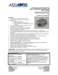
TECHNICAL DATASHEET #TD1102AX<br />
<strong>CONNECTOR</strong> <strong>AMPLIFIER</strong><br />
<strong>FOR</strong> <strong>PROPORTIONAL</strong> <strong>VALVES</strong><br />
(4-<strong>20</strong> mA Input Version)<br />
Part Number: Connector Amplifier<br />
CAPV-H-4-<strong>20</strong>MA-x complete with cable CAPV-4C-yM<br />
Where: x = current output (2A, 1.2A or 600MA)<br />
y = cable length (2 meters is the standard length)<br />
Function: The connector amplifier supplies a solenoid valve with current<br />
proportional to a 4-<strong>20</strong> mA input control signal from a programmable logic<br />
controller (PLC) or other control system.<br />
Features:<br />
• Maximum current adjustment does not affect minimum current setting<br />
• Adjustments accessible with a removable cover<br />
• Broad range of supply voltages (9 to 28 VDC) with no degradation in performance<br />
• Current sensing circuit maintains output regardless of changes in input voltage and coil<br />
resistance<br />
• Modern technology utilizing high frequency switching output (PWM)<br />
• Energy efficient design (no heat sink is required)<br />
• Simple control with a 4-<strong>20</strong> mA signal input<br />
• Options for current output include 2 A, 1.2 A or 600 mA<br />
• Mates to a DIN 43650 plug on a cartridge or block style solenoid valve<br />
• Reverse polarity protection<br />
• Electronic limiting circuit means no internal fuses<br />
• Short circuit proof (in case of solenoid failure or miswiring)<br />
• 2 m cable, unterminated<br />
• Can disconnect load while connector amplifier is powered (“Hot Swap”)<br />
Application: Accurate control of hydraulic and pneumatic proportional solenoid<br />
valves used in mobile construction equipment and industrial processes.<br />
1.0 Introduction:<br />
The User Guide for the connector amplifier describes the installation, set up adjustments<br />
and use of the unit with proportional solenoids.
1.1 Description:<br />
The 4-<strong>20</strong> mA Connector Amplifier simplifies control of proportional solenoids by supplying a<br />
current proportional to an input control (4-<strong>20</strong> mA). It accepts power supply voltages from 9 to 32<br />
VDC. This linear solenoid driver utilizes high frequency switching output (PWM) to provide a DC<br />
current output. The options for maximum current output include 2 A, 1.2 A or 600 mA. A current<br />
sensing circuit maintains output current regardless of changes in input voltage and coil<br />
resistance. The user can adjust maximum and minimum current. Ramp time, dither frequency<br />
and amplitude can also be adjusted to match the application. The unit is available with a DIN<br />
43650 connection to mount directly on the coil. Other versions are available with 0-10 V or 0-5 V<br />
(including 0-<strong>20</strong> mA and 10K potentiometer) inputs. A remote mount version is housed in a rugged<br />
metal box.<br />
TD1102AX 2
1.2 Technical Specifications:<br />
All specifications are typical at nominal input voltage and 25°C unless otherwise specified.<br />
General Specifications<br />
Operating conditions<br />
-40 to +85°C (-40 to 185°F)<br />
Weight<br />
0.40 lbs. (0.18 kg)<br />
Electromagnetic compatibility (EMC) Emission EN 50081-2<br />
Immunity EN 50082-2<br />
Approvals<br />
CE<br />
Packaging, Cable and<br />
Housing:<br />
Electrical connections<br />
Hirschmann GDME <strong>20</strong>11 black housing (PA material, 94 V1),<br />
central screw M3 x 40, transparent cover, washer and o-ring,<br />
nitrile rubber gasket<br />
DIN 43650-A contact arrangement with 18 mm spacing<br />
(plug-style to mount on valve)<br />
Contacts: Sn, PA, 94V1<br />
Approvals: VDE, SEV, GL<br />
(A version for remote mounting is also available.)<br />
Cable:<br />
2 metre cable, 4 conductor, unterminated, 18 AWG<br />
For pin out, refer to Section 2.3.<br />
Manufacturer: Phoenix EDT Inc. P/N: D0518004-8<br />
Conductors: Stranded, tin-plated copper<br />
Jacket: PVC<br />
Insulation: SR-PVC<br />
Cable Markings: UL AWM, CM, CSA AWM II A/B, CMG FT4<br />
Protection class<br />
IP65 when correctly installed with lid, o-ring/washer<br />
and base gasket<br />
Dimensions in mm/inches<br />
(excluding cable)<br />
Length L1 85.35mm 3.36”<br />
L2 61.75mm 2.43”<br />
L3 34.00mm 1.34”<br />
Width = L3 34.00mm 1.34”<br />
Height H1 38.00mm 1.49”<br />
Electrical Specifications<br />
Operating voltage (power supply requirement)<br />
Control input signal options<br />
Input resistance<br />
Range of maximum output current<br />
9 to 28 VDC power supply range<br />
Accepts up to a maximum of 32 VDC<br />
4-<strong>20</strong> mA current signal<br />
(0-10 V and 0-5 VDC/0-<strong>20</strong> mA/10K potentiometer control input<br />
versions are also available.)<br />
50 Ohms<br />
2 A (1.2 A and 600 mA versions available)<br />
Solenoid resistance selection (nominal)<br />
Nominal resistance of solenoid coil should comply with:<br />
Rcoil < (Vpower supply - 1.5 V)/I-max.<br />
Note 1: For proper operation of the amplifier, match power supply voltage with rating of solenoid coil. Operating the<br />
amplifier with a supply voltage lower than the solenoid rated voltage may result in reduced maximum current output.<br />
Note 2: The coil should have no polarity or protection diodes for proper operation of the device.<br />
Note 3: The maximum current output of the amplifier should not exceed the current rating of the solenoid coil.<br />
TD1102AX 3
Adjustments<br />
Minimum current setting<br />
Maximum current setting<br />
Current ramp time<br />
Dither amplitude<br />
Current dither frequency<br />
0 to 0.5 A (for 2 A output model)<br />
0 to 0.3 A (for 1.2 A output model)<br />
0 to 150 mA (for 600 mA output model)<br />
0.6 to 2.0 A (for 2 A output model)<br />
0.36 to 1.2 A (for 1.2 A output model)<br />
180 to 600 mA (for 600 mA output model)<br />
0.01 - 5 sec. independent<br />
0 to 10% of rated maximum current<br />
70 to 350 Hz (±10% of full scale)<br />
2.0 Installation Procedures:<br />
2.1 Precautions Against Leaks From The Environment<br />
Ensure the transparent lid is firmly in place.<br />
Ensure the brown rubber base gasket is in place, providing a seal between the proportional valve<br />
controller/amplifier and the plug on the valve.<br />
The mounting screw, compression washer and o-ring assembly should be flush with the top of the<br />
lid and fastened in place. Tighten the screw to make a firm connection to the valve with a Phillips<br />
#2 screwdriver.<br />
TD1102AX 4
2.2 Necessary Equipment<br />
• Connector amplifier<br />
• Cartridge or Block Proportional Solenoid Valve ready to accept a DIN 43650 plug<br />
• Hydraulic power source and load circuit<br />
• Power Supply (9 to 32 VDC)<br />
• DC voltmeter (optional)<br />
• Input: 4-<strong>20</strong>mA current signal<br />
• External fusing recommended (3A)<br />
2.3 Connection<br />
• Supply voltage should be between 9 and 32 VDC. Excess voltage will damage the unit.<br />
Match the power supply voltage with the voltage rating of the solenoid coil. Operating the<br />
amplifier with a supply voltage lower than the solenoid rated voltage may result in reduced<br />
maximum current output.<br />
• The maximum current output of the amplifier should not exceed the current rating of the<br />
solenoid coil.<br />
• The coil should have no polarity or protection diodes for proper operation of the device.<br />
• Do not install the amplifier near high voltage relays or other sources of electrical interference.<br />
• Connect the power supply, input signal and valve solenoid as shown below.<br />
• Set the input signal to the maximum level and confirm it is operating properly.<br />
TD1102AX 5
2.4 Wiring Connections<br />
Connect the cable conductors to the power supply and input signal as follows.<br />
For 4-<strong>20</strong> mA Control:<br />
Turn ramp screws fully counterclockwise to eliminate ramping.<br />
Use I-Min. screw to set up minimum speed with minimum control input.<br />
Use I-Max. screw to set maximum speed with 100% of control input.<br />
Refer to page 2 (block diagram) for an<br />
alternative method of connecting a current<br />
loop transmitter to provide a current control<br />
signal input. In this method, the current loop<br />
transmitter receives power from the power<br />
supply powering the amplifier. The transmitter<br />
is connected to the amplifier’s +power supply<br />
input wire and the +4 to <strong>20</strong>mA input wire. This<br />
method does not use the – 4 to <strong>20</strong>mA input<br />
signal wire connection.<br />
3.0 Set Up Adjustment Procedures:<br />
The location of the trim pots for the set up adjustments is shown in section 2.3.<br />
3.1 Preparation<br />
Ensure that the connector amplifier is connected to an operating proportional valve.<br />
Use a small screwdriver to loosen the mounting screw and remove the transparent lid.<br />
The trim pots are adjusted with a slotted 1.5 screwdriver.<br />
3.2 Interaction Between Maximum and Minimum Current Adjustments<br />
Adjusting the maximum current (I-max.) does not affect the minimum current (I-min.) setting.<br />
Adjusting the minimum current will shift<br />
the maximum current setting, as<br />
shown.<br />
TD1102AX 6
3.3 Connector Amplifier Settings<br />
The following settings represent a typical set up. I-min and I-max are multi-turn trim pots with a<br />
range of 10 turns. Ramp time, dither amplitude and frequency trim pots are single turn. Use a<br />
slotted 1.5 screwdriver.<br />
Trim Pot Adjustments Range of Adjustment Factory Setting<br />
Zero - Minimum Current Setting 0 to 0.5 A (for 2 A output model)<br />
0% (CCW)<br />
(I-min.)<br />
0 to 0.3 A (for 1.2 A output model)<br />
Span - Maximum Current Setting<br />
(I-max.)<br />
0 to 150 mA (for 600 mA output model)<br />
0.6 to 2.0 A* (for 2 A output model) 100% (CW)<br />
0.36 to 1.2 A (for 1.2 A output model)<br />
180 to 600 mA (for 600 mA output model)<br />
0.01 to 5 seconds independent minimum (0.01<br />
seconds) (CCW)**<br />
Ramp Time (Rising and Falling<br />
Edge)<br />
Dither Level (Amplitude) 0 to 10% of rated maximum current 0% (CCW)<br />
Dither Frequency 70 to 350 Hz (±10%) minimum (CCW)<br />
CW = clockwise, CCW = Counter clockwise<br />
∗NOTE 1: Range of maximum output current is 2A (maximum output current = min. current setting + max. current<br />
setting).<br />
**NOTE 2: To eliminate ramping, turn the trim pots fully counter clockwise.<br />
Setting the Minimum Current (I-min.)<br />
• Set the minimum current before setting the maximum current.<br />
• Apply minimum input (4 mA).<br />
• The factory setting for the I-min. trim pot is 0 or fully counter clockwise (CCW).<br />
• If the desired minimum current is greater than 0, adjust the trim pot clockwise (CW) until the<br />
desired current is achieved.<br />
The minimum current setting can be used to take into account the mechanical valve deadband<br />
and provide desired offsets from zero to allow full control within the functional range of the<br />
specific valve.<br />
Setting the Maximum Current (I-max.)<br />
• Apply maximum control (<strong>20</strong> mA).<br />
• The factory setting for the I-max. trim pot is 100% or fully CW.<br />
• Turn the trim pot CCW to adjust the current setting downwards to the desired maximum.<br />
The maximum current setting is adjusted to meet the customer’s working pressure or flow range<br />
to the full scale signal input range. This provides maximum control for a specific application.<br />
Setting the Ramp Times<br />
• The factory setting for ramp times is the minimum (0.01 seconds) or fully CCW.<br />
• If the ramp time settings are not needed, leave the setting at the minimum value.<br />
• To change the ramp times, adjust the trim pot CW to increase the time.<br />
• Note that rising and falling ramp times are independent.<br />
TD1102AX 7
Ramp times are application dependent. They limit the rate of change or how fast the operation<br />
happens. Note that if the input signal is not applied long enough for the ramp time set, the<br />
desired solenoid current will not be reached.<br />
Setting the Dither Amplitude<br />
• The factory setting for dither amplitude is 0% (CCW).<br />
• To adjust dither amplitude, turn the trim pot CW until small changes in the input signal<br />
register similar changes in current output.<br />
• Choose the smallest effective dither amplitude.<br />
Dither amplitude is adjustable from 0 to 10% of the rated maximum current. Dither amplitude and<br />
frequency are dependent on the specific valve. The effects of static friction on the operation of<br />
the solenoid are reduced by the application of a small AC current. The hysteresis and<br />
repeatability of the valve are improved by this practice. The optimum dither amplitude is attained<br />
when small input signal changes register similar changes in current output (pressure or flow<br />
through the valve).<br />
Setting the Dither Frequency<br />
• The factory setting for dither frequency is the minimum or 0% (CCW).<br />
• To adjust dither frequency, turn the trim pot CW until the desired frequency is set.<br />
• Refer to the proportional valve manufacturer’s catalogue for the dither frequency rating of a<br />
particular valve.<br />
4.0 Start Up Procedures:<br />
A typical start up procedure is as follows:<br />
1. Ensure the lid with o-ring, compression washer (next to the screw) and base gasket are<br />
correctly in place (necessary for IP65 protection).<br />
2. Ensure that no damage or injury can occur on the machine when the valve is operated.<br />
3. Attach the connector amplifier to the load.<br />
4. Connect the power supply to the proportional valve controller/amplifier and apply a control<br />
signal.<br />
5. Set I-min., I-max., ramps and dither to suit the application.<br />
Successful completion of these five steps means the connector amplifier and load are ready for<br />
normal use.<br />
TD1102AX 8
5.0 Operation:<br />
The connector amplifier ensures a hydraulic proportional valve will function in a manner directly<br />
proportional to the control input. Accurate and repeatable operation is attained. The unit<br />
performs within the mechanical limits of the proportional valve. No maintenance of the unit is<br />
required.<br />
6.0 Ordering Part Number:<br />
Connector Amplifier<br />
CAPV-H-4-<strong>20</strong>MA-x complete with cable CAPV-4C-yM<br />
Where: x = current output (2A, 1.2A or 600MA)<br />
y = cable length (2 meters is the standard length)<br />
Specifications are indicative and subject to change. Actual performance will vary depending on the application and<br />
operating conditions. Users should satisfy themselves that the product is suitable for use in the intended application. All<br />
our products carry a limited warranty against defects in material and workmanship. Please refer to our Warranty,<br />
Application Approvals/Limitations and Return Materials Process as described on www.axiomatic.com/service.html.<br />
Form: TD1102AX-06/17/11<br />
TD1102AX 9