OPERATOR'S AND PARTS MANUAL - Walker Mowers
OPERATOR'S AND PARTS MANUAL - Walker Mowers
OPERATOR'S AND PARTS MANUAL - Walker Mowers

Create successful ePaper yourself
Turn your PDF publications into a flip-book with our unique Google optimized e-Paper software.
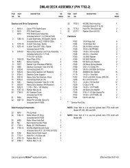
ROTARY BROOM ASSEMBLY<br />
ASSEMBLY<br />
The rotary broom is assembled at the factory, however, parts contained in the bag must be installed.<br />
Use the present manual and lay out all parts for assembly. Separate bolts and nuts into various sizes.<br />
After assembly, torque all the bolts according to the Torque Specification Table enclosed at the end of<br />
the manual.<br />
Parking Stand<br />
(Figure 8)<br />
1. Lift the broom until you can insert a parking<br />
stand (item 1) into each holder from the<br />
underside.<br />
2. Install a 5/32" x 1 1/4" cotter pin (item 2) in<br />
the upper hole of each parking stand.<br />
3. Set the parking stands in the position<br />
where they touch the ground and secure<br />
with 1/4" x 2" round wire lock pins (item 3).<br />
Figure 8<br />
Attaching Rotary Broom to Tractor<br />
(Figures 9-10)<br />
IMPORTANT: Make sure the pivot lock pin<br />
(fig 10, item A) is in the innermost position<br />
to prevent female hitch from bouncing and<br />
to facilitate hitching<br />
1. Support the broom female hitch (item 1) on<br />
a 2 1/2" (60 mm) thick piece of wood.<br />
2. Move quick hitch lever (item 8) rearward to<br />
unlock position.<br />
3. Connect the male driveline (item 2)<br />
supplied with the drive kit to broom female<br />
driveline (item 3) and support with the<br />
driveline support (item 5).<br />
4. Lower the nose of the male quick hitch as<br />
much as possible.<br />
5. Introduce the male quick hitch (item 4) in<br />
the broom female hitch (item 1) and move<br />
the engagement lever (item 8) forward to<br />
locked position. Secure latch (item 7) with<br />
linch pin (item 6).<br />
6. Connect male driveline (item 2) to subframe<br />
drive shaft by sliding back locking collar on<br />
driveline yoke and pushing yoke over shaft<br />
until locking collar snaps back and push<br />
driveline support down (item 5).<br />
WARNING:<br />
To avoid serious personal injuries:<br />
Before getting off the tractor: Park the<br />
tractor on level ground, place the<br />
transmission in neutral, set the<br />
parking brake, disengage the driving<br />
system, lower the nose of the male<br />
quick hitch as much as possible, place<br />
all levers including auxiliary control<br />
levers in neutral, shut off the engine<br />
and remove the ignition key.<br />
Figure 9<br />
OM 0182BR47-A 12