Instruction Manual - Farmi Forest
Instruction Manual - Farmi Forest
Instruction Manual - Farmi Forest

Create successful ePaper yourself
Turn your PDF publications into a flip-book with our unique Google optimized e-Paper software.
<strong>Instruction</strong> <strong>Manual</strong><br />
Remote Control system RC400<br />
Document Revision Language<br />
66024 C English
Document type Document number Rev Page<br />
<strong>Manual</strong> 66024 C 2 of 37<br />
Contents<br />
1 General ................................................................................. 3<br />
1.1 Terminology 3<br />
2 Preface ................................................................................. 4<br />
2.1 General information 4<br />
3 General system description.................................................... 5<br />
3.1 Schematic overview of Scanreco RC-400 5<br />
3.2 General description of Scanreco RC-400 6<br />
3.3 The Portable Control Unit (PCU) 7<br />
3.4 Central unit (CU) 13<br />
3.5 Valve and connection-cables 15<br />
3.6 Crane stop function box (optional) 19<br />
3.7 Battery pack 20<br />
3.8 Battery charger and battery charging 22<br />
4 Safety regulations and operating instructions .......................25<br />
4.1 Safety regulations 25<br />
4.2 Operating instructions 26<br />
5 Installation <strong>Instruction</strong>s.......................................................27<br />
5.1 General schematic of the RC 400 27<br />
5.2 Important notice during welding 27<br />
5.3 Locating the central unit 27<br />
5.4 Mounting recommendations 28<br />
5.5 Cable kit assembly instruction 29<br />
6 Troubleshooting ...................................................................31<br />
6.1 General information 31<br />
6.2 Indications from the Portable Control Unit 31<br />
6.3 Indications on the Central Unit 33<br />
6.4 Non-functional system 35<br />
7 Programming parameters and settings..................................36<br />
7.1 General description 36<br />
7.2 Authorisation level 1 37<br />
All rights reserved.<br />
Design, equipment, technical data and specification are subject to change or improvement<br />
without prior notice. The text of this manual, or any part thereof, may not be reproduced or<br />
transmitted in any form or by any means, electronic or mechanical including photocopying,<br />
recording, storage in an information retrieval system, or otherwise, without the prior written<br />
permission of Scanreco AB, Sweden.
Document type Document number Rev Page<br />
<strong>Manual</strong> 66024 C 3 of 37<br />
Document information<br />
Attribute<br />
Document type<br />
Title<br />
Subtitle<br />
Information<br />
<strong>Manual</strong><br />
<strong>Instruction</strong> manual<br />
Remote Control System Scanreco RC-400<br />
Document number 66024<br />
Revision<br />
C<br />
Revision date 2009-09-25<br />
Revision history<br />
Revision Date Name Note<br />
A 2008-12-09 SCANRECO AB First creation of document<br />
B 2009-06-15 SCANRECO AB<br />
C 2009-09-25 SCANRECO AB<br />
1 General<br />
1.1 Terminology<br />
Abbreviation<br />
PCU<br />
CU<br />
LED<br />
DV<br />
Description<br />
Portable Control Unit<br />
Central Unit<br />
Light Emitting Diode<br />
Dump Valve
Document type Document number Rev Page<br />
<strong>Manual</strong> 66024 C 4 of 37<br />
2 Preface<br />
2.1 General information<br />
This manual is intended as a complement to the crane / machine instruction book<br />
and covers the Scanreco RC 400 Remote Control System.<br />
The Scanreco RC 400 offers the driver an extremely advanced remote control system<br />
with speed, precision, control and maximum safety.<br />
In order to ensure your safety and the safety of your crane / machine you should<br />
study and learn these instructions. This will enable you to quickly familiarise yourself<br />
with your new remote control system and how to utilise it.<br />
• Remotely controlled cranes may only be operated by qualified personnel. The<br />
driver must be aware of the contents of chapter 4 "Safety regulations and<br />
Operating instructions" before operation is started. Serious accidents may<br />
occur if these instructions are not followed.<br />
• To protect the portable control unit from damage and for safety reasons, the<br />
control unit must be kept in a locked cab.<br />
• Follow the instructions given in the crane handbook regarding moving the<br />
crane from its parking position, the best arm positioning while loads are being<br />
handled and parking of the crane.<br />
• Due to the unlimited variety of cranes, machines, objects, vehicles and<br />
equipment on which the remote control system are used, and the numerous<br />
standards which are frequently the subject of varying interpretation, it is<br />
impossible for the personnel at Scanreco to provide expert advice regarding<br />
the suitability of a given remote control for a specific application. It is the<br />
responsibility of the purchaser to determine the suitability of any Scanreco<br />
remote control product for an intended application and to insure that it is<br />
installed and guarded in accordance with all country, federal, state, local, and<br />
private safety and health regulation, codes, standards and Scanreco<br />
recommendation (this manual). If the Scanreco RC 400 will be used in a<br />
safety critical application, the customer / driver must undertake appropriate<br />
testing and evaluation to prevent injury to the ultimate user. Scanreco does<br />
not take responsibility for any damage or injure<br />
• Unauthorized tampering with Scanreco automatically invalidates guarantee.<br />
To the operator:<br />
Pause for a while and give yourself extra time to read chapters 3 (General system<br />
description) and 4 (Safety regulations and Operating instructions).<br />
To the installer:<br />
Pause for a while and give yourself extra time to read chapters 5 (Installation<br />
instructions) and "Inspection / Installation documents”.
Document type Document number Rev Page<br />
<strong>Manual</strong> 66024 C 5 of 37<br />
3 General system description<br />
3.1 Schematic overview of Scanreco RC-400<br />
The Remote Control System is comprised of the following components (see figure<br />
3.1):<br />
1<br />
5<br />
2<br />
4<br />
3<br />
6<br />
7 8<br />
Figure 3.1 Schematic overview of the Scanreco RC-400.<br />
General scope of delivery (see your specification and Figure 3.1).<br />
No Description Qty<br />
1 Portable Control unit (PCU) 1<br />
2 Central unit (CU) 1<br />
3 Battery charger 1<br />
4 Battery cassette (NiMH 7.2 VDC) 2<br />
5 Manoeuvre cable (10 meters) 1<br />
6 Emergency stop box (Optional) 1<br />
7 Cable kit supply cables + digital outputs 1<br />
8 Cable kit valves cables (analogue outputs) 1
Document type Document number Rev Page<br />
<strong>Manual</strong> 66024 C 6 of 37<br />
3.2 General description of Scanreco RC-400<br />
The Scanreco RC 400 remote control system has been especially developed for<br />
hydraulically driven mobile cranes and machinery. The system is a digital remote<br />
control system based on an extremely advanced microprocessor technology. Years of<br />
exhaustive and demanding testing have shown that the remote control system can<br />
cope with the roughest of environments.<br />
The system is protected against electromagnetic and radio frequency radiation and<br />
can be installed onto all hydraulic valve types (voltage, current pulse width, or<br />
protocol steered) found on the market.<br />
In its basic form the remote control system is comprised of a portable control unit<br />
with manoeuvre levers for proportional control and switches for ON/OFF functions, a<br />
central unit with connection cable for driving proportional electro-hydraulic slide<br />
controllers.<br />
Digitally coded control information (lever deflection and switch position) is sent from<br />
the control unit via electric cable or via radio to the central unit. The control unit and<br />
central unit translate the magnitude and direction of the manoeuvre lever deflections<br />
and switch positions to corresponding valve function, speed and direction and thus<br />
crane movement.<br />
Important notice:<br />
The Scanreco Remote control system RC-400 described in this instruction manual<br />
should be distinguished from the similar Scanreco remote control systems RC-400 G4<br />
as the main components in these two system types product family (Portable control<br />
units and central units) are not compatible with each other and varies in appearance<br />
and functionality.
Document type Document number Rev Page<br />
<strong>Manual</strong> 66024 C 7 of 37<br />
3.3 The Portable Control Unit (PCU)<br />
The Portable Control Unit is impact, weather resistant, light weight and compact. The<br />
portable control units can be with linear levers or with joysticks (see figure 3.2<br />
below).<br />
Figure 3.2 The available range of portable control units.<br />
No Description<br />
1 MAXI-Joystick is available for 1-8 (Setup: 2-0-2 / 2-2-2 / 2-3-2 / 3-2-3 / 3-0-3).<br />
2 MAXI-Linear is available for 1-8 linear levers<br />
3 MINI-Joystick is available for 1-6 (Setup: 2-0-2 / 2-2-2).<br />
4 MINI-Linear is available for 1-6 linear levers<br />
The manoeuvre levers and joysticks are fully proportional and have spring return to<br />
the zero position, i.e. a "dead-man's-handle". The control units have a stop function<br />
which will immediately stop all movement.<br />
All manoeuvre levers/joysticks are protected with a protective frame against<br />
unintentional activation and against mechanical damage. The control unit has multistep<br />
micro-speed operation as standard enabling instantaneous temporary reduction<br />
of speed. It can also be equipped with a large number of switches for ON/OFF<br />
functions. A LED and sound signal are used to indicate such things as operating and<br />
battery status and for a simple and diagnostic fault finding (see Figure 3.4).
Document type Document number Rev Page<br />
<strong>Manual</strong> 66024 C 8 of 37<br />
3.3.1 Battery operation<br />
A battery is located in the lower part of the control unit for radio control operation<br />
and is very simple to change.<br />
• The effective operation time of the battery is about 8 hours on one charge.<br />
• When the battery is approaching time for charging, the control unit beeps three<br />
(3) times as a warning and at the same time the LED starts to blink on the<br />
control unit.<br />
• The battery must be used until the LED goes out, after which it can be changed.<br />
If the battery capacity is too low the control unit cannot be activated.<br />
• The battery capacity and operational performance is reduced in extremely cold<br />
conditions. The battery is automatically charged during operation by cable<br />
control.<br />
• In order to reduce battery loading and for safety reasons, the control unit is<br />
turned off automatically, after the unit has been idle for more than approximately<br />
five (5) minutes.<br />
3.3.2 Manoeuvre levers / joystick<br />
The control unit is comprised of manoeuvre levers for proportional control, switches<br />
for ON/OFF, micro-operation and stop function (see separate headings below).<br />
Figure 3.3 Overview of panel of PCU.
Document type Document number Rev Page<br />
<strong>Manual</strong> 66024 C 9 of 37<br />
3.3.3 Stop function panel<br />
There is a red stop function switch (STOP) with a manual twist reset, a push button<br />
and a red LED on the control unit's stop function panel, see figure 3.4.<br />
The control unit is started with the spring reset push button ( )<br />
All movement of the crane is stopped if the stop function is activated on the control<br />
unit. The red LED indicates operating and battery status.<br />
Figure 3.4 View of a stop function panel.<br />
3.3.4 Changing radio channels<br />
It is possible to change the radio channel by quickly pressing the button marked<br />
twice. There are 10 different radio channels to switch between by pressing this<br />
button in sequence.<br />
Important notice:<br />
Scanreco will introduce an automatic frequency management to the RC400 systems<br />
in end of 2009 making the above described function; chapter 3.3.4 changing radio<br />
channels, obsolete.<br />
The automatic frequency management ensures a more reliable radio transmission<br />
highly resistant to radio interference thanks to intelligent frequency hopping<br />
technology automatically handling frequency changes.<br />
The operator then no longer needs to manage radio frequency and the risk of<br />
interference is minimized.<br />
This user manual is printed prior to the introduction of the automatic frequency<br />
management, for further information; please consult your distributor.
Document type Document number Rev Page<br />
<strong>Manual</strong> 66024 C 10 of 37<br />
3.3.5 Switch Panels<br />
The switches on the switch panel allow actuation of digital functions via toggle<br />
switches and push buttons, see figure 3.5 and 3.6. digital functions can be used to<br />
manoeuvre electrical, hydraulic or pneumatic ON/OFF functions. Examples of<br />
functions:<br />
• Stopping and starting of the vehicle's motor, throttle lever, beep / signal,<br />
change-over valves, function changing for ex. 7:th and 8:th function, etc.<br />
Make sure that you always know which digital functions that are connected for<br />
ON/OFF manoeuvring.<br />
Figure 3.5 Left switch panel on MAXI PCU.<br />
Figure 3.6 Left switch panel on MINI PCU.
Document type Document number Rev Page<br />
<strong>Manual</strong> 66024 C 11 of 37<br />
3.3.6 Micro-speed control<br />
This return spring switch can be used to reduce the operating speed in five (5) steps<br />
from 100% to 60%, 50%, 40%, 30% and 20% speed by limiting the hydraulic<br />
steering. The regulation of the function's speed is still made over the entire lever<br />
stroke and with retained resolution.<br />
• With impulses from the spring loaded toggle switch to the left, towards the turtle<br />
, speed reduction can be produced from 100% to 60%, 50%, 40%, 30%<br />
and 20% steering.<br />
• Movement of the switch to the right, towards the rabbit , will produce 100%<br />
steering once again.<br />
• For safety reasons, a return to 100% steering can only be made if all manoeuvre<br />
levers are in their zero positions.<br />
• When the green LED is blinking, the Micro-speed function is activated. The<br />
number of blinks indicates the operating speed as defined in the table below. If<br />
the stop function is pressed on the controller unit, the controller unit will start<br />
from the last chosen speed.<br />
Green LED<br />
not lit<br />
Indication<br />
0 to 100 % speed (normal speed)<br />
1 blink every third second 0 to 60 % speed<br />
2 blink every third second 0 to 50 % speed<br />
3 blink every third second 0 to 40 % speed<br />
4 blink every third second 0 to 30 % speed<br />
5 blink every third second 0 to 20 % speed
Document type Document number Rev Page<br />
<strong>Manual</strong> 66024 C 12 of 37<br />
3.3.7 Cable for cable control<br />
The control unit can be connected to the central unit via a thin and flexible 5-core<br />
cable. The cable has round contacts (M12) at each end.<br />
The cable feeds the digital coded control information from the Portable Control Unit to<br />
the Central Unit. The cable is available in standard lengths of 10 meters.<br />
Pin no<br />
1 Data<br />
2 GND<br />
Function<br />
3 RS232 TX<br />
4 RS232 RX<br />
5 +24 VDC<br />
3.3.8 Technical data (PCU)<br />
Item<br />
Battery pack<br />
Portable Control Unit effective<br />
operating time<br />
Weight / MAXI/Linear<br />
Weight / MAXI/Joystick<br />
Weight / MINI/Linear<br />
Weight / MINI/Joystick<br />
Dimensions MAXI (WxHxD)<br />
Dimensions MINI (WxHxD)<br />
IP class<br />
Ambient temperature (Celsius /<br />
Farenheit)<br />
Technical data<br />
7.2 VDC<br />
Approximately 8 hours per charge<br />
1,95/2,20 kg (without/with battery pack)*<br />
1,75/2,00 kg (without/with battery pack)*<br />
1,45/1,70 kg (without/with battery pack)*<br />
1,30/1,55 kg (without/with battery pack)*<br />
350x160x190 mm*<br />
290x160x190 mm*<br />
IP65<br />
-25°C to +70°C /approx. -15°F to to +160°F<br />
*Weights and dimensions are approximate and depending on configuration.
Document type Document number Rev Page<br />
<strong>Manual</strong> 66024 C 13 of 37<br />
3.4 Central unit (CU)<br />
The central unit is manufactured in plastic and is provided with contacts for<br />
connection to the portable control unit (for cable remote operation), for supply<br />
voltage, the electro-hydraulic converter valves, dump valve and ON/OFF functions.<br />
Since the central unit can be exposed to very tough environments, the box is<br />
encapsulated to give protection from damp, heat, cold, dust, vibration and corrosive<br />
environments.<br />
The central unit has short circuit proof inputs and outputs and has protection against<br />
polarity reversal, over-voltage, large incoming voltage transients and EMC / RF.<br />
Connection of the central unit can therefore be made without risk of damage. The<br />
central unit is delivered for supply voltages of +12 / +24 VDC (+/- 20 %) with<br />
negative ground. There is one standard car type fuse located inside the central unit.<br />
Plus fuse: + 10 Amp.<br />
A transformer for standard mains voltages can also be used to provide the central<br />
unit with supply voltage. Primary voltage: 110, 115, 220-240, 380, 440 VAC and<br />
secondary voltage + 12 / +24 VDC (+/- 10%).<br />
The central unit is equipped with:<br />
1. Standard antenna<br />
2. Operational mode switch (Remote/<strong>Manual</strong>: See Chapter 4.2 Operational<br />
instructions)<br />
3. Cable connector for cable control / Programming port<br />
4. Status LED´s<br />
5. 7-segment LED Display<br />
1<br />
1<br />
2<br />
3<br />
2<br />
3<br />
5<br />
4<br />
Figure 3.7 The central unit.
Document type Document number Rev Page<br />
<strong>Manual</strong> 66024 C 14 of 37<br />
3.4.1 Technical data (CU)<br />
Item<br />
Supply voltage<br />
Internal fuse<br />
Max. over-voltage<br />
Proportional functions<br />
Dump valve drive<br />
ON/OFF drive<br />
Regulation signals<br />
Current consumption at idle<br />
Weight<br />
Dimensions (WxHxD)<br />
IP Class<br />
Ambient temperature (Celsius /<br />
Farenheit)<br />
Technical data<br />
12 VDC / 24 VDC (+/- 20% / max. 5% V peak to<br />
peak)<br />
Plus: + 10 Amp. (Standard car fuse / Red)<br />
Approximately 33 VDC (Fuse blows)<br />
1 - 8 double operating proportional functions<br />
Max. 2,0 Ampere (short circuit proof)<br />
Max. 1,8 Ampere (short circuit proof)<br />
Voltage or PWM (Other upon request)<br />
40 mA<br />
1,20 Kg (Valve and connection cables not<br />
included)<br />
227x205x78 mm<br />
IP65<br />
-25°C to +70°C /approx. -15°F to to +160°F
Document type Document number Rev Page<br />
<strong>Manual</strong> 66024 C 15 of 37<br />
3.5 Valve and connection-cables<br />
There are several connection cables depending on the valves and the extra functions<br />
used. In Figure 3.8 an example of a cable kit to Danfoss valves is shown.<br />
Figure 3.8 An example of a cable kit to Danfoss valves.
Document type Document number Rev Page<br />
<strong>Manual</strong> 66024 C 16 of 37<br />
3.5.1 Terminal connections<br />
K7 ( + / -, DV)<br />
K1 (Analog outputs 1-4)<br />
K4 (EX1)<br />
K3 (Analog outputs 5-8)<br />
K6 (EX2)<br />
Figure 3.9 The figure illustrates inside terminal connectors for the standard Central<br />
Units type 2000 (Danfoss) and type 3000 (PWM).<br />
Important notice:<br />
If a central unit is delivered without pre-mounted cables; the installer is strongly<br />
advised to follow the instructions given in chapter 5.5 in this manual, pages 27 and<br />
28; Installation instructions - Cable kit assembly instruction.
Document type Document number Rev Page<br />
<strong>Manual</strong> 66024 C 17 of 37<br />
3.5.2 Terminal schematics for Danfoss type Central Unit<br />
K7 Main<br />
Pin no. Description<br />
K7.1 Supply (+12/24 VDC)<br />
K7.2 GND<br />
K7.3 DV +<br />
K7.4 DV GND<br />
K1 Analog outputs K3 Analog outputs<br />
Pin no. No. Description Pin no. No. Description<br />
K1.1 Danfoss module supply K3.1 Danfoss module supply<br />
K1.2 Danfoss regulated supply K3.2 Danfoss regulated supply<br />
1<br />
5<br />
K1.3 GND K3.3 GND<br />
K1.4<br />
Fault monitor K3.4<br />
Fault monitor<br />
K1.5 Danfoss module supply K3.5 Danfoss module supply<br />
K1.6 Danfoss regulated supply K3.6 Danfoss regulated supply<br />
2<br />
6<br />
K1.7 GND K3.7 GND<br />
K1.8<br />
Fault monitor K3.8<br />
Fault monitor<br />
K1.9 Danfoss module supply K3.9 Danfoss module supply<br />
K1.10 Danfoss regulated supply K3.10 Danfoss regulated supply<br />
3<br />
7<br />
K1.11 GND K3.11 GND<br />
K1.12<br />
Fault monitor K3.12<br />
Fault monitor<br />
K1.13 Danfoss module supply K3.13 Danfoss module supply<br />
K1.14 Danfoss regulated supply K3.14 Danfoss regulated supply<br />
4<br />
8<br />
K1.15 GND K3.15 GND<br />
K1.16<br />
Fault monitor K3.16<br />
Fault monitor<br />
K4 EX1 - Digital outputs / inputs K6 EX2 - Digital outputs / inputs<br />
Pin no. Description Pin no. Description<br />
K4.1 Digital output 1 K6.1 On / Signal<br />
K4.2 Digital output 2 K6.2 Digital output 7<br />
K4.3 Digital output 3 K6.3 Digital output 8<br />
K4.4 Digital output 4 K6.4 Digital output 9<br />
K4.5 Digital output 5 K6.5 GND<br />
K4.6 Digital output 6 K6.6 Digital output 10<br />
K4.7 GND K6.7 Digital output 11<br />
K4.8 Digital input 1 K6.8 Digital output 12 / Digital input 4<br />
K4.9 Digital input 2 K6.9 Digital output 13<br />
K4.10 Digital input 3 K6.10 GND<br />
K4.11 Input supply (+VDC)<br />
K8 EX3 - Optional features<br />
Pin no. Description<br />
K8.1 Customer specific<br />
K8.2 Customer specific<br />
K8.3 Customer specific<br />
K8.4 Customer specific<br />
K8.5 Customer specific
Document type Document number Rev Page<br />
<strong>Manual</strong> 66024 C 18 of 37<br />
3.5.3 Terminal schematics for PWM type Central Unit<br />
K7 Main<br />
Pin no. Description<br />
K7.1 Supply (+12/24 VDC)<br />
K7.2 GND<br />
K7.3 DV +<br />
K7.4 DV GND<br />
K1 Analog outputs K3 Analog outputs<br />
Pin no. No. Description Pin no. No. Description<br />
K1.1 PWM + K3.1 PWM +<br />
1A 5A<br />
K1.2<br />
GND K3.2 GND<br />
K1.3 PWM + K3.3 PWM +<br />
1B 5B<br />
K1.4<br />
GND K3.4 GND<br />
K1.5 PWM + K3.5 PWM +<br />
2A 6A<br />
K1.6<br />
GND K3.6 GND<br />
K1.7 PWM + K3.7 PWM +<br />
2B 6B<br />
K1.8<br />
GND K3.8 GND<br />
K1.9 PWM + K3.9 PWM +<br />
3A 7A<br />
K1.10<br />
GND K3.10 GND<br />
K1.11 PWM + K3.11 PWM +<br />
3B 7B<br />
K1.12<br />
GND K3.12 GND<br />
K1.13 PWM + K3.13 PWM +<br />
4A 8A<br />
K1.14<br />
GND K3.14 GND<br />
K1.15 PWM + K3.15 PWM +<br />
4B 8B<br />
K1.16<br />
GND K3.16 GND<br />
K4 EX1 - Digital outputs / inputs K6 EX2 - Digital outputs / inputs<br />
Pin no. Description Pin no. Description<br />
K4.1 Digital output 1 K6.1 On / Signal<br />
K4.2 Digital output 2 K6.2 Digital output 7<br />
K4.3 Digital output 3 K6.3 Digital output 8<br />
K4.4 Digital output 4 K6.4 Digital output 9<br />
K4.5 Digital output 5 K6.5 GND<br />
K4.6 Digital output 6 K6.6 Digital output 10<br />
K4.7 GND K6.7 Digital output 11<br />
K4.8 Digital input 1 K6.8 Digital output 12 / Digital input 4<br />
K4.9 Digital input 2 K6.9 Digital output 13<br />
K4.10 Digital input 3 K6.10 GND<br />
K4.11 Input supply (+VDC)<br />
K8 EX3 - Optional features<br />
Pin no. Description<br />
K8.1 Customer specific<br />
K8.2 Customer specific<br />
K8.3 Customer specific<br />
K8.4 Customer specific<br />
K8.5 Customer specific
Document type Document number Rev Page<br />
<strong>Manual</strong> 66024 C 19 of 37<br />
3.6 Crane stop function box (optional)<br />
The crane stop function box is a separate unit for fixed mounting on the vehicle (see<br />
figure 3.10). The crane stop function box must be connected between the vehicle<br />
battery and the central unit.<br />
• When the stop function is activated the main power supply to the entire remote<br />
control system is disconnected.<br />
• The crane stop function must be suitably located and easily accessible.<br />
• Before operation is started, the driver must inform all fellow-workers about the<br />
stop function and its location.<br />
• Crane stop function box is not a scope of delivery from Scanreco – it is the<br />
installers responsibility.<br />
With the central unit switch in MANUAL position and an electric dump valve, the stop<br />
function is also available during manual hand lever operation. (See also chapter 4<br />
"Safety regulations and Operating instructions").<br />
Figure 3.10 Stop function box.
Document type Document number Rev Page<br />
<strong>Manual</strong> 66024 C 20 of 37<br />
3.7 Battery pack<br />
The battery pack is impact and weather resistant and is located in the battery holder<br />
in the Portable Control Unit. The battery pack is rechargeable 7.2 VDC and of Nickel<br />
Metal hybrid (NiMH) type (see figure 3.11). The battery pack is protected against<br />
short circuits.<br />
Figure 3.11 The battery pack.<br />
• The effective operational capacity of the battery is approximately 8 hours per<br />
charge.<br />
• When the battery is approaching time for recharging, the control unit beeps three<br />
(3) times as a warning and at the same time the LED starts to blink on the<br />
control unit.<br />
• The battery must be used until the LED goes out, after which it can be changed.<br />
If the battery capacity is too low the control unit cannot be activated.<br />
• The battery capacity and operational performance is reduced in extremely cold<br />
conditions. The battery is automatically charged during operation by cable<br />
control.<br />
• In order to reduce battery loading and for safety reasons, the control unit is<br />
turned off automatically, after the unit has been idle for more than approximately<br />
five (5) minutes.<br />
Important notice:<br />
• Use only batteries / battery chargers supplied by Scanreco, Sweden for the<br />
specific product.<br />
• Do not charge batteries in hazardous environments.<br />
• Do not attempt to use a battery pack that is damaged, leaking, swollen or<br />
corroded.<br />
• Avoid usage of battery / battery charger outside of the specified ambient<br />
temperature.
Document type Document number Rev Page<br />
<strong>Manual</strong> 66024 C 21 of 37<br />
3.7.1 Technical data (Battery)<br />
Item<br />
Type<br />
Nominal voltage<br />
Weight<br />
Dimensions (WxHxD)<br />
IP Class<br />
Ambient temperature (Celsius /<br />
Farenheit)<br />
Technical data<br />
6 Cell NiMH battery<br />
7.2 VDC<br />
0,20 kg<br />
150x50x28 mm<br />
IP65<br />
-0°C to +45°C /approx. -32°F to to +115°F
Document type Document number Rev Page<br />
<strong>Manual</strong> 66024 C 22 of 37<br />
3.8 Battery charger and battery charging<br />
3.8.1 General description<br />
The battery charger is using two different modes of charging. Initially the unit will<br />
charge with a high current until the battery is charged, and then it reduces to a<br />
trickle charge mode until battery is removed. The normal charging time for an empty<br />
battery is approximately 3 hours. The battery charger is designed not to damage the<br />
battery even with long continuous charging (see figure 3.12).<br />
Figure 3.12 The battery charger.<br />
3.8.2 Installation<br />
• The battery charger must be mounted in a vibration free area inside the cab or<br />
indoors and be protected against damp, direct sunlight and temperature<br />
variations.<br />
• Operating ambient temperature is 0° C to +70° C, but could be narrower<br />
depending on the battery specification.<br />
• The supply voltage to the battery charger should be +10 VDC to +35 VDC,<br />
externally fused with 3.0 Amp fuse.<br />
• The batter charger is constructed so that no damage will occur from long<br />
continuous charging.<br />
• Polarity for connection cable: Inc Marked Cable = +<br />
• Maximum power consumption for battery charger with battery: ≈ 400 mA<br />
• Power consumption for battery charger without battery: ≈ 10-20 mA<br />
• After connection the cable connector, put the cable inside the cable track as<br />
illustrated in figure 3.13 below.
Document type Document number Rev Page<br />
<strong>Manual</strong> 66024 C 23 of 37<br />
Figure 3.13 After connecting the cable connector; put the cable inside the cable<br />
track.<br />
3.8.3 Operation<br />
The battery charger will start a charge cycle when a new battery is inserted (green<br />
LED starts blinking). After approx. 3 hours the battery is charged and ready for use<br />
(green LED is continuous ON). If the power supply is lost, the battery charger will<br />
remember the charging status and continue with a fast charge mode or trickle charge<br />
mode when the power is on again. As a safety precaution the charger will stop<br />
charging after 3 hours whether the battery is fully energized or not. The green LED<br />
will be continuously ON.<br />
There are two LED indicators on the battery charger:<br />
• Red LED (power) - Indicates supply power.<br />
• Green LED (charging status) is blinking - Battery is charging (the charger is in<br />
fast charge mode).<br />
• Green LED (charging status) is continuously ON - Battery is charged (the charger<br />
is in trickle charge mode).<br />
3.8.4 Battery charging via cable control<br />
If the operator is using the cable control facility and the battery is placed in the<br />
portable control unit, the battery will be charged automatically. The cable control<br />
facility could also be used as a battery charger when the system is not used. Place<br />
the battery in the portable control unit (stop function pressed) and connect the cable<br />
between the portable control unit and the electronic box (emergency stop on the<br />
crane released). Charging time is approx. 12-14 hours.<br />
The Central Unit must however be in Remote mode.
Document type Document number Rev Page<br />
<strong>Manual</strong> 66024 C 24 of 37<br />
3.8.5 Technical data (Battery charger)<br />
Item<br />
Supply voltage<br />
Fuse<br />
Battery charger current consumption<br />
without battery pack<br />
Battery charger current consumption<br />
with battery pack<br />
Weight<br />
Dimensions (WxHxD)<br />
IP Class<br />
Ambient temperature (Celsius /<br />
Farenheit)<br />
Technical data<br />
10 VDC to 30 VDC<br />
Not included: Use only with 3 A. external fuse<br />
≈ 10 - 20 mA<br />
≈ 130 - 140 mA<br />
0,25 kg<br />
252x85x36 mm<br />
IP21<br />
-0°C to +70°C /approx. -32°F to to +160°F
Document type Document number Rev Page<br />
<strong>Manual</strong> 66024 C 25 of 37<br />
4 Safety regulations and operating<br />
instructions<br />
4.1 Safety regulations<br />
These instructions cover those special regulations which apply for remotely controlled<br />
cranes (cable or radio). The driver must be aware of the contents of these safety<br />
regulations.<br />
Remote controlled cranes may only be operated by trained personnel. The portable<br />
control unit must never be passed over to any person who has not received training<br />
for remote controlled cranes. If these instructions are not followed, serious accidents<br />
can occur.<br />
THE OPERATOR MUST:<br />
• Check that the control unit matches the crane / machine which he is to operate.<br />
• Acquaint himself with the symbols and positions for operating functions and<br />
directions.<br />
• Every time before starting work, check the stop function on the portable<br />
controller unit by doing the following:<br />
1. Operate a crane / machine function and press the stop button on the portable<br />
controller unit. The crane must immediately come to a standstill. No further<br />
crane movements are possible.<br />
2. If the cranes movement is not interrupted, crane operation must be stopped<br />
immediately and a service workshop visited.<br />
• During operation, walk or stand at a suitable distance from the crane to be able<br />
to get a good view of the operation. No unauthorised persons may be within the<br />
crane's working area.<br />
• Be aware that it is forbidden to convey loads over himself or fellow workers.<br />
• Release all manoeuvre levers (dead-man's-handles) if crane movement control is<br />
lost and then immediately press the stop function on the control unit and the<br />
emergency stop on the crane.<br />
• The stop function on the control unit should always be in the depressed position<br />
whenever the unit is not in use. This applies even for short stoppages, for<br />
example, if the driver wishes to move.<br />
• After a completed run, press the stop function on the control unit and on the<br />
crane. The control unit must be kept out of reach of unauthorised persons.<br />
• Always report equipment faults or shortcomings to the person responsible for the<br />
crane.<br />
• Check that none of the safety devices have been altered or removed.<br />
• Refer to the current regulations / instructions regarding "Personnel lifting with<br />
cranes”, “Overloading/overload protection ", "Visible signals during the operation<br />
of cranes" and "The location of cranes close to airports and high-tension power<br />
lines".<br />
• Be aware of any other pertinent regulations and of any local regulations which<br />
may apply. These are to be found in the relevant safety regulations regarding<br />
crane transport.
Document type Document number Rev Page<br />
<strong>Manual</strong> 66024 C 26 of 37<br />
• Be aware of the contents in "OPERATING INSTRUCTIONS" and the handling and<br />
method of working of the remote control system. See next section "Operating<br />
instructions".<br />
4.2 Operating instructions<br />
Before operation, the driver must make himself aware of the contents in the "SAFETY<br />
REGULATIONS" for remotely controlled cranes. The driver must be aware of the<br />
function of all manoeuvre levers and switches.<br />
1. For remote control: Place the central unit operational mode switch into REMOTE.<br />
2. For manual/emergency operation: Place the central unit operational mode switch<br />
into MANUAL. Power is now only supplied to the dump valve and the crane's<br />
functions can be manoeuvred directly from the valve's hand levers.<br />
3. Twist up the emergency stop switches on the crane and on the control unit.<br />
4. Cable operation: Connect the control cable between the control unit and the<br />
central unit (crane).<br />
5. Radio operation: Place a newly charged battery in the control unit's battery<br />
holder.<br />
6. Press and the red LED will light continuously.<br />
7. The system is now ready for operation. The driver must be aware of all<br />
manoeuvre lever/joystick and switch functions before operation is started.<br />
8. To switch off or to activate the stop function the stop function switches on the<br />
control unit and the emergency stop on the crane should be pressed down. The<br />
stop function on the control unit should always be in the depressed position<br />
whenever the unit is not in use. This applies even for short stoppages, for<br />
example, if the driver wishes to move.<br />
9. To ensure a long life for the control unit and for reasons of safety, the control<br />
unit must be kept locked in the cab. The control unit should be regularly wiped<br />
off with a damp cloth for example.
Document type Document number Rev Page<br />
<strong>Manual</strong> 66024 C 27 of 37<br />
5 Installation <strong>Instruction</strong>s<br />
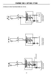
5.1 General schematic of the RC 400<br />
When the Scanreco RC 400 is installed an electrically controlled dump valve must, for<br />
reasons of safety, always be connected between the manoeuvre valve and the tank.<br />
This means that during an emergency stop manoeuvre the dump valve will be<br />
without power and will transfer the pump flow directly to the tank thus making the<br />
system entirely without hydraulic pressure.<br />
1<br />
5<br />
2<br />
4<br />
3<br />
6<br />
7 8<br />
Figure 5.1<br />
5.2 Important notice during welding<br />
Important: It is sometimes necessary to weld a truck/machine. During welding the<br />
system's electrical connections must always be disconnected from other equipment,<br />
i.e. power supply cables (+ and -), all valve contacts, the EX cables contact must be<br />
disconnected.<br />
5.3 Locating the central unit<br />
Important: The central unit must be mounted in accordance with the<br />
recommendations given below (see figure 5.2). To ensure the longest possible life for<br />
the central unit and its cables, the central unit must always be mounted so that the<br />
valve contacts are located facing downwards. The central unit must not be mounted<br />
so that the cables face upwards. The reason for this is to hinder water from running<br />
via the cables, towards the central unit<br />
(The cables on the central unit are thus not subjected to long periods of accumulated<br />
water, damp, salt etc). The central unit should be mounted in a vibration free<br />
location and not close to strong heat sources (for example exhaust pipes etc).
Document type Document number Rev Page<br />
<strong>Manual</strong> 66024 C 28 of 37<br />
Figure 5.2 How to mount the Central Unit.<br />
5.4 Mounting recommendations<br />
• For optimum radio communications the central unit and its antenna should be<br />
located as high and free as possible. An antenna screened and surrounded by<br />
fixed objects will considerably impair radio reception. An external antenna is<br />
available upon request.<br />
• The antenna pin must not touch any metal object.<br />
• The central unit should be mounted in a vibration free location and not be<br />
subjected to strong sources of heat (for example exhaust pipes etc).<br />
• Supply and valve cables should be mounted facing downwards!
Document type Document number Rev Page<br />
<strong>Manual</strong> 66024 C 29 of 37<br />
5.5 Cable kit assembly instruction<br />
In order to maximize product life and prevent involuntary service stops, this cable<br />
mounting guide should be consulted before attempting to assemble the cable kit.<br />
If grease is not already applied to the areas shown in the picture, be sure to add<br />
water resistant grease suitable for electronic applications in relevant quantities to the<br />
areas mentioned.<br />
Figure 5.3 Central unit with lid removed.
Document type Document number Rev Page<br />
<strong>Manual</strong> 66024 C 30 of 37<br />
Pierce the membrane and feed the cable through it. A tight fit ensures a good seal.<br />
Secure the cable with a tie strap or similar.<br />
Figure 5.4 Membrane.<br />
Figure 5.5 Tie strap.<br />
Apply grease as shown on the picture. Cover all exposed metal and fill all cavities.<br />
For best result, apply grease in the cavities on the connector prior to fitting the single<br />
wire connectors to it.<br />
Figure 5.6 Applied grease.<br />
Figure 5.7 Cable orientation.
Document type Document number Rev Page<br />
<strong>Manual</strong> 66024 C 31 of 37<br />
6 Trouble shouting (maintenance/fault<br />
finding)<br />
6.1 General information<br />
In the event of non-functionality:<br />
The operator can check the following before contacting the service workshop.<br />
The service workshop should check the following before distributor or Scanreco<br />
AB, Sweden, is contacted.<br />
Always check the Type- and Serial number on the related systems Portable Control<br />
Unit and Central Unit before distributor or Scanreco AB, Sweden, is contacted.<br />
6.2 Indications from the Portable Control Unit<br />
Status and alarm indications can be read from the Portable Control Units LED MICRO<br />
and LED ON and also via built in buzzer (see figure 6.1).<br />
1 = Left hand side of stop button; LED MICRO<br />
2 = Right hand side of stop button; LED ON<br />
3 = Sound, via internal buzzer<br />
1 2<br />
Figure 6.1 Status and alarm indication on portable control unit.
Document type Document number Rev Page<br />
<strong>Manual</strong> 66024 C 32 of 37<br />
6.2.1 Operational status indications<br />
The Portable Control Unit uses LED ON and LED MICRO to indicate current status and<br />
alarms.<br />
A functional system should indicate the following on LED ON:<br />
LED ON lit red; this means that the Portable Control Unit is active and transmitting<br />
data towards the Central Unit either via cable or radio.<br />
LED ON flashing red once every second; this means that the battery is<br />
approaching time for charging, this indication precedes by the buzzer that beeps<br />
three (3) times.<br />
LED MICRO is used to indicate current micro mode<br />
LED MICRO flashing green one, two, three, four or five times every third<br />
second; this means that the micro function is active, see chapter 3.3.6 for further<br />
information.<br />
6.2.2 Error codes<br />
During start-up of the Portable Central Unit a self test is conducted, any errors found<br />
are presented by an error code using ON LED and buzzer flashing/alarming a certain<br />
amount of times, the number of times represents a certain error:<br />
Indications<br />
1<br />
2<br />
3<br />
4<br />
5<br />
6<br />
7<br />
8<br />
Meaning<br />
Lever/Joystick at position 1 not in neutral position at start-up or<br />
defective<br />
Lever/Joystick at position 2 not in neutral position at start-up or<br />
defective<br />
Lever/Joystick at position 3 not in neutral position at start-up or<br />
defective<br />
Lever/Joystick at position 4 not in neutral position at start-up or<br />
defective<br />
Lever/Joystick at position 5 not in neutral position at start-up or<br />
defective<br />
Lever/Joystick at position 6 not in neutral position at start-up or<br />
defective<br />
Lever/Joystick at position 7 not in neutral position at start-up or<br />
defective<br />
Lever/Joystick at position 8 not in neutral position at start-up or<br />
defective<br />
13 Emergency stop failure during self test
Document type Document number Rev Page<br />
<strong>Manual</strong> 66024 C 33 of 37<br />
6.3 Indications on the Central Unit<br />
Status and error code indications can be read from the Central Units 2 front side<br />
LED’s (LED DV and LED STATUS) and thru lid window monitoring internal double 7-<br />
segment LED display, locations are displayed on below figure. (see figure 6.2).<br />
7-segment<br />
LED display<br />
STATUS LED`s<br />
Figure 6.2 Indicators on the Central Unit.<br />
6.3.1 Operational status indications<br />
Operational status indications can be read from the LED STATUS and LED DV.<br />
A functional system should indicate the following on LED ON:<br />
LED STATUS lit red; Central Unit is in standby mode<br />
LED STATUS lit green; Central Unit is in operational standby mode, or in<br />
operational mode<br />
LED STATUS flashing red; Error code sequence (Check double 7-segment LED<br />
display for further information.<br />
The LED DV is used to indicate current status for the Dump Valve output<br />
LED DV lit red; Indicates that the DV-output is active
Document type Document number Rev Page<br />
<strong>Manual</strong> 66024 C 34 of 37<br />
6.3.2 Error codes<br />
The Central Unit will indicate detected errors via the double 7-segment LED display.<br />
If the Central Unit detects an error it will be indicated by the LED STATUS flashing<br />
red whilst the the double 7-segment LED display indicates the error code with the<br />
digits “Er” followed by four digits in two blocks with the corresponding error code.<br />
Example on error code sequence:<br />
“Er” -> “15” ->”1A” -> ““Er” -> “15” ->”1A” ->“Er” -> “15” ->”1A” -><br />
The error code sequence will repeat itself three times if the error is considered a soft<br />
error and reboot to standby mode, if the error is considered a hard error the error<br />
code sequence will be continued until supply power is disconnected.<br />
Below list over error codes and their meaning<br />
Indication<br />
Meaning<br />
Block 1 Block 2<br />
01. 01-07 Checksum error (Block 2 declares type)<br />
02. 02 DV output short circuit<br />
04. 01-14 Digital output short circuit (Block 2 declares which<br />
output)<br />
07. 1A-8B Analog output error (Block 2 declares which output)<br />
15. 1A-8B Analog output short circuit (Block 2 declares which<br />
output)<br />
16. 1A-8B Analog output interruption (Block 2 declares which<br />
output)<br />
17. 01 Supply voltage too low<br />
17. 02 Supply voltage too high
Document type Document number Rev Page<br />
<strong>Manual</strong> 66024 C 35 of 37<br />
6.4 Non-functional system<br />
Always check the following:<br />
• Is there +12 VDC / +24 VDC, +/- 20 %, max. 5 %Vpeak to peak supply to the<br />
system? Measure at the emergency stop switch (unloaded and loaded).<br />
• Does the system operate via cable control function?<br />
• Does the system work manually, i.e. with the system in MANUAL mode?<br />
• Place switch into "REMOTE" position, check and verify how the Central Units<br />
LEDs and double 7-segment LED display indicate.<br />
• Activate Portable Control Unit, check and verify how the Portable Control Units<br />
LEDs and buzzer indicate.<br />
• Activate each available function one at a time, check and verify how the Central<br />
Units and/or Portable Control Unit indicate.
Document type Document number Rev Page<br />
<strong>Manual</strong> 66024 C 36 of 37<br />
7 Programming parameters and settings<br />
7.1 General description<br />
The Scanreco RC 400 offers considerable possibilities for system constructors of<br />
hydraulically driven mobile cranes and machines. The program in the control system<br />
is very comprehensive, flexible and has many adaptation possibilities for specific<br />
applications. The control system offers simple programming of a number of functions<br />
which can easily be turned on or off or altered during operation.<br />
To obtain the best manoeuvre characteristics in the simplest way, all programming /<br />
calibration of manoeuvre characteristics is made during operation (so called on-line).<br />
All programming / calibration are made from the portable control unit. Programming<br />
is simple and does not require tools / instruments.<br />
The control system is furnished with and prepared for 2-way (duplex)<br />
communications and for signal handling of functions such as ramp, parallel, lock,<br />
"dead-man's", hold, double and overload / lift reduction etc.<br />
The levels of authorisation are divided into four main groups:<br />
• Authorisation level 1 (Installer)<br />
• Authorisation level 2 (Well trained installer, well trained service personnel)<br />
• Authorisation level 3 (Well trained crane and valve manufacturer, well trained<br />
system constructor)<br />
• Authorisation level 4 (Scanreco AB, Sweden).
Document type Document number Rev Page<br />
<strong>Manual</strong> 66024 C 37 of 37<br />
7.2 Authorisation level 1<br />
7.2.1 Changing direction of movement<br />
This describes how changes in direction of movement are made if the crane moves in<br />
the opposite direction to that desired.<br />
Example:<br />
After installation and test operation it is found that the 3rd and 5th lever movements<br />
operate in the opposite direction to that desired. See the example below for how to<br />
change the 3rd and 5th lever movements.<br />
DO AS FOLLOWS<br />
1. Remove the battery pack. Connect the cable between the Portable Control<br />
Unit and Central Unit and test run the crane. Then press the stop button on<br />
the Portable Control Unit and emergency stop on the crane.<br />
2. Twist up the stop on the Portable Control Unit and on the crane.<br />
3. Press the Portable Control Unit's ON-button. The red LED should light<br />
continuously.<br />
4. Produce impulses in very quick succession with spring return switch MICRO to<br />
RIGHT in the OFF direction until the Portable Control Unit gives a long beep<br />
signal. Wait approx. 12 seconds until the next long beep signal then continue<br />
with no 5 below.<br />
Note 1. The red LED will be extinguished each time the Portable Control Unit<br />
gives a beep signal.<br />
Note. 2. If you do not receive the first long beep signal, start again from no 1<br />
above and execute no 3 and no 4. quicker. No 3 above and no 4. must be<br />
executed within max. 5 seconds.<br />
5. Now press ON-button once.<br />
The Portable Control Unit’s built-in beeper will give a short beep once every 5<br />
seconds to confirm that the items above have been done correctly. If any<br />
other beep signals are heard you must restart from item 1 again. Now you<br />
can easily change direction, see no 6 below.<br />
6. Now you can operate the crane. Move the 3rd control lever (which is<br />
operating in the opposite direction to that desired) and give switch MICRO an<br />
impulse to the LEFT in the ON direction.<br />
The crane will now change direction and continue with the same selected<br />
speed, in the opposite direction. Do the same with the 5th manoeuvre lever.<br />
Move the 5th manoeuvre lever (which is operating in the opposite direction to<br />
that which is desired) and give toggle switch MICRO an impulse to the LEFT in<br />
the ON direction. The crane will now immediately change direction and<br />
continue with the same selected speed in the opposite direction. If a direction<br />
change has been made earlier for a particular lever, do the same as above<br />
but give toggle switch MICRO an impulse to the RIGHT, in the OFF direction.<br />
Operate and check that all crane directions go in the desired direction.<br />
7. Press the stop button on the Portable Control Unit<br />
Programming is now completed and the crane is operating in the directions<br />
you decided in item 6. For radio operation, remove the cable control and test<br />
run the crane.<br />
If you are not satisfied with any direction/directions, repeat the above actions.
www.scanreco.se