You also want an ePaper? Increase the reach of your titles
YUMPU automatically turns print PDFs into web optimized ePapers that Google loves.
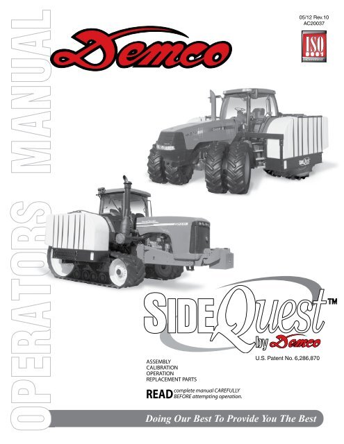
05/12 Rev.10<br />
<strong>AC20037</strong><br />
U.S. Patent No. 6,286,870<br />
Page 1
Thank you for purchasing <strong>Demco</strong>’s SIDEQUEST. We feel you have made a wise choice and hope you<br />
are completely satisfied with your SIDEQUEST. If you have any questions regarding the applications<br />
of certain solutions or chemicals, contact your chemical supplier and follow chemical manufacturer<br />
recommendations as well as all licensing and use restrictions or regulations.<br />
WARNING: To Avoid Personal Injury or Property Damage, Observe<br />
Following Instructions:<br />
Chemicals are dangerous. Know exactly what you’re going to do and what<br />
is going to happen before attempting to work with these products. Improper<br />
selection or use can injure people, animals, plants and soil.<br />
Always wear protective clothing such as coveralls, goggles and gloves when<br />
working with chemicals or sprayer.<br />
Be sure to dispose of all unused chemicals or solutions in a proper and<br />
ecologically sound manner.<br />
GENERAL INFORMATION<br />
1. Unless otherwise specified, high-strength (grade5)<br />
(3 radial-line head markings) hex head bolts are<br />
used throughout assembly of this sprayer.<br />
3. When placing a parts order, refer to this manual for<br />
proper part numbers and place order by PART NO.<br />
and DESCRIPTION.<br />
2. Whenever terms “LEFT” and “RIGHT” are used in<br />
this manual it means from a position behind sprayer<br />
and facing forward.<br />
Table of Contents<br />
General information............................................................................................................. 2<br />
Warranty Registration.........................................................................................................3-4<br />
Safety Information..............................................................................................................5-12<br />
Safety Sign Locations.......................................................................................................... 7<br />
Bolt Torque.......................................................................................................................... 13<br />
Assembly Instructions......................................................................................................... 14<br />
Parts Breakdown..............................................................................................................15-17<br />
Plumbing Breakdown.......................................................................................................... 16<br />
Optional Jack Stands Breakdown....................................................................................... 18<br />
Optional External Step Parts Breakdown and List.............................................................. 19<br />
Sprayer Checklist................................................................................................................ 20<br />
Page 2
4010 320th Street • Box 189 • Boyden, Iowa 51234<br />
Toll Free 800-54DEMCO (800-543-3626) • FAX 800-845-6420<br />
www.demco-products.com<br />
Warranty Registration<br />
Very<br />
Satisfied<br />
Satisfied<br />
Dissatisfied<br />
Ag<br />
RV<br />
Rental<br />
Brakes<br />
Marine<br />
m<br />
m<br />
m<br />
m<br />
m<br />
Very<br />
Dissatisfied<br />
How satisfied are you with our product? m m m m<br />
How satisfied are you with the dealership/distributor sales staff? m m m m<br />
Dealer/Distributor Name City State<br />
How satisfied are you with the company sales staff? m m m m<br />
How satisfied are you with the delivery? m m m m<br />
Did you have any contact with a <strong>Demco</strong> Representative? YES NO<br />
If YES, how satisfied were you? m m m m<br />
I would recommend this product to my family and friends. YES NO<br />
Would you purchase again from DEMCO? YES NO<br />
Since taking delivery, have you been contacted by the dealer? YES NO<br />
Did you have any problems with this DEMCO product? YES NO<br />
If YES, are you satisfied with the company’s resolution of your problem? m m m m<br />
Please list the specific source of information prompting this purchase.<br />
After purchasing this product, do you see any needed product improvement?<br />
If yes, what improvement?<br />
What other products would you like to see DEMCO offer?<br />
Comments<br />
Owner’s Name:<br />
Mailing Address:<br />
City: State: Zip Code:<br />
Model#:<br />
Serial #:<br />
Purchase Date:<br />
Owner’s Signature:<br />
Please return to DEMCO By FAX or tri-folding this form to Page the backside, 3 it is pre-addressed.
Postage<br />
<strong>Demco</strong><br />
4010 320th Street, Box 189<br />
Boyden, Iowa 51234<br />
Page 4
SAFETY<br />
TAKE NOTE! THIS SAFETY ALERT SYMBOL FOUND THROUGHOUT THIS<br />
MANUAL IS USED TO CALL YOUR ATTENTION TO INSTRUCTIONS INVOLVING<br />
YOUR PERSONAL SAFETY AND SAFETY OF OTHERS. FAILURE TO FOLLOW<br />
THESE INSTRUCTIONS CAN RESULT IN INJURY OR DEATH.<br />
THIS SYMBOL MEANS<br />
ATTENTION<br />
BECOME ALERT<br />
YOUR SAFETY IS INVOLVED!<br />
SIGNAL WORDS<br />
Note: use of the following signal words DANGER,<br />
WARNING, and CAUTION with safety messages.<br />
Appropriate signal word for each has been selected<br />
using following guidelines:<br />
DANGER:<br />
Indicates an imminently hazardous situation that,<br />
if not avoided, will result in death or serious injury.<br />
This signal word is to be limited to most extreme<br />
situations typically for machine components which,<br />
for functional purposes, cannot be guarded.<br />
warning:<br />
Indicates a potentially hazardous situation that, if<br />
not avoided, could result in death or serious injury,<br />
and includes hazards that are exposed when<br />
guards are removed. It may also be used to alert<br />
against unsafe practices.<br />
caution:<br />
Indicates a potentially hazardous situation that,<br />
if not avoided, may result in minor or moderate<br />
injury. It may also be used to alert against unsafe<br />
practices.<br />
If you have questions not answered in this manual, require additional copies, or if your manual is damaged,<br />
please contact your dealer or <strong>Demco</strong> P.O. Box 189, 4010 320th Street, Boyden, IA 51234<br />
ph: (712) 725-2311 or (712) 725-2302 Toll Free: 1-800-543-3626 Fax: (712) 725-2380<br />
http://www.demco-products.com<br />
Page 5
SAFETY...you can live with it<br />
Equipment safety guidelines<br />
Every year many accidents occur which could be avoided by a few seconds of thought and<br />
more careful approach to handling equipment. You, the operator, can avoid accidents by<br />
observing precautions in this section. To avoid personal injury, study precautions and insist<br />
those working with you, or you yourself, follow them.<br />
In order to provide a better view, certain illustrations in this manual may show an assembly<br />
with a safety shield removed. However, sprayer should never be operated in this condition.<br />
Keep all shields in place. If shield removal becomes necessary for repairs, replace shield<br />
prior to use.<br />
Replace any caution, warning, danger or instruction safety decal that is not readable or is<br />
missing. Location of such decals is indicated in this booklet.<br />
Do not attempt to operate this sprayer under the influence of alcohol or drugs.<br />
Review safety instructions with all users.<br />
Operator should be a responsible adult. Do not allow persons to operate or<br />
assemble this sprayer until they have developed a thorough understanding<br />
of safety precautions and how it works.<br />
To prevent injury or death, use a tractor equipped with a roll over protective system (ROPS).<br />
Do not paint over, remove, or deface any safety signs or warning decals on your sprayer.<br />
Observe all safety signs and practice instructions on them.<br />
Never exceed limits of sprayer. If its ability to do a job, or to do so safely is in question<br />
don’t try it.<br />
Lighting and marking<br />
It is the responsibility of operator to know lighting and marking requirements of local highway<br />
authorities and to install and maintain equipment to provide compliance with regulations.<br />
Add extra lights when transporting at night or during periods of limited visibility.<br />
Lighting kits are available from your dealer or manufacturer.<br />
Page 6
SAFETY SIGN LOCATIONS<br />
Part# 10328 Red<br />
(on back side of tank)<br />
WARNING<br />
To prevent serious injury or death<br />
• Refer to chemical supplier and manufacturer recommendations and all<br />
licensing restrictions or regulations.<br />
• Always wear recommended protective clothing when working with chemicals or<br />
sprayer.<br />
• Dispose of all unused chemicals or solutions in proper and ecologically<br />
sound manner. Improper use can injure people, animals, plants and soil.<br />
REv 1<br />
AB21014<br />
WARNING<br />
Ab21014<br />
To prevent serious injury or<br />
death.<br />
Do not ride or stand on sprayer<br />
while any part of sprayer is<br />
moving.<br />
Keep riders off at all times.<br />
REv 1<br />
Ab21001<br />
AB21001<br />
WARNING<br />
To prevent serious injury or death<br />
• Store sprayer on hard level surface.<br />
• Store empty.<br />
REV 1<br />
AB21002<br />
AB21002<br />
Part# 10327 Amber<br />
Page 7
Safety sign care<br />
• Keep safety signs clean and legible at all times.<br />
• Replace safety signs that are missing or have become illegible.<br />
• Replacement parts that displayed a safety sign should also display current sign.<br />
• Safety signs are available from your distributor, dealer parts department, or manufacturer.<br />
How to install safety signs:<br />
• Be sure installation area is clean and dry.<br />
• Decide on exact position before you remove backing paper.<br />
• Remove smallest portion of split backing paper.<br />
• Align decal over specified area and carefully press small portion with<br />
exposed sticky backing in place.<br />
• Slowly peel back remaining paper and carefully smooth remaining portion of<br />
decal into place.<br />
• Small air pockets can be pierced with a pin and smoothed out using piece of decal<br />
backing paper.<br />
Tire safety<br />
• Failure to follow proper procedures when mounting tire on rim can produce an<br />
explosion resulting in serious injury or death.<br />
• Do not attempt to mount tire unless you have proper equipment and experience.<br />
• Inflating or servicing tires can be dangerous. Whenever possible, trained personnel<br />
should be called to service or mount tires.<br />
• Always order and install tires and wheels with appropriate type and load capacity to<br />
meet or exceed anticipated weight to be placed on sprayer.<br />
Remember<br />
Your best assurance against accidents is a careful and responsible operator. If there is any<br />
portion of this manual or function you do not understand, contact your local authorized dealer<br />
or manufacturer.<br />
Before operation:<br />
• Carefully study and understand this manual.<br />
• Do not wear loose-fitting clothing which may catch in moving parts.<br />
• Always wear protective clothing and substantial shoes.<br />
• It is recommended that suitable hearing and eye protection be worn.<br />
• Operator may come in contact with certain materials which may require specific safety<br />
equipment relative to handling of such materials. (Examples: extremely dust, molds,<br />
fungus, bulk fertilizers, etc.)<br />
Page 8
• Keep wheel and lug nuts tightened to specified torque.<br />
• Assure that agricultural implement tires are inflated evenly.<br />
• Give sprayer a visual inspection for any loose bolts, worn parts, or cracked welds, and make<br />
necessary repairs. Follow maintenance safety instructions included in this manual.<br />
• Be sure there are no tools lying on or in equipment.<br />
• Do not use the sprayer until you are sure that area is clear, especially around children and<br />
animals.<br />
• Don’t hurry learning process or take sprayer for granted. Ease into it and become familiar<br />
with your new equipment.<br />
• Practice operation of your sprayer and its attachments. Completely familiarize yourself<br />
and other operators with its operation before using.<br />
• Use a tractor equipped with Roll Over Protection System (ROPS) and fasten your seat belt<br />
prior to starting engine.<br />
• Manufacturer does not recommend usage of tractor with ROPS removed.<br />
• Move tractor wheels to widest recommended settings to increase stability.<br />
• Do not allow anyone to stand between tongue or hitch and towing unit when backing<br />
up to equipment.<br />
During operation<br />
• Beware of bystanders, PARTICULARLY CHILDREN! Always look around to make sure it is<br />
safe to start engine of towing unit or move sprayer. This is particularly important with higher<br />
noise levels and quiet cabs, as you may not hear people shouting.<br />
• NO PASSENGERS ALLOWED- Do not carry passengers anywhere on or in the tractor or<br />
sprayer.<br />
• Keep hands and clothing clear of moving parts.<br />
• Do not clean, lubricate, or adjust your sprayer while it is moving.<br />
• When halting operation, even periodically, set tractor or towing unit brakes, disengage<br />
PTO, shut off engine, and remove ignition key.<br />
• Be especially observant of operating area and terrain- watch for holes, rocks, or other hidden<br />
hazards. Always inspect area prior to operation.<br />
- DO NOT operate near edge of drop-offs or banks.<br />
- DO NOT operate on steep slopes as overturn may result.<br />
- Operate up and down (not across) intermediate slopes. Avoid sudden starts and stops.<br />
Page 9
• Pick the most level possible route when transporting across fields. Avoid edges of ditches,<br />
gullies, and steep hillsides.<br />
• Be extra careful when working on inclines.<br />
• Periodically clear equipment of brush, twigs, or other materials to prevent buildup of dry<br />
combustible materials.<br />
• Maneuver tractor or towing unit at safe speeds.<br />
• Avoid overhead wires or other obstacles. Contact with overhead lines could cause serious<br />
injury or death.<br />
• Avoid loose gravel, rocks, and holes; they can be dangerous for equipment operation or<br />
movement.<br />
• Allow for sprayer length when making turns.<br />
• Do not walk or work under raised components or attachments unless securely positioned and<br />
blocked.<br />
• Keep all bystanders, pets, and livestock clear of work area.<br />
• Operate towing unit from operators seat only.<br />
• Never stand alongside of unit with engine running or attempt to start engine and/or operate<br />
machine while standing alongside of unit.<br />
• Never leave running equipment attachments unattended.<br />
• As a precaution, always recheck hardware on equipment following every 100 hours of<br />
operation. Correct all problems. Follow maintenance safety procedures.<br />
Following operation<br />
• Following operation, or when unhitching, stop tractor or towing unit, set brakes, disengage<br />
PTO and all power drives, shut off engine and remove ignition key.<br />
• Store sprayer in an area away from human activity.<br />
• Do not park sprayer where it will be exposed to livestock for long periods of time. Damage and<br />
livestock injury could result.<br />
• Do not permit children to play on or around the stored sprayer.<br />
• Make sure all parked machines are on a hard, level surface and engage all safety devices.<br />
• Wheel chocks may be needed to prevent unit from rolling.<br />
Page 10
Highway and transport operations<br />
• SAFETY CHAINS: If equipment is going to be transported on a public highway, always<br />
follow state and local regulations regarding safety chains and auxiliary lighting. Be sure to<br />
check with local law enforcement agencies for your own particular regulations. If required<br />
safety chains should be obtained and installed. Only safety chains (not elastic or nylon/plastic<br />
tow straps) should be used to retain connection between towing and towed machines in event<br />
of separation of primary attaching system. Use a high strength, appropriately sized hitch pin<br />
with a mechanical retainer and attach safety chains. Criss cross chains under tongue and<br />
secure to draw bar cage, mounting loops, or bumper frame.<br />
• Adopt safe driving practices:<br />
- Keep brake pedals latched together at all times. NEVER USE INDEPENDENT BRAKING<br />
WITH SPRAYER IN TOW. LOSS OF CONTROL OR UPSET MAY RESULT.<br />
- Always drive at a safe speed relative to local conditions and ensure that your speed is low<br />
enough for an emergency stop. Keep speed to a minimum.<br />
- Reduce speed prior to turns to avoid risk of overturning.<br />
- Always keep tractor or towing unit in gear to provide engine braking when going<br />
downhill. Do not coast.<br />
- Do not drink and drive!<br />
• Comply with state and local laws governing highway safety and movement of farm machinery on<br />
public roads.<br />
• Use approved accessory lighting flags and necessary warning devices to protect operators of<br />
other vehicles on highway during transport. Various safety lights and devices are available<br />
from your dealer.<br />
• Use of flashing amber lights is acceptable in most localities. However, some localities prohibit<br />
their use. Local laws should be checked for all highway lighting and marking requirements.<br />
• When driving tractor and sprayer under 20 mph (40 kph) day or night, use flashing amber warning<br />
lights and a slow moving vehicle (SMV) identification emblem.<br />
• Plan your route to avoid heavy traffic.<br />
• Be a safe and courteous driver. Always yield to oncoming traffic in all situations, including narrow<br />
bridges, intersections, etc.<br />
• Be observant of bridge load ratings. Do not cross bridges rated lower than gross weight of unit<br />
you are operating.<br />
Page 11
• Watch for obstructions overhead and side to side while transporting.<br />
• Always operate equipment in a position to provide maximum visibility at all times. Make<br />
allowances for increased length and weight of sprayer when making turns, or stopping.<br />
Performing maintenance<br />
• Good maintenance is your responsibility. Poor maintenance is an invitation to trouble.<br />
• Make sure there is plenty of ventilation. Never operate engine of towing vehicle in<br />
a closed building. Exhaust fumes may cause asphyxiation.<br />
• Before working on this machine, stop towing vehicle, set brakes, disengage PTO<br />
and all power drives, shut off engine and remove ignition key.<br />
• Be certain all moving parts and attachments have come to a complete stop before<br />
attempting to perform maintenance.<br />
• Always use a safety support and block wheels. Never use a jack to support machine.<br />
• Always use proper tools or equipment for job at hand.<br />
• Use extreme caution when making adjustments.<br />
• Follow torque chart in this manual when tightening bolts and nuts.<br />
• Never use your hands to locate a hydraulic leak on attachments. Use a small piece of<br />
cardboard or wood. Hydraulic fluid escaping under pressure can penetrate skin.<br />
• Openings in skin and minor cuts are susceptible to infection from hydraulic fluid.<br />
Without immediate medical treatment, serious infection and reactions can occur.<br />
• When disconnecting hydraulic lines, shut off hydraulic supply and relieve all hydraulic<br />
pressure.<br />
• Replace all shields and guards after servicing and before moving.<br />
• After servicing, be sure all tools, parts and service equipment are removed.<br />
• Do not allow grease or oil to build up on any steps or platform.<br />
• When replacing bolts refer to owners manual.<br />
• Refer to bolt torque chart for head identification marking.<br />
• Where replacement parts are necessary for periodic maintenance and servicing,<br />
genuine factory replacement parts must be used to restore your equipment to original<br />
specifications. Manufacturer will not claim responsibility for use of unapproved parts or<br />
accessories and other damages as a result of their use.<br />
• If equipment has been altered in any way from original design, manufacturer does<br />
not accept any liability for injury or warranty.<br />
• A fire extinguisher and first aid kit should be kept readily accessible while performing<br />
maintenance on this equipment<br />
Page 12
BOLT TORQUE<br />
TORQUE DATA FOR STANDARD NUTS, BOLTS, AND CAPSCREWS.<br />
Tighten all bolts to torques specified in chart unless otherwise noted. Check tightness of bolts<br />
periodically, using bolt chart as guide. Replace hardware with same grade bolt.<br />
NOTE: Unless otherwise specified, high-strength Grade 5 hex bolts are used throughout<br />
assembly of equipment.<br />
Bolt Torque for Standard bolts *<br />
Torque Specifications<br />
GRADE 2 GRADE 5 GRADE 8<br />
“A” lb-ft (N.m) lb-ft (N.m) lb-ft (N.m)<br />
1/4” 6 (8) 9 (12) 12 (16)<br />
5/16” 10 (13) 18 (25) 25 (35)<br />
3/8” 20 (27) 30 (40) 45 (60)<br />
7/16” 30 (40) 50 (70) 80 (110)<br />
1/2” 45 (60) 75 (100) 115 (155)<br />
9/16” 70 (95) 115 (155) 165 (220)<br />
5/8” 95 (130) 150 (200) 225 (300)<br />
3/4” 165 (225) 290 (390) 400 (540)<br />
7/8” 170 (230) 420 (570) 650 (880)<br />
1” 225 (300) 630 (850) 970 (1310)<br />
Bolt Torque for Metric bolts *<br />
Torque figures indicated are valid for<br />
non-greased or non-oiled threads and<br />
heads unless otherwise specified.<br />
Therefore, do not grease or oil bolts or<br />
capscrews unless otherwise specified<br />
in this manual. When using locking<br />
elements, increase torque values<br />
by 5%.<br />
* GRADE or CLASS value for bolts<br />
and capscrews are identified by their<br />
head markings.<br />
CLASS 8.8 CLASS 9.8 CLASS 10.9<br />
“A” lb-ft (N.m) lb-ft (N.m) lb-ft (N.m)<br />
6 9 (13) 10 (14) 13 (17)<br />
7 15 (21) 18 (24) 21 (29)<br />
8 23 (31) 25 (34) 31 (42)<br />
10 45 (61) 50 (68) 61 (83)<br />
12 78 (106) 88 (118) 106 (144)<br />
14 125 (169) 140 (189) 170 (230)<br />
16 194 (263) 216 (293) 263 (357)<br />
18 268 (363) -- -- 364 (493)<br />
20 378 (513) -- -- 515 (689)<br />
22 516 (699) -- -- 702 (952)<br />
24 654 (886) -- -- 890 (1206)<br />
GRADE-2 GRADE-5 GRADE-8 CLASS 8.8 CLASS 9.8 CLASS 10.9<br />
A<br />
8.8 9.8 10.9<br />
Page 13
Assembly Instructions For 10-Bolt Hub<br />
Preparation: Remove any loader brackets from the tractor. The<br />
tractor duals must be set to 120” wheel spacing. Mount base<br />
plate (specific to your tractor model) to the side of the tractor. See<br />
separate instruction found in base plate parts box.<br />
1. With proper hydraulic jack, lift tractor until weight is off dual wheel<br />
but still touching ground. Be sure to secure wheel properly.<br />
Remove all lug bolts on the tractor’s dual as shown in VIEW A.<br />
2. Bolt the Hub Spacer to the tractor’s dual:<br />
• VIEW A - Bolt the Hub Spacer to the tractor’s dual using (10) #33<br />
Hex Hd. Bolts and Tractor’s original washers. Bolt the Hub/Spindle<br />
Assembly to the Hub Spacer using (10) #35 and (10) #16 Wheel<br />
Nuts.<br />
• VIEW B - Bolt the Hub Spacer to the tractor’s dual using (10) #29<br />
D-head Studs and Tractor’s original wheel nuts. Bolt the Hub/<br />
Spindle Assembly to the Hub Spacer using (10) #32 and (10) #4<br />
Lockwashers.<br />
• Torque all bolts to the specifications found in this manual.<br />
31<br />
16<br />
VIEW A<br />
35<br />
34<br />
10<br />
33<br />
3. Before installing tank assemblies onto the Hub/Spindle, determine<br />
which height setting is desirable. Slide the tank assembly over the<br />
spindle as shown in VIEW C. Make sure the arrow on the end of the<br />
ITEM PART # DESCRIPTION QTY<br />
* 9445213 WHEEL 46" X 10A, 10 BOLT 1<br />
8 02534<br />
WASHER, MACHINE, .75 X 14GA NR(<br />
PLATED)<br />
10<br />
12 07435 3/4" UNF WHEEL NUT 10<br />
23 13216-35 HUB/SPINDLE F/ SIDEQUEST 10 BOLT 1<br />
25 10284 BOLT .875NF X 2.00 GR5 HEX 10<br />
spindle is always pointing up as shown. Slide the tank assembly<br />
in until there is a spacing of approximately 2” between the tire and<br />
the tank assembly. Use (4) #15 set screws to hold the spindle in<br />
place. Turn the set screws into the threaded inserts on the outside<br />
of the tube the spindle has been placed in.<br />
26 13258 CAST HUB SPACER 10 BOLT 1<br />
27 13568 BOLT .75NF X 3.00 GR5 HEX ZNC 10<br />
4. Install Extension Arm #26 to the tractor base plate on P. 17. using<br />
(1) #27 Pin and (2) #12 Lynch Pins.<br />
4010 320TH ST. PO BOX 189<br />
BOYDEN, IOWA 51234<br />
THE DRAWING AND ALL<br />
INFORMATION THERE<br />
ON ARE THE PROPERTY OF<br />
DEMCO<br />
32<br />
4<br />
DRAWN BY<br />
BVDP<br />
DATE<br />
09/14/09<br />
ENG APPOV.<br />
PK<br />
DATE<br />
11/17/09<br />
30<br />
UNLESS OTHERWISE<br />
SPECIFIEDALL DIMENSIONS<br />
THIRD ANGLE<br />
ARE IN INCHES<br />
PROJECTION<br />
TOLERANCES<br />
.X = .060 MIN. MACHINE SUFACE 250<br />
.XX = ±.030 BREAK ALL SHARP EDGES<br />
.XXX = ±.010 BEND AND DRAFT ±1°<br />
14<br />
29<br />
DESCRIPTION<br />
10 BOLT ASSEMBLY<br />
003233RD<br />
DRAWING. NO.<br />
SCALE: 1:18<br />
SHEE<br />
5. Slide the fixed or adjustable tank hanger bracket #23 or #25 onto the<br />
extension arm. Bolt channels #15 or #24 to front of tank assembly.<br />
For tractor’s with adjustable channels #24, bolt to the tube slide<br />
box #25. Install set screws. Torque all bolts to the specifications<br />
found in this manual.<br />
6. Repeat same instructions for the opposite side.<br />
NOTE:<br />
View A, B, & C use parts list on next page.<br />
ITEM PART # DESCRIPTION QTY<br />
4 00254 .75"-LOCKWASHER 10<br />
10 07435 3/4" UNF WHEEL NUT 10<br />
21 13024 Bolt, 22mm x 100mm D-head Stud 10<br />
22 13211 16.125 HUB SPACER 1<br />
23 13216-35 HUB/SPINDLE F/ SIDEQUEST 10 BOLT 1<br />
24 13217 BOLT, .75 NF X 2.50 HEX HEAD GR. 5 10<br />
7 9445213 WHEEL 46" X 10A, 10 BOLT 1<br />
To prevent serious injury or death<br />
On John Deere tractors check hub thickness.<br />
If thickness is greater than 2.31” standard<br />
bolts will fail.<br />
13586 Hex Bolt 22MM-2.50 x 140 MM GR. 10.9<br />
must be used.<br />
REV 0<br />
WARNING<br />
AC21005<br />
Page 14<br />
31<br />
VIEW B Agco only.<br />
4010 320TH ST. PO BOX 189<br />
BOYDEN, IOWA 51234<br />
THE DRAWING AND ALL<br />
INFORMATION THERE<br />
ON ARE THE PROPERTY OF<br />
DEMCO<br />
VIEW C<br />
15<br />
DRAWN BY<br />
ENG APPOV.<br />
BVDP<br />
PK<br />
DATE<br />
DATE<br />
UNLESS OTHERWISE<br />
SPECIFIEDALL DIMENSIONS<br />
THIRD ANGLE<br />
ARE IN INCHES<br />
PROJECTION<br />
10/14/08<br />
11/17/09<br />
TOLERANCES<br />
.X = .060 MIN. MACHINE SUFACE 250<br />
.XX = ±.030 BREAK ALL SHARP EDGES<br />
.XXX = ±.010 BEND AND DRAFT ±1°<br />
15<br />
DESCRIPTION<br />
10 BOLT ASSEMBLY<br />
003215RD<br />
DRAWING. NO.<br />
SCALE: 1:18<br />
31<br />
SHEE
Ref. Part<br />
No. No. Qty. Description<br />
1. 00083 8 1/2”-UNC Hex Hd. Nut<br />
2. 00084 14 1/2” Lockwasher<br />
3. 00085 20 1/2” Flatwasher<br />
4. 00254 20 3/4” Lockwasher<br />
5. 00482 8 1/2”-UNC x 1-3/4” Gr.5 Hex Hd. Bolt<br />
6. 00640 8 1/2”-UNC Jam Nut<br />
7. 00967 16 1/2”-UNC x 1-1/4” Gr.5 Hex Hd. Bolt<br />
8. 01253 6 1/2”-UNC x 2” Gr. 5 Hex Head Bolt<br />
9. 01254 14 1/2”-UNC x 1-1/2” Gr.5 Hex Hd. Bolt<br />
10. - - Original Tractor Washers<br />
11. 02178 16 1/2”-UNC Nylon Lock Nut<br />
12. 02397 4 Lynch Pin<br />
13. 02592 16 3/8”-UNC Nylon Insert Locknut<br />
14. - - Wheel Nuts from Tractor’s Duals<br />
15. 06102 12 Set Screw 1/2” x 1-1/4” Cup Point<br />
16. 07435 - 3/4”-NF Wheel Nut<br />
17. 10214-35 16 Tank Hold Down (350 gal. ONLY)<br />
18. 10215-35 2 Tank Hold Down (500 gal. ONLY)<br />
19. 10245 8 Cable Assembly<br />
20. 10918-35 2 Top Angle Support (500 gal. ONLY)<br />
21. 10923-35 3 Support Crossbar (500 gal. ONLY)<br />
SIDEQUEST PARTS BREAKDOWN<br />
22. 10924-35 12 Tank Support Tube (500 gal. ONLY)<br />
23. 11442-35 4 Hanger Bracket<br />
24. 13022-35 4 Drop Channel<br />
25. 13023-35 4 Tube Slide Box<br />
26. 11644-35 2 Mounting Extension Arm, 30”<br />
- 12001-35 2 Mounting Extension Arm, 36”<br />
27. 11651-95 2 Upper Pin<br />
28. 12330-35 2 Tank Carrier<br />
29. 13024 16 Agco Bolt 22mm x 100mm D-Head Stud<br />
30. 13211 2 10 Bolt Hub Spacer<br />
31. 13216-35 2 Spindle/Hub Assembly<br />
- 13215 - Spindle Only<br />
32. 13217 20 3/4”-NF x 2-1/2” Gr.5 Hex Hd Bolt<br />
33. 13222 16 Bolt, 22MM-2.50 x 120MM Gr10.9<br />
John Deere, Case IH MX Magnum &<br />
TG New Holland<br />
- 13586 16 Bolt, 22MM-2.50 x 140MM Gr 10.9<br />
John Deere Heavy Duty<br />
- 13587 16 Bolt, .875-9 x 4.00 Gr 8 Case IH 71,<br />
72 & 89<br />
- 13588 16 Bolt, .875NF x 4.00 Gr 8 Ford Genesis<br />
34. 13775-35 2 10 Bolt Cast Hub Spacer<br />
35. 13568 20 3/4”-NF x 3” Gr.5 Hex Head Bolt<br />
NOTE:<br />
Refer to this parts list for parts<br />
shown on pages 14,16-17.<br />
A<br />
B<br />
C<br />
d<br />
5902 Hub Breakdown<br />
Ref. Part<br />
No. No. Qty. Description<br />
A. 13214 1 Oil Seal<br />
B. 13624 1 Inner Cone Bearing, Timken<br />
C. 13626 1 Inner Cup, Timken<br />
D. 13629 1 Hub, includes Inner/Outer Cups<br />
E. 13627 1 Outer Cup, Timken<br />
F. 13625 1 Outer Cone Bearing, Timken<br />
G. 09532 1 Hub Cap Gasket<br />
H. 07362 1 Hub Cap<br />
I. 04305 4 5/16” x 1/2” Hex Head Bolt<br />
J. 07354 1 3” x 1-21/64” x 3/16” Washer<br />
K. 07353 1 1-1/4”NF Castle Nut<br />
L. 05088 1 3/16” x 2-1/2” Cotter Pin<br />
e<br />
l<br />
*Items J,K, and L are shown<br />
for reference only and are not<br />
included in hub assembly.<br />
f<br />
j<br />
k<br />
g<br />
h<br />
i<br />
Page 15
350 GALLON SIDEQUEST CENTER EXIT PARTS BREAKDOWN<br />
19<br />
13<br />
17<br />
15 <br />
23<br />
16<br />
31<br />
35<br />
34<br />
28<br />
3<br />
2<br />
9<br />
15<br />
10<br />
33<br />
1<br />
2<br />
TANK BREAKDOWN<br />
26<br />
5<br />
Ref. Part<br />
No. No. Qty. Description<br />
--. P350WA 2 350 gallon Tank Assy (white)<br />
--. P350A 2 350 gallon Tank Assy (yellow)<br />
--. P500WA 2 500 gallon Tank Assy (white)<br />
--. P500A 2 500 gallon Tank Assy (yellow)<br />
P1. 09941 1 Agitator Jet<br />
P2. 10267 1 Siphon Tube<br />
P3. BRB1034 1 1” MPT to 3/4” FPT Reducer Bushing<br />
P4. FTF100 1 1” Flanged Tank Fitting<br />
P5. FTF200 1 2” Flanged Tank Fitting<br />
* When ordering replacement tanks, please specify if<br />
the tank you need is either a right or left or center and/<br />
or yellow or white.<br />
* Items P1, P2, P3, P4, and P5 included when ordering<br />
the tank assy<br />
NOTE:<br />
Refer to p.15 for replacement part numbers.<br />
NOTE: All units will attach<br />
elbow fittings here.<br />
p1<br />
p2<br />
p3<br />
p4<br />
p5<br />
Page 16
500 GALLON SIDEQUEST CENTER EXIT PARTS BREAKDOWN<br />
21<br />
20<br />
22<br />
2 8 3<br />
2 9<br />
22<br />
19<br />
13<br />
18<br />
22<br />
15<br />
23<br />
28<br />
3<br />
2<br />
9<br />
15<br />
25<br />
16<br />
31<br />
35<br />
1<br />
2<br />
26<br />
5<br />
15 7 11<br />
6<br />
34<br />
10<br />
33<br />
24<br />
26<br />
NOTE:<br />
Refer to p.15 for replacement part numbers.<br />
Page 17<br />
27<br />
12<br />
12
OPTIONAL SIDEQUEST JACK STANDS BREAKDOWN<br />
Notes:<br />
Adjustable jack may be used in two locations.<br />
On the outside of the Stand Mount Bracket<br />
as well as in the rear of the Tank holder.<br />
Ref. Part<br />
No. No. Qty. Description<br />
1. 07551-35 4 Wheel Stand<br />
2. 10199-35 2 Stand Mounting Bracket<br />
3. 10243 2 Caster Wheel Assembly<br />
4. 10244-35 2 Adjustable Jack Assembly<br />
5. 00182 2 Hair Pin, 7 gauge<br />
6. 00477 8 5/8” Flatwasher<br />
7. 00489 4 5/8”-UNC Jam Nut<br />
8. 01718-95 4 Lock pin<br />
9. 02496 4 5/8”-UNC x 4” Hex Hd Bolt Gr.5<br />
10. 02587 4 5/8”-UNC Nylon Insert Locknut<br />
11. 04445 4 6” x 2” Black Wheel with bushing<br />
12. 00060 6 3/8” Lockwasher<br />
13. 00061 6 3/8”-UNC Hex Hd. Nut<br />
14. 00907 6 3/8”-UNC x 1” Hex Hd. Bolt Gr.5<br />
14<br />
8<br />
1 2<br />
5<br />
12<br />
13<br />
9<br />
6<br />
11<br />
6<br />
7<br />
10<br />
4<br />
3<br />
Page 18
Optional SideQuest Fold-away External Step PARTS BREAKDOWN<br />
Rear of Tractor<br />
4<br />
5<br />
10<br />
Front of Tractor<br />
Step Parts Breakdown<br />
7<br />
REF.<br />
NO.<br />
PART<br />
NO. QTY. DESCRIPTION<br />
1. 11446-35 2 External Step<br />
2. 11447-35 2 Left Step Support<br />
3<br />
3. 11448-35 2 Left Step Mount<br />
4. 11449-35 2 Right Step Mount<br />
5. 11450-35 2 Right Step Support<br />
6. 00059 20 3/8” Flatwasher<br />
7. 00523 16 3/8” x 1-1/4” Hex Head Bolt (Gr. 5)<br />
8. 02592 16 3/8” Nylon Insert Locknut<br />
9. 07919-95 8 Bushing<br />
10. 11451 4 Support Cable<br />
11. 10219-35 1 Tank Carrier (Not Included w/Kit)<br />
Please order replacement parts by PART NO. and DESCRIPTION.<br />
11<br />
7<br />
6<br />
9<br />
7<br />
7<br />
8<br />
3<br />
8<br />
6<br />
8<br />
7<br />
10<br />
6<br />
2<br />
9<br />
7<br />
6<br />
8<br />
8<br />
NOTE: TO ADJUST ANGLE OF STEP<br />
ADJUST THE CABLES TOP BOLT<br />
TO ONE OF 3 HOLE POSITIONS.<br />
1<br />
NOTE: Part quantities are for both sides, but<br />
only one side is shown.<br />
Page 19
SPRAYER CHECKLIST:<br />
Downtime caused by field breakdowns is costly and time consuming. Many breakdowns can be<br />
eliminated by periodic equipment maintenance. By spending time reviewing this checklist before<br />
seasonal spraying application time and following proper after season care, you can save time<br />
and money later.<br />
Warning: To Prevent Serious Injury Or Death<br />
• Keep hands, feet, and loose clothing away from rotating parts.<br />
• Wear protective clothing recommended by your chemical and<br />
fertilizer manufacturer when working with chemicals.<br />
Check Before Going To The Field :<br />
1. NOZZLES<br />
Check tip for excessive wear by checking for grooves in<br />
or near tip opening. Check nozzle spacing by starting<br />
at center and working outwards. Check boom for proper<br />
height.<br />
2. HOSES<br />
Check all hoses for worn or soft spots. Be sure all hose<br />
clamps are tightened and hoses are not kinked or pinched.<br />
Check for leakage in any lines.<br />
3. TANK<br />
Remove and clean agitator orifices. Check orifices for<br />
excessive wear by checking for grooves in or near orifice<br />
opening. Inspect fitting and grommets to insure they are<br />
in good condition.<br />
4. CONTROLS<br />
Check for leakage, plugging, or wear on all valves, fittings,<br />
etc. Clean off any build up of foreign material.<br />
5. PUMP<br />
Check to be sure pump turns freely.<br />
6. FRAME<br />
Be sure all bolts are tightened.<br />
7. REPLACEMENT PARTS<br />
Replace all worn or damaged parts.<br />
After Season Care:<br />
NOTE: It is important to wear proper safety equipment<br />
when cleaning the SIDEQUEST . See your<br />
chemical or fertilizer package for this information.<br />
1. After spraying chemicals, run water mixed with cleaners<br />
through tank, pump and all hose hookups. If wettable<br />
powder dries out in the system, it is very difficult to put<br />
back into suspension and can cause malfunction,<br />
damage or injury.<br />
2. When cleaned, tank should have all openings closed<br />
or covered to keep dirt from entering.<br />
3. Pump should be flushed with soluble oil and pump ports<br />
plugged to keep out moisture and air.<br />
4. Disassemble tips and rinse with water or cleaning<br />
solution. (Appropriate for chemical sprayed).<br />
5. Clean tip opening with a wooden toothpick. Never use<br />
wire or hard object that could distort opening.<br />
6. Dispose of all unused chemicals or solutions in a proper<br />
and ecologically sound manner.<br />
6. Water rinse and dry tips before storing.<br />
NOTE: DEMCO does not and will not make any<br />
recommendations concerning application of various<br />
chemicals or solutions. These recommendations<br />
relate to either amount or procedure of materials<br />
applied. If you have any questions regarding<br />
application of certain chemicals or solutions,<br />
contact your chemical supplier and follow chemical<br />
manufacturer recommendations.<br />
P.O. BOX 189<br />
4010 320th St., BOYDEN, IA. 51234<br />
PH: (712) 725-2311 FAX: (712) 725-2380<br />
TOLL FREE: 1-800-54DEMCO (1-800-543-3626)<br />
www.demco-products.com<br />
Page 20


